CyberPower PDU81001 User Manual
Hide thumbs
Also See for PDU81001:
- User manual (39 pages) ,
- User manual (37 pages) ,
- User manual (37 pages)
Table of Contents
Advertisement
Quick Links
Download this manual
See also:
User Manual
Advertisement
Table of Contents

Subscribe to Our Youtube Channel
Related Manuals for CyberPower PDU81001


Summary of Contents for CyberPower PDU81001
- Page 1 User's Manual Power Distribution Unit...
-
Page 2: Table Of Contents
Unattended/Automatic Shutdown ......14 Firmware Upgrade..........15 Troubleshooting ..........16 Conformance Approvals ........16 Customer Service & Warranty ......17 Product Registration ..........17 CyberPower International ........17 Limited Warranty ............. 17 Appendix A-Hyper Terminal ........18 Appendix B-Power Device Network Utility...18 Overview ..............18 Installation ..............18 Launch Program ............ -
Page 3: Model List
PDU31009 Before using, please check to ensure the package contains all the items shown above. If there are missing parts, please contact your local CyberPower technical support team for assistance. Check Safety Precautions Read the following before installing or operating the Power Distribution Units (PDU): •... -
Page 4: Introduction
Introduction Package Contents 1U Models Mounting Brackets: 2 short & 2 long 12 (Flat Head M4 x 8) 6 (M5 x 12) Rack Mounting Bracket Mounting Screws Screws/Washers Cord Retention Tray 6 (M3 x 6) Cord Retention Tray Mounting Screws Cable Ties: RJ45/DB9 Serial Port Qty: 12 (NEMA outlet PDU) -
Page 5: Models
Introduction Package Contents 2U Models Mounting Brackets x 2 12 (Flat Head M4 x 8) 6 (M5 x 12) Rack Mounting Bracket Mounting Screws Screws/Washers Cord Retention Tray x 2 12 (M3 x 6) Cord Retention Tray Mounting Screws Cable Ties: RJ45/DB9 Serial Port Qty: 24 (NEMA outlet PDU) Connection Cable... -
Page 6: Proruct Features
L. Outlet Indicator (switched series only) – Indicates if the outlet is providing power to connected equipment. Rear Panel Description A. Ground Stud - Use to ground the PDU. Technical Specifications PDU81001 PDU81004 PDU71001 PDU71004 Model Name PDU41001... -
Page 7: 20A Series
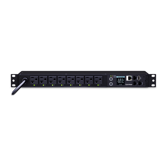
Product Features (1U 20A Models) Front Panel Description NEMA Type IEC Type A. AC Inlet/ AC Power Cord - Used to connect PDU to utility power or UPS. B. AC Output Receptacles - Provides power for connected equipment. C. Status Indicator - Indicates the condition of the PDU (eg. load or environment status). -
Page 8: Technical Specifications
Product Features (2U Models) Front Panel Description NEMA Type IEC Type A. AC Inlet/ AC Power Cord - Used to connect PDU to utility power or UPS. B. AC Output Receptacles - Provides power for connected equipment. C. Status Indicator - Indicates the condition of the PDU (eg. load or environment status). -
Page 9: Installation Guide
Installation Guide Please use only the provided screws through the entire installation process. Horizontal Installation For 1U Model Step 1. Mounting Bracket Installation Use the provided Mounting Bracket Screws (8) to attach the SHORT Mounting Brackets (2) to the PDU. If you plan on attaching the Cord Retention Tray to the PDU, you will need to use the LONG Mounting Brackets (2). -
Page 10: For 2U Model
Installation Guide Step 3. Cord Retention Tray Installation (optional) Attach the Cord Retention Tray to the PDU with the 4 supplied Cord Retention Tray Mounting Screws. Tighten the Cord Retention Tray with the screw on it. Use the provided Cable Ties to fasten each cord to the Cord Retention Tray. For 2U Model Step 1. - Page 11 Installation Guide Step 2. PDU Mounting Use the supplied Washers (4) and Screws (4) to secure the PDU to your existing rack system Step 3. Cord Retention Tray Installation (optional) Attach the Cord Retention Tray to the PDU with the 8 supplied Cord Retention Tray Mounting Screws.
-
Page 12: Vertical Installation
Installation Guide Vertical Installation For 1U Model Step 1. Mounting Bracket Installation Use the provided Mounting Bracket Screws (8) to attach the SHORT Mounting Brackets (2) to the PDU. Step 2. PDU Mounting Use the supplied Washers (2) and Screws (2) to secure the PDU to your existing rack system. -
Page 13: Output Power Cord
Installation Guide Step 2. Align and insert the Cable Tie from the bottom side of the Fixed Stand and fasten it as shown below. Output Power Cord Step 1. Align and insert the Cable Tie from the upper side of the Fixed Stand and fasten it as shown below. -
Page 14: Network Installation
PDU, and the other end to a network port. Step 2 – Establish the PDU IP address Assigning an IP address to the CyberPower PDU requires the user to have an available IP address that is valid on the respective network. If an available IP address is unknown, contact the network administrator to obtain one. -
Page 15: Operation
Telnet and SSH The CyberPower PDU provides Telnet and Secure Shell (SSH) as Remote Management methods. Telnet uses user name and password as basic security while SSH has a higher security level with encryption of the transmitted packets including user name, password, and data. -
Page 16: Led Indicators
Outlet The outlet is off. Environmental Monitoring (optional) CyberPower PDUs along with the environment sensor (ENVIROSENSOR) provide temperature and humidity monitoring in a server closet and/or datacenter remotely. To connect the PDU with ENVIROSENSOR, use the RJ45 Ethernet Cable. Plug one end into the Daisy Chain (In)/ENVIROSENSOR port on the PDU and the other end into the RJ45 port on the ENVIROSENSOR (as shown below). -
Page 17: Firmware Upgrade
Note that the XXX is not part of the file name but is where the version number in the filename is given. Use the following steps to upgrade the firmware. 1. Download the latest firmware from www.cyberpower.com 2. Extract the file to “C:\” 3. Open a command prompt window and navigate to “C:\”. -
Page 18: Troubleshooting
Troubleshooting Problem Possible Cause Solution Reset Breaker, check the plug to PDU outlets do not 1. Breaker tripped insure its connected correctly. provide power to 2. Power cord is not If the problem remains, contact connected equipment properly plugged in technical support. -
Page 19: Customer Service & Warranty
CyberPower will inspect and examine the Product. If the Product is defective in material or workmanship, CyberPower will repair or replace it at CyberPower's expense, or, if CyberPower is unable to or decides not to repair or replace the Product (if defective) within a reasonable time, CyberPower will refund to you the full purchase price you paid for the Product (purchase receipt showing price paid is required). -
Page 20: Appendix A-Hyper Terminal
1. Yes 2. No Appendix B-Power Device Network Utility Overview The CyberPower Power Device Network Utility is an easy-to-use interface which is used for establishing IP addresses on CyberPower PDU devices. Installation Step 1. Download the Power Device Network Utility software. - Page 21 Appendix B-Power Device Network Utility Step 3. Choose an installation directory. Select Next (Shown in Figure 2.). Figure 2. Step 4. Select Install to comfirm the settings and install (Shown in Figure 3.). Figure 3. Step 5. Select Finish to finalize the installation (Shown in Figure 4.). Figure 4.
-
Page 22: Launch Program
Getting Started The Power Device Network Utility scans the network for devices with MAC addresses that match CyberPower network hardware. Once found, the device(s) can then be figured with a specific IP address, subnet mask, and gateway address. This allows the device(s) to function properly on the network and interface with CyberPower Management Console. -
Page 23: Advanced Settings
Appendix B-Power Device Network Utility Step 2. Assign a valid IP Address to the PDU Option 1: Assisted Setup (recommended) With the appropriate device selected from the Equipment List, open the Network Settings menu (Shown in Figure 6.). [Tools=>Device Setup]. In the Device Network Setting Menu, enter a valid IP address, subnet mask, and gateway address to setup the PDU device. - Page 24 Cyber Power Systems, Inc. www.cyberpower.com K01-0000545-00...
Need help?
Do you have a question about the PDU81001 and is the answer not in the manual?
Questions and answers