
Subscribe to Our Youtube Channel
Related Manuals for CyberPower PDU31 Series


Summary of Contents for CyberPower PDU31 Series
- Page 1 USER’S MANUAL Intelligent PDU Web Interface PDU31xxx PDU41xxx PDU71xxx PDU81xxx Copyright © 2018 Cyber Power Systems, Inc. All rights reserved. K01-E000003-02...
-
Page 2: Table Of Contents
Table of Contents Table Of Contents 1. Introduction ....................... 1 1.1 Brief Introduction to the Web Interface.................. 1 1.2 How to Log in ..........................1 1.3 General Settings ..........................2 1.3.1 Date and Time Settings ....................2 1.3.2 Daylight Saving Time ....................... 4 1.3.3 Device Identification ...................... - Page 3 Table of Contents 5.6 Console Service .......................... 72 5.7 FTP Service ..........................74 6. PDU Information .................... 75 Appendix A: PDU Network Daisy Chain ............76 Appendix B: Firmware Upgrade ..............80 Intelligent PDU Web Interface...
-
Page 4: Introduction
1.2 How to Log in Open a Web browser. Enter the IP address of the CyberPower PDU in the Browser Address Bar, and then press ENTER. Note: To look up the IP address, please refer to the LCD screen of the PDU. -
Page 5: General Settings
1. Introduction 1.3 General Settings These are the basic settings for the PDU. 1.3.1 Date and Time Settings The date and time can be set manually or synchronized with a Network Time Protocol (NTP) server. All time-related configurations are based on this setting. See System Tab >... - Page 6 1. Introduction Item Definition Date Format The options for date format selection. *Primary NTP Server: Users enter the IP address/domain name of the NTP server and choose local time zone based on their location. *Secondary NTP Server: Users enter the IP address/domain name of the NTP server and choose Using NTP Server local time zone based on their location.
-
Page 7: Daylight Saving Time
1. Introduction 1.3.2 Daylight Saving Time System Tab > Users adjust the daylight saving time according to their location. See General > Daylight Saving Time. System Tab > General > Daylight Saving Time Item Definition DST Configuration Disable Disable the DST function. Traditional US DST Start from the second Sunday in March to the first Sunday Time... -
Page 8: Device Identification
1. Introduction 1.3.3 Device Identification Users assign the device’s name, location, and the person to contact about issues. See System Tab > General > Identification. System Tab > General > Identification Item Definition Select the role of the PDU (HOST or GUEST#) if PDUs are daisy HOST/GUEST# chained. -
Page 9: Device Reset/Reboot
1. Introduction 1.3.4 Device Reset/Reboot System Tab > Users can reboot the PDU or reset all the settings to defaults. See Reset/Reboot. System Tab > Reset/Reboot Item Definition Reboot Power Distribution Unit Restart the PDU without power cycling any outlet. Reset the PDU to its factory default setting and Reset Power Distribution Unit restart it. -
Page 10: Environmental Monitoring
1. Introduction 1.3.5 Environmental Monitoring PDU with CyberPower ENVIROSENSOR can provide remote monitoring of temperature and humidity in a server closet and/or datacenter. You can set temperature and humidity threshold for event action warning. See Envir Tab > Status Envir Tab >... - Page 11 1. Introduction Item Definition Click Reset to reset the highest and lowest value to zero. Contact Display the current status of each input dry contact relay. Envir Tab > Configuration Item Definition Information Name The name entered by user to identify the ENVIROSENSOR. Location The location of the ENVIROSENSOR, entered by the user.
- Page 12 1. Introduction Item Definition The point where the environmental state changes from abnormal to normal and users receive a clearing event notification. The function of Hysteresis is to avoid receiving multiple event notifications. *For high threshold, the point is the threshold minus the Hysteresis value;...
-
Page 13: Advanced Power Management
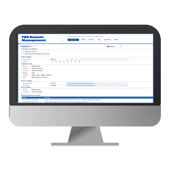
2. Advanced Power Management 2. Advanced Power Management 2.1 Remote Monitoring Users can see real-time readings of PDU vitals such as device load, power Summary consumption, and outlet status for an overview of current PDU status. See Tab, PDU Tab > Status, and PDU Tab >... - Page 14 2. Advanced Power Management Item Definition System Data The name of the PDU. For configuration, see System Tab > Name General > Identification. The location of the PDU. For configuration, see System Tab > Location General > Identification. The person accountable for the maintenance of the PDU. For Contact configuration, see System Tab >...
- Page 15 2. Advanced Power Management PDU Tab > Status > Device Item Definition Select the role of PDU (HOST or GUEST#) if PDUs are daisy HOST/GUEST# chained. Up to 3 GUEST PDUs can connect to 1 HOST PDU. Load Load current of the connected device(s), measured in Amps. Device Load Load power of the connected device(s), measured in Kilowatts and Kilovolt-Amps.
- Page 16 2. Advanced Power Management PDU Tab > Status > Outlet* *The above Outlet Status Page is available for Switched Metered by Outlet Series only. Item Definition Select the role of PDU (HOST or GUEST#) if PDUs are daisy HOST/GUEST# chained. Up to 3 GUEST PDUs can connect to 1 HOST PDU. Status The on/off status of each outlet.
-
Page 17: Visible Power Consumption
2. Advanced Power Management 2.2 Visible Power Consumption With comprehensive energy measurement data, users can gain more visibility to the total power usage of a PDU, as well as estimate the energy cost and CO2 emissions. The energy-trend report also helps users analyze their power utilization and to review Log Tab >... - Page 18 2. Advanced Power Management Log Tab > Graphing Item Definition Select the role of PDU (HOST or GUEST#) if PDUs are daisy HOST/GUEST# chained. Up to 3 GUEST PDUs can connect to 1 HOST PDU. The time period is used to create a retroactive graph of the Graph Period status records.
- Page 19 2. Advanced Power Management Log Tab > Energy Records Item Definition Select the role of PDU (HOST or GUEST#) if PDUs are daisy HOST/GUEST# chained. Up to 3 GUEST PDUs can connect to 1 HOST PDU. Energy consumed by connected device(s) during a specific Interval Energy (kWh) time interval, measured in kWh.
- Page 20 2. Advanced Power Management Log Tab > Maintenance Item Definition Event Logs Clear All Logs Clear the existing event logs. The number of the existing event logs and the maximum The Number of number of the event logs that can be recorded. Once the Events maximum number is reached, new events overwrite oldest events in memory.
- Page 21 2. Advanced Power Management Item Definition The time that records have been kept. A smaller recording interval leads to less remaining time while a larger Remaining Time recording interval leads to more remaining time. Once the maximum number is reached, new status records overwrite oldest status records in memory.
-
Page 22: Event Logging
2. Advanced Power Management 2.3 Event Logging Users can view all the events, including log in/out records and configuration changes. The timestamp is recorded in a 24-hour format. See Log Tab > Syslog Log Tab > Event Logs. For event logs, Users can clear the existing event logs in Log Tab >... - Page 23 2. Advanced Power Management Syslog Server Page Item Definition Server IP The IP address of Syslog server. Server Port The port number that Syslog server uses to communicate. Logs Tab > Event Logs Intelligent PDU Web Interface...
-
Page 24: Power Protection
2. Advanced Power Management 2.4 Power Protection The configurable load threshold can be set to prevent an overload condition. Coldstart and system configurations are also offered for different user needs. See PDU Tab > Device Manager. PDU Tab > Manager > Device Item Definition Select the role of PDU (HOST or GUEST#) if PDUs are daisy... - Page 25 2. Advanced Power Management Item Definition Set the value for the total current on the PDU that will Low Load Threshold signal a low load warning. Must be lower than Near Overload Threshold. When load current exceeds the corresponding threshold, no outlets will be allowed to turn on.
-
Page 26: Event Action Notification
2. Advanced Power Management 2.5 Event Action Notification Users decide the event actions for which they receive notifications. When a certain event happens, an automatic notification will be sent to users so that they can make timely decisions to prevent potential problems. See System Tab >... - Page 27 2. Advanced Power Management Event Action Page The Event Action Page enables users to modify the notification method. Item Definition Logs Event Record the device event in the Event Logs. Send an email to a specific user. Send E-mail An available SMTP server is necessary. Post Trap Send a SNMP trap to a specific IP address.
-
Page 28: Event Action Recipient Settings
2. Advanced Power Management 2.5.1 Event Action Recipient Settings The following provides e-mail receiver configurations. 2.5.1.1 E-mail Notification Set the proper SMTP server settings so that users can receive an email when a specific event occurs. See System Tab > Notification > SMTP Server. System Tab >... - Page 29 2. Advanced Power Management Item Definition Account Account used for Authentication. Password Password used for Authentication. Enable/Disable TLS or SSL to encrypt the SMTP Secure connection connection. The port number that the PDU uses to communicate with Service Port SMTP server. Users can set up to five e-mail recipients in designated email address format.
- Page 30 2. Advanced Power Management Configure E-mail Recipient Page Add New E-mail Recipient Page Intelligent PDU Web Interface...
-
Page 31: Snmp Trap Notification
2. Advanced Power Management 2.5.1.2 SNMP Trap Notification System Set up to 10 SNMP trap receivers to be notified when an event occurs. See > Notification > Trap Receivers. System > Notification > Trap Receivers Item Definition Configure Trap Receiver Click on the trap name to enter the Name Page. - Page 32 2. Advanced Power Management Configure Trap Receiver Page Add New Trap Receiver Page Intelligent PDU Web Interface...
- Page 33 2. Advanced Power Management Item Definition Name The name of trap receiver. IP Address The IP address of the trap receiver. If choosing the SNMPv1 option as the trap type for a trap SNMPv1 receiver, select the corresponding community. See System Tab >...
-
Page 34: Sms Notification
2. Advanced Power Management 2.5.1.3 SMS Notification Short Message Service (SMS) is used by mobile communication systems to send a short message to a specific mobile phone number. Standardized communication protocols allow the exchange of short text messages between mobile devices. The system provides four methods for users to choose how they want to send a message. - Page 35 2. Advanced Power Management System > Notification > SMS Service Using HTTP GET: Use the example where Clickatell is the SMS provider. The basic form of URL using the HTTP GET method is: http://api.clickatell.com/http/sendmsg?user=tedmosby&password=himym&api_id =2014331&to=E_PHONE_NUMBER&text=E_PHONE_MESSAGE Query String in the URL Definition Replace “tedmosby”...
- Page 36 2. Advanced Power Management System > Notification > SMS Service Using HTTP POST: Use the example where Clickatell is the SMS provider. The basic form of URL is: http://api.clickatell.com/http/sendmsg The basic form of body is: user=tedmosby&password=himym&api_id=2014331&to=E_PHONE_NUMBER&text =E_ MESSAGE Query String in Body Definition Replace “tedmosby”...
- Page 37 2. Advanced Power Management System > Notification > SMS Service Using Mail: Users set the SMTP server in System Tab > Notification > SMTP Server first, and then enter the following information. Item Definition Address Enter the e-mail of the recipient. The Subject field shown in the e-mail message, entered by Subject user.
- Page 38 2. Advanced Power Management Users can set up to 10 mobile phone numbers as SMS recipients who will receive a System Tab > short message notification when a specific event occurs. See Notification > SMS Recipients. System Tab > Notification > SMS Recipients Item Definition Configure SMS...
- Page 39 2. Advanced Power Management Configure SMS Receiver Page Add New SMS Receiver Page Intelligent PDU Web Interface...
-
Page 40: Outlet Management
3. Outlet Management 3. Outlet Management The following provides the outlet configurations to meet different application scenarios. 3.1 Remote Outlet On/Off/Reboot PDU Tab > Outlet Action > Users can turn on, turn off, or reboot individual outlet. See Control. (For Switched Metered by Outlet Series and Switched Series only.) PDU Tab >... - Page 41 3. Outlet Management Item Definition Selected outlets will be immediately turned off and then be Reboot turned on again according to each outlet’s Reboot Duration PDU Tab > Manager > Outlet. Selected outlets will be turned off according to each outlet's Power Off Delay.
-
Page 42: Scheduled Outlet On/Off/Reboot
3. Outlet Management 3.2 Scheduled Outlet On/Off/Reboot Outlet(s) can be set to automatically turn on, turn off, or reboot at scheduled times. PDU Tab > Outlet Action > Schedule. (For Switched Metered by Outlet Series and Switched Series only.) PDU Tab > Outlet Action > Schedule Select the role of PDU (HOST or GUEST#) first if PDUs are daisy chained. - Page 43 3. Outlet Management Add New Action Schedule Page Up to 10 scheduled settings are allowed. Item Definition Enable Check this box to activate the scheduled action function. The name entered by the user to identify the specific scheduled Name event. The action will be performed when the scheduled event takes place.
-
Page 44: Sequencing Power On/Off
3. Outlet Management 3.3 Sequencing Power On/Off Enable users to turn on, turn off, or reboot the outlets in sequence. When powering on the connected devices, the sequential power-on method is recommended to avoid high inrush current. See PDU Tab > Manager > Outlet. (For Switched Metered by Outlet Series and Switched Series only.) PDU Tab >... - Page 45 3. Outlet Management Outlet Configuration Page Item Definition The name entered by the user to identify the selected outlet or Name multiple outlet configuration. Action Configuration *Instant: Turn on/off the outlet immediately. Power On/Off *Delay: Delay time before turning on/off the outlet. Valid values Delay are within the range of 1 to 7,200 seconds.
- Page 46 3. Outlet Management Item Definition Peak Load Restore the peak load of each outlet to zero. Energy Restore the energy of each outlet to zero. Intelligent PDU Web Interface...
-
Page 47: Wake On Lan (Wol)
3. Outlet Management 3.4 Wake on LAN (WoL) When turning on an outlet, a Wake on LAN packet can be sent to the connected computer to awaken it. It is necessary for the computer to support this function and is configured as "Enabled"... - Page 48 3. Outlet Management PDU Tab > Wake on LAN > Lists Item Definition If the PowerPanel Client option in PDU Tab > Wake on LAN > WoL Client List Features is selected, the PowerPanel® List will be automatically added to the WoL Client list. Click New to enter the Add Wake on LAN Receiver Page.
- Page 49 3. Outlet Management Add Wake on LAN Receiver Window Item Definition Active Enable/Disable the Wake on LAN function. The IP address of the computer. This IP must be within the same IP Address subnet as the PDU. Up to 50 IP addresses are supported. Outlet Select the outlet that provides power to the computer.
-
Page 50: Graceful Computer Shutdown
3. Outlet Management 3.5 Graceful Computer Shutdown After the connected computer is installed with PowerPanel Business Edition Client or Center and establishes communication with the PDU, its IP address will be automatically displayed in the PowerPanel® List shown below. This computer can perform a safe shutdown before the outlet powering the computer turns off, thus avoiding data loss. -
Page 51: Cisco Energywise
3. Outlet Management 3.6 Cisco EnergyWise Users can manage and control all Cisco EnergyWise entities and configure settings. PDU Tab > EnergyWise > Configuration PDU Tab > EnergyWise > Children List. PDU Tab > EnergyWise > Configuration Item Definition Version The version of EnergyWise supported. - Page 52 3. Outlet Management PDU Tab > EnergyWise > Children List Click the Name field in parent and/or children list to enter the EnergyWise Parent Configuration Page EnergyWise Child Configuration Page. Intelligent PDU Web Interface...
- Page 53 3. Outlet Management EnergyWise Parent Configuration Page EnergyWise Child Configuration Page Item Definition The name entered by the user to identify an EnergyWise entity. Name The maximum length is 31 characters. This parameter is a string entered by the user to describe the Role function of the entity.
- Page 54 3. Outlet Management Item Definition This parameter, entered by the user, shows the value of an entity’s Importance importance and must be between 1 and 100. Intelligent PDU Web Interface...
-
Page 55: Security
4. Security 4. Security The following provides account configurations to protect against unauthorized entry. 4.1 Login Authentication There are five options for login authentication. Only one user can log in to the web interface at a time. System Tab > Security > Authentication Item Definition Login Authentication... - Page 56 4. Security Item Definition Log in with user name and password to authenticate with LDAP server first. If the LDAP server fails to respond, LDAP, Local then the user name and password configured in Local Configuration can be used. See System Tab >...
-
Page 57: Using Local Configuration For Authentication
4. Security 4.1.1 Using Local Configuration for Authentication System Tab > Security > Local Configuration There are two types of account: administrator and viewer. Click User Name or Password field to enter Administrator Page Viewer Page. Users can also click NEW to enter Add Outlet User Page to create an outlet account. - Page 58 4. Security Administrator Page Viewer Page Intelligent PDU Web Interface...
- Page 59 4. Security Item Definition The administrator can access all functions, including Administrator Enable/Disable the Viewer account. For login configuration, users can only create one administrator account. User Name Enter the new user name. Current Enter the current password for authentication. Password New Password Enter the new password.
- Page 60 4. Security Add Outlet User Page* *The above Add Outlet User Page is available for Switched Metered by Outlet Series and Switched Series only. Users can create an outlet account that is allowed to control assigned outlet(s). Item Definition Active Enable or disable the user account.
-
Page 61: Using Radius Configuration For Authentication
4. Security 4.1.2 Using RADIUS Configuration for Authentication System Tab > Security > RADIUS Configuration Click Add Server to enter Radius Server Configuration Page to create a server. Intelligent PDU Web Interface... - Page 62 4. Security Radius Server Configuration Page Item Definition Server IP The IP address of RADIUS server. Shared Secret The shared secret of RADIUS server. Server Port The UDP port used by the RADIUS server. Use user name and password to authenticate with RADIUS server, Test Setting and save information of RADIUS server if authentication succeeds.
-
Page 63: Using Ldap Configuration For Authentication
4. Security 4.1.3 Using LDAP Configuration for Authentication System Tab > Security > LDAP configuration Click Add Server to enter LDAP Server Configuration Page to create a server. Intelligent PDU Web Interface... - Page 64 4. Security LDAP Server Configuration Page Item Definition LDAP Server The IP address of LDAP server. LDAP SSL To communicate with LDAP server by LDAPS. Port The TCP port used by the LDAP(S) server. Base DN The base DN of LDAP server. Login Attribute The login attribute of LDAP user entry.
-
Page 65: Timeout Setting
4. Security 4.2 Timeout Setting System > Security > Session Control. Configure the idle login sessions. See System > Security > Session Control Item Definition Login Session The time in minutes that the system waits before automatically Timeout logging off. Intelligent PDU Web Interface... -
Page 66: Network Service
5. Network Service 5. Network Service The following provides the network configurations. 5.1 TCP/IPv4 Setting Display the current TCP/IPv4 settings and allow users to select the option to obtain TCP/IP settings by DHCP. See System > Network Service > TCP/IPv4. System >... -
Page 67: Tcp/Ipv6 Setting
5. Network Service 5.2 TCP/IPv6 Setting Display the current TCP/IPv6 settings and allow users to assign the IPv6 address either by router control or manually. See System > Network Service > TCP/IPv6. System > Network Service > TCP/IPv6 Item Definition IPv6 Interface Displays the current IPv6 address. -
Page 68: Snmpv1 Service Setting
5. Network Service 5.3 SNMPv1 Service Setting System Tab > Network Service > Allow users to perform SNMPv1 configurations. See SNMPv1 Service. System Tab > Network Service > SNMPv1 Service Item Definition SNMPv1 Service Allow Access Enable or disable the SNMPv1 service. Click the SNMP Trap Community field to enter the SNMPv1 Page. - Page 69 5. Network Service SNMPv1 Page Item Definition The name used to access the SNMP community from a Network Community Management System (NMS). Its maximum length is 15 characters. The IP address or IP address mask can be accessed by the NMS. A specific IP address allows access only by the NMS with the specified IP Address.
-
Page 70: Snmpv3 Service Setting
5. Network Service 5.4 SNMPv3 Service Setting Users can perform SNMPv3 configurations. Authentication type or privacy type are provided to strengthen security. See System Tab > Network Service > SNMPv3 Service. System Tab > Network Service > SNMPv3 Service Item Definition SNMPv3 Service Allow Access... - Page 71 5. Network Service SNMPv3 Page Item Definition Access Enable or disable the SNMPv3 service. The name that identifies the SNMPv3 user. It must be 1 to 31 User Name characters long. Authentication The password used to generate the key for authentication. It Password must be 16 to 31 characters long.
-
Page 72: Web Service
5. Network Service 5.5 Web Service Select the Enable HTTP/HTTPS option to access the HTTP/HTTPS Service and configure HTTP/HTTPS port settings. See System Tab > Network Service > Web Service. System Tab > Network Service > Web Service Item Definition Access Enable or disable HTTP/HTTPS service. - Page 73 5. Network Service Item Definition The TCP/IP port of the Hypertext Transfer Protocol (HTTP); 80 is the default value. HTTP Port Users can also change the port setting to any unused port from 5000 to 65535 to enhance security. Https Settings The TCP/IP port of the Hypertext Transfer Protocol Secure (HTTPS);...
- Page 74 5. Network Service Click the Valid Certificate link, and the Installed Certificate Page will appear. Installed Certificate Page Click the Upload Certificate link, and the Change Certificate Page will appear. Change Certificate Page Intelligent PDU Web Interface...
-
Page 75: Console Service
5. Network Service 5.6 Console Service Select the Enable options to allow access using Telnet/SSH service and configure Telnet/SSH port settings. See System Tab > Network Service > Console Service. System Tab > Network Service > Console Service Item Definition Access Enable access using Telnet or SSH version 2, which transmits Allow Access... - Page 76 5. Network Service Item Definition The TCP/IP port that SSH uses to communicate; 22 is the default value. SSH Port Users can change port setting to any unused port from 5000 to 65535 to enhance security. Display the status of hostkey fingerprint to show whether it is Hostkey Status valid or invalid.
-
Page 77: Ftp Service
5. Network Service 5.7 FTP Service Allow users to enable/disable the FTP server service and configure the TCP/IP port of the FTP server. The FTP server is used for upgrading Firmware. See System Tab > Network Service > FTP Service. System Tab >... -
Page 78: Pdu Information
6. PDU Information 6. PDU Information Display the system information of the PDU. See System > About. System > About Item Definition Information Model Name Model name of the PDU. Serial Number Serial Number of the PDU. Hardware Version The hardware version of the PDU. Firmware Version The current firmware version installed on the PDU. -
Page 79: Appendix A: Pdu Network Daisy Chain
APPENDIX Appendix A: PDU Network Daisy Chain The daisy-chain function allows up to four PDUs to be connected together to be monitored and controlled from one IP address. When PDUs are connected, two roles are defined: Host and Guest. Up to three Guest PDUs can be connected to one Host PDU. - Page 80 APPENDIX What remote management protocols are supported in PDU daisy-chains? Currently users can monitor and control daisy-chained PDUs through Web interface (HTTP/HTTPS) or SNMP protocols. What functions on the Web pages does daisy-chain support? Please find in below table: Summary Device Status Outlet Status Device Manager...
- Page 81 APPENDIX What will happen if an Ethernet cable is disconnected in the PDU daisy-chain? For example, if four PDUs are connected and the cable connecting Guest 1 and 2 is disconnected, then Guest 2 and 3 will no longer be detected by the Host PDU. An event showing that Guest 2 and 3 are removed will be recorded in the Host PDU.
- Page 82 APPENDIX Yes, once the Guest PDUs are removed, the Status Records logged in the Host PDU will be cleared. As long as the Host PDU does not connect to other PDUs, the Status Records of the disconnected PDU can be displayed when it is re-connected to the Host PDU. If the Host PDU connects to different PDUs, the Status Records of the removed PDU will be entirely cleared.
-
Page 83: Appendix B: Firmware Upgrade
- ftp> open 192.168.22.126 21 (for example: 192.168.22.126 is the current IP of the PDU and 21 is the default ftp port for the PDU) - Connected to 192.168.22.126. - 220 CyberPower FTP Server Ready. - User (192.168.22.126:(none)):cyber - 331 User name okay, need password. - Page 84 - ftp> open 192.168.22.126 21 (for example: 192.168.22.126 is the current IP of the PDU and 21 is the default ftp port for the PDU) - Connected to 192.168.22.126. - 220 CyberPower FTP Server Ready. - User (192.168.22.126:(none)):cyber - 331 User name okay, need password.
- Page 85 Use the following steps to upgrade the firmware. 1. Download the Upgrade and Configuration Utility from www.cyberpower.com 2. Open the Upgrade and Configuration Utility from Start > All Programs > CyberPower Upgrade and Configuration Utility. 3. Wait for search to finish (shown in Figure 1).
- Page 86 APPENDIX 4. Check the checkbox to select devices listed in the Operation View (Shown in Figure Figure 2 5. Make sure Account and Password are valid on selected devices (Shown in Figure 3). Figure 3. 6. Select Upgrade Firmware. Intelligent PDU Web Interface...
- Page 87 APPENDIX 7. Click Browse to locate and select the firmware and data file to be updated (Shown in Figure 4). Figure 4. 8. Click OK in the Upgrade Firmware confirmation window (Shown in Figure 5). Figure 5. Intelligent PDU Web Interface...
- Page 88 APPENDIX 9. The upgrade progress bar will show in Last Action column (Shown in Figure 6). Figure 6. 10. The result of firmware upgrade will show in Result column (Shown in Figure 7). Figure 7. Note: If you don’t want to wait for the firmware upgrade, you can stop the process by clicking Abort in the Action menu.
- Page 89 Use the following steps to upgrade the firmware. 1. Download the latest firmware from www.cyberpower.com 2. Extract the file to the root directory of a USB flash drive with FAT32 formatting. Please note that the two files below should be available in order to complete the firmware upgrade process: *cpsmpdumadata_xxx.bin...
- Page 90 Contact Information Feel free to contact our Tech Support department with installation, troubleshooting, or general product questions. Cyber Power Systems, Inc. Web: www.cyberpower.com For USA and Canada: 4241 12th Ave East, Suite 400 Shakopee, MN55379 Toll-free: (877) 297-6937 For all other regions: Please visit our website for local contact information.
Need help?
Do you have a question about the PDU31 Series and is the answer not in the manual?
Questions and answers