CyberPower PDU81001 User Manual
Switched metered by outlet/metered by outlet series/switched/monitored 1u/2u/0u series
Hide thumbs
Also See for PDU81001:
- User manual (24 pages) ,
- User manual (37 pages) ,
- User manual (37 pages)

Related Manuals for CyberPower PDU81001


Summary of Contents for CyberPower PDU81001
- Page 1 Power Distribution Unit USER'S MANUAL Copyright © 2018 Cyber Power Systems, Inc. All rights reserved. K01-0000545-02...
-
Page 2: Table Of Contents
Unattended/Automatic Shutdown .........23 Firmware Upgrade...........24 Troubleshooting ............28 Conformance Approvals .........28 Customer Service & Warranty .......29 Product Registration ............29 CyberPower International ..........29 Limited Warranty..............29 Appendix A-Hyper Terminal ........30 Appendix B-Power Device Network Utility ..30 Overview ...................30 Installation ................30 Launch Program ..............32 Getting Started ..............32... -
Page 3: Model List
Model List Switched Metered by Outlet Series PDU81001 PDU81003 PDU81101 PDU81002 PDU81007 PDU81102 PDU81004 PDU81008 PDU81104 PDU81005 PDU81009 PDU81 1 05 PDU81006 PDU81404 PDU81405 Metered by Outlet Series PDU71001 PDU71003 PDU71002 PDU71007 PDU71004 PDU71008 PDU71005 PDU71009 PDU71006 Switched Series PDU41001... -
Page 4: Introduction
Introduction Package Contents 1U Models Mounting Brackets: 2 short & 2 long 12 (Flat Head M4 x 8) 6 (M5 x 12) Rack Mounting Bracket Mounting Screws Screws/Washers Cord Retention Tray 6 (M3 x 6) Cord Retention Tray Mounting Screws Cable Ties: RJ45/DB9 Serial Port Qty: 12 (NEMA outlet PDU) -
Page 5: Models
Introduction Package Contents 2U Models Mounting Brackets x 2 12 (Flat Head M4 x 8) 6 (M5 x 12) Rack Mounting Bracket Mounting Screws Screws/Washers Cord Retention Tray x 2 12 (M3 x 6) Cord Retention Tray Mounting Screws Cable Ties: RJ45/DB9 Serial Port Qty: 24 (NEMA outlet PDU) Connection Cable... -
Page 6: 0U Models
(PDU81006/ PDU81104/ PDU41101/ PDU31002/ PDU71006/ PDU41006/ PDU31101) PDU41104/ PDU31006/ PDU31114) Before using, please check to ensure the package contains all the items shown above. If there are missing parts, please contact your local CyberPower technical support team for assistance. Check... -
Page 7: Product Features
L. Outlet Indicator (switched series only) – Indicates if the outlet is providing power to connected equipment. Rear Panel Description A. Ground Stud - Use to ground the PDU. Technical Specifications PDU81001 PDU81004 PDU71001 PDU71004 Model Name PDU41001... -
Page 8: 20A Models
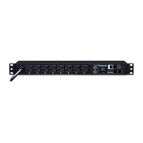
Product Features (1U 20A Models) Front Panel Description NEMA Type IEC Type A. AC Inlet/ AC Power Cord - Used to connect PDU to utility power or UPS. B. AC Output Receptacles - Provides power for connected equipment. C. Status Indicator - Indicates the condition of the PDU (eg. load or environment status). -
Page 9: Technical Specifications
Product Features (2U Models) Front Panel Description NEMA Type IEC Type A. AC Inlet/ AC Power Cord - Used to connect PDU to utility power or UPS. B. AC Output Receptacles - Provides power for connected equipment. C. Status Indicator - Indicates the condition of the PDU (eg. load or environment status). -
Page 10: 16/20A Models
Product Features (0U 16/20A Models) Front Panel Description NEMA Type IEC Type A. AC Inlet/ AC Power Cord - Used to connect PDU to utility power or UPS. B. Outlet Indicator (switched series only) – Indicates if the outlet is providing power to connected equipment. C. -
Page 11: Technical Specifications
Product Features (0U 16/20A Models) Rear Panel Description A. Bracket Screw Hole – Used to secure the Mounting Brackets or Mounting Pegs. Technical Specifications PDU81101 PDU31114 PDU81104 PDU81404 Model Name PDU41101 PDU41104 PDU41404 PDU31414 PDU31101 Input Nominal Voltage 100-120V 200-240V Frequency 50/60Hz 16A UL (Derated) -
Page 12: 30/32A Models
Product Features (0U 30/32A Models) Front Panel Description NEMA Type IEC Type A. AC Inlet/ AC Power Cord - Used to connect PDU to utility power or UPS. B. Outlet Indicator (switched series only) – Indicates if the outlet is providing power to connected equipment. C. -
Page 13: Technical Specifications
Product Features (0U 30/32A Models) Rear Panel Description A. Bracket Screw Hole – Used to secure the Mounting Brackets or Mounting Pegs. Technical Specifications PDU81105 PDU81405 PDU81102 PDU41105 PDU41405 Model Name PDU41102 PDU31102 PDU31106 PDU31406 Input Nominal Voltage 100-120V 200-240V Frequency 50/60Hz Maximum Input Current... -
Page 14: Installation Guide
Installation Guide Please use only the provided screws through the entire installation process. Horizontal Installation For 1U Models Step 1. Mounting Bracket Installation Use the provided Mounting Bracket Screws (8) to attach the SHORT Mounting Brackets (2) to the PDU. If you plan on attaching the Cord Retention Tray to the PDU, you will need to use the LONG Mounting Brackets (2). -
Page 15: For 2U Models
Installation Guide Step 3. Cord Retention Tray Installation (optional) Adjust the length of the Cord Retention Tray till the screw hole on the Tray and PDU are aligned. Attach the Cord Retention Tray to the PDU with the 4 supplied Cord Retention Tray Mounting Screws. - Page 16 Installation Guide Step 2. PDU Mounting Use the supplied Washers (4) and Screws (4) to secure the PDU to your existing rack system. Note: You may also use the screw sets provided by the rack to secure the PDU. Step 3. Cord Retention Tray Installation (optional) Adjust the length of the Cord Retention Tray till the screw hole on the Tray and PDU are aligned.
-
Page 17: Vertical Installation
Installation Guide Vertical Installation For 1U Models Step 1. Mounting Bracket Installation Use the provided Mounting Bracket Screws (8) to attach the SHORT Mounting Brackets (2) to the PDU. Step 2. PDU Mounting Use the supplied Washers (2) and Screws (2) to secure the PDU to your existing rack system. - Page 18 Installation Guide If there is no Keyhole Slot on your rack, please choose from the following methods that is best for your rack deployment to secure the PDU. Use the supplied Washers and Rack Mounting Screws to attach the Mounting Brackets to your existing rack system. Align the Keyhole Mounts to the Keyhole Slots on the Mounting Brackets.
- Page 19 Installation Guide Method 3...
- Page 20 Installation Guide Step 2. Cord Retention Tray Installation (optional) Adjust the length of the Cord Retention Tray till the screw hole on the Tray and PDU are aligned. Attach the Cord Retention Tray to the PDU with the supplied Cord Retention Tray Mounting Screws.
-
Page 21: Power Cord Direction Change - For 0U Pdu
Installation Guide Power Cord Direction Change – For 0U PDU Step 1. Remove the four screws from the power cord cover. Keep the screws for later use. Step 2. Rotate the power cord cover. Step 3. Install the power cord cover back to the PDU with the four screws. -
Page 22: Locking Power Cord - For Iec Type Pdu
Connection to any other type of wall receptacle may result in a shock hazard. Step 2. Plug the PDU into a CyberPower UPS system (recommended) or the wall receptacle. Step 3. Attach equipment It is extremely important not to exceed the PDUs maximum current load (as outlined in the Specifications section). -
Page 23: Network Installation
Step 2 – Establish the PDU IP address Assigning an IP address to the CyberPower PDU requires the user to have an available IP address that is valid on the respective network. If an available IP address is unknown, contact the network administrator to obtain one. -
Page 24: Operation
PDU Web Interface User’s Manual available for download from www.cyberpower.com. Telnet and SSH The CyberPower PDU provides Telnet and Secure Shell (SSH) as Remote Management methods. Telnet uses user name and password as basic security while SSH has a higher security level with encryption of the transmitted packets including user name, password, and data. -
Page 25: Led Indicators
Outlet The outlet is off. Environmental Monitoring (optional) CyberPower PDUs along with the environmental sensor (ENVIROSENSOR) provide temperature and humidity monitoring in a server closet and/or datacenter remotely. To connect the PDU with ENVIROSENSOR, use the RJ45 Ethernet Cable included with the ENVIROSENSOR. -
Page 26: Firmware Upgrade
Note that the XXX is not part of the file name but is where the version number in the filename is given. Prior to performing a firmware update, please: • Download the latest firmware from www.cyberpower.com. • Extract the downloaded firmware file to your local “C:\” drive. Note: 1. - Page 27 1. Download the Upgrade and Configuration Utility from www.cyberpower.com. 2. Open Upgrade and Configuration Utility from Start > All Programs > CyberPower Upgrade and Configuration Utility. 3. Wait for search to finish (Shown in Figure 1). Figure 1 4. Check the checkbox to select devices listed in the Operation View (Shown in Figure 2).
- Page 28 Firmware Upgrade 6. Select Upgrade Firmware. 7. Click Browse to locate and select the firmware and data file to be updated (Shown in Figure 4). Figure 4 8. Click OK in the Upgrade Firmware confirmation window (Shown in Figure 5). Figure 5 9.
- Page 29 Option 3: Use a USB Flash Drive Use the following steps to upgrade the firmware. 1. Download the latest firmware from www.cyberpower.com. 2. Extract the file to the root directory of a USB flash drive with FAT32 format. Please note that the two files below should be available in order to complete the firmware upgrade process: * cpsmpdumadata_xxx.bin...
-
Page 30: Troubleshooting
Troubleshooting Problem Possible Cause Solution Reset Breaker, check PDU outlets do 1. Breaker tripped the plug to insure its not provide power 2. Power cord is not connected correctly. If the to connected properly plugged problem remains, contact equipment technical support. Amperage The load indicator shows displayed on... -
Page 31: Customer Service & Warranty
Limited Warranty Read the following terms and conditions carefully before using the CyberPower PDU series. By using the Product, you consent to be bound by and become a party to the terms and conditions of this Limited Warranty. If you do not agree to the terms and conditions of this Warranty, you should return the Product for a full refund prior to using it. -
Page 32: Appendix A-Hyper Terminal
2. No Appendix B-Power Device Network Utility Overview The CyberPower Power Device Network Utility is an easy-to-use interface which is used for establishing IP addresses on CyberPower PDU devices. Installation Step 1. Download the Power Device Network Utility software from www.cyberpower.com. - Page 33 Appendix B-Power Device Network Utility Step 3. Choose an installation directory. Select Next (Shown in Figure 2). Figure 2 Step 4. Select Install to confirm the settings and install (Shown in Figure 3). Figure 3 Step 5. Select Finish to finalize the installation (Shown in Figure 4). Figure 4...
-
Page 34: Launch Program
IP address, subnet mask, and gateway address. This allows the device(s) to function properly on the network and interface with CyberPower Management Console. Step 1. Select the appropriate PDU device from the Equipment List (Shown in Figure 6). -
Page 35: Advanced Settings
Appendix B-Power Device Network Utility Step 2. Assign a valid IP Address to the PDU Option 1: Assisted Setup (recommended) With the appropriate device selected from the Equipment List, open the Network Settings menu (Shown in Figure 8) [Tools=>Device Setup]. In the Device Network Setting Menu, enter a valid IP address, subnet mask, and gateway address to setup the PDU device. -
Page 36: Appendix C-Pdu Daisy-Chain Function
New LCD PDU Daisy-Chain Function Introduction PDU81xxx/ 71xxx/ 41xxx/ 31xxx Appendix C-PDU Daisy-Chain Function The daisy-chain function allows up to four PDUs to be connected The daisy-chain function allows up to four PDUs to be connected together to be monitored and controlled from one IP address. together to be monitored and controlled from one IP address. - Page 37 Summary System Appendix C-PDU Daisy-Chain Function Device Status Status Records Identification Outlet Status Energy Records Device Manager Graphing Outlet Manager How to switch between Host and Guest PDUs on the Web Outlet Control interface? Outlet Schedule Functionality supported by daisy-chained PDUs will have the Host/ How to switch between Host and Guest PDUs on the Web interface? Guest # drop down menu displayed on the Web interface (as Functionality supported by daisy-chained PDUs will have the Host/ Guest #...
- Page 38 Appendix C-PDU Daisy-Chain Function Does the Host PDU record the Status Records of the Guest PDUs and itself? Yes, the Host PDU records the Status Records for all the PDUs in the daisy-chain. Will the Status Records of the Guest PDUs logged in the Host PDU be cleared if the Guest PDUs are disconnected from the Host PDU? Yes, once the Guest PDUs are removed, the Status Records logged...
- Page 39 Cyber Power Systems, Inc. www.cyberpower.com Copyright © 2018 Cyber Power Systems, Inc. All rights reserved. K01-0000545-02...
Need help?
Do you have a question about the PDU81001 and is the answer not in the manual?
Questions and answers