
Related Manuals for WAGO 750-872


Summary of Contents for WAGO 750-872
- Page 1 Modular I/O System Quick-Start Manual for ETHERNET Fieldbus Controller 750-872 Version 1.0.0...
- Page 2 • General Copyright 2008 by WAGO Kontakttechnik GmbH & Co. KG All rights reserved. WAGO Kontakttechnik GmbH &Co. KG Hansastraße 27 D-32423 Minden Phone: +49 (0) 571/8 87 – 0 Fax: +49 (0) 571/8 87 – 1 69 E-mail: info@wago.com Web: http://www.wago.com...
-
Page 3: Table Of Contents
Communication via the RJ-45 Interface [TCP/IP] ......20 2.4.2 Communication via the Serial Interface ..........24 Creating a Program................. 28 Downloading the Program to the 750-872 Controller......29 3 Simulation ....................30 Simulating Telecontrol via Ethernet (TCP/IP) with the WinPP104 Program ....................30 Simulating Telecontrol via the Serial Interface with the WinPP101 Program .................... -
Page 4: Important Notes
All other changes to the hardware and/or software and the non-conforming use of the components entail the exclusion of liability on the part of WAGO Kontakttechnik GmbH & Co. KG. -
Page 5: Symbols
References to additional literature, manuals, data sheets and INTERNET pages. 1.3 Number Notation Number code Example Note Decimal Normal notation Hexadecimal 0x64 C notation Binary '100' In inverted commas, '0110.0100' nibbles separated by dots (.) WAGO-I/O-SYSTEM 750 Telecontrol Quick-Start Manual... -
Page 6: Safety Information
Do not use contact sprays, which in extreme cases could impair the operation of the contact. The WAGO-I/O-SYSTEM 750 and its components are an open system. It must only be assembled in housings, cabinets or in electrical operation rooms. Access must only be given via a key or tool to authorized, qualified personnel. - Page 7 Important Notes • 7 Scope of Validity Additional Information: You will find the "Ethernet TCP/IP 750-872" and "WAGO-I/O-PRO CAA" manuals on the "WAGO-I/O-PRO CAA" CD (759-911), on the "ELECTRONICC Tools & Docs" CD (Item No.: 0888-0412/0001-0101) and www.wago.com on the Internet at:...
-
Page 8: Quick-Start Guide
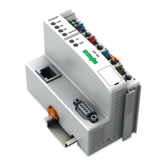
(see Fig. 1). For the application used in the example, it is sufficient to connect a jumper between "24V" and "+" and between "0V" and "-". Fig. 1: Connections for the 750-872 controller WAGO-I/O-SYSTEM 750 Telecontrol Quick-Start Manual... -
Page 9: Ethernet Network Start-Up
2.2 Ethernet Network Start-Up The IP address is conveniently assigned using the serial programming cable provided and the "WAGO Ethernet Settings" program. Connect your PC to the node's configuration and programming interface. Install the "WAGO Ethernet Settings" program. You will find it on the "Tools & Docs" CD as well as on the WAGO website under Service Downloads Software. -
Page 10: Fig. 3: Wago Ethernet Settings
10 • Quick-Start Guide Ethernet Network Start-Up Fig. 3: WAGO Ethernet Settings If the connection should time out, you can force the display to update with "Identify". If the problem should persist, check the COM port setting and the cabling. -
Page 11: Fig. 4: Setting The Pc Network Address Under Windows
Connections" "LAN Connection" "Properties". To do this, highlight the Internet protocol (TCP/IP) in the drop-down list box and press the "Properties" button. NOTE: The double assignment of IP addresses can lead to serious network errors. WAGO-I/O-SYSTEM 750 Telecontrol Quick-Start Manual... -
Page 12: Fig. 5: Ip Address Settings For The 750-872 Controller
Switch to the "TCP/IP" tab and enter an IP address for the node. Then transfer the change to the node with "Write". Fig. 5: IP address settings for the 750-872 controller Now connect the node to the Ethernet network. Either directly with a crossover cable to a PC or with a 1-to-1 patch cable to a hub or switch. -
Page 13: Fig. 6: Testing The Connection To The 750-872 Telecontrol Controller With "Ping
Quick-Start Guide • 13 Ethernet Network Start-Up Fig. 6: Testing the connection to the 750-872 telecontrol controller with "PING" If the node does not answer, please contact your network administrator. All settings can be viewed and changed using Web-Based Management http:// (WBM). -
Page 14: Installing The Wago Target System For Codesys
2.3 Installing the WAGO Target System for CoDeSys The following installation is only to be carried out when a CoDeSys version below 2.3.9.7 is used. From CoDeSys Version 2.3.9.7, the WAGO target system is already included in the installation. To install the WAGO target system, the installation file (Customer.exe) must first be downloaded and saved in any folder. -
Page 15: Fig. 10: Properties For The Copy Of Codesys V2.3
Quick-Start Guide • 15 Installing the WAGO Target System for CoDeSys Create a copy of the link to CoDeSys and open the "Properties" from the context menu (right mouse button). In the newly opened window you must enter a "space" and "–remote" in the "Target"... -
Page 16: Telecontrol With Codesys 2.3
You can start a new project with "File" "New". A brief example is shown below: Before programming the 750-872, the controller must be selected in the "Target system settings" dialog window. Fig. 11: Target system settings Please select "WAGO_750-872" as the target system. -
Page 17: Fig. 13: Wago-I/O-Pro Caa, I/O Configuration
In the example application, as described in section 2.1, only one digital input module 750-400, one digital output module 750-501 and one analog input module 750-461 have been plugged into the 750-872 controller. The 750-600 end module is plugged in at the extreme right. -
Page 18: Fig. 14: Wago-I/O-Pro Caa, I/O Configurator
In the example, the value "PLC" is to be used for the moment. The I/O configurator now shows the addresses of each channel on the module, that is to say each individual bit/word. Fig. 15: WAGO-I/O-PRO CAA, I/O configurator with 750-400, 750–501 and 750-461 WAGO-I/O-SYSTEM 750 Telecontrol Quick-Start Manual... -
Page 19: Fig. 16: Wago-I/O-Pro Caa, Variable Declaration In The I/O Configurator
If you click the address designation in front of the word "AT" with the left mouse button, a label will open in which a variable name can be entered (Fig. 13). Fig. 16: WAGO-I/O-PRO CAA, Variable declaration in the I/O configurator Now enter the following variable names: Start (for address %IX2.0) Valve1_closed (for address %IX2.1) -
Page 20: Communication Via The Rj-45 Interface [Tcp/Ip]
"<<DEL" button between the two windows. Settings can be adjusted by highlighting the interface in the bottom right-hand window. These are not relevant for this Quick-Start manual. WAGO-I/O-SYSTEM 750 Telecontrol Quick-Start Manual... -
Page 21: Fig. 19: Iec 60870 Settings - Config Ethernet
If a variable has not yet been created, a tick must be placed after the name of the variable against "Create variables automatically". As no further variables are WAGO-I/O-SYSTEM 750 Telecontrol Quick-Start Manual... -
Page 22: Fig. 21: Setting The Variables For Ethernet Messages
"Temperature", must be specified after the item NVA[INT]. An individual command "<45> Individual command" should also be included with the "SCD (BOOL)" variable "Valve2_open". Fig. 22: Settings - Ethernet commands WAGO-I/O-SYSTEM 750 Telecontrol Quick-Start Manual... -
Page 23: Fig. 23: Task Configuration
Now click on the newly created task with the right mouse button and select "Add program call". The appropriate program (PLC_PRG) can now be selected by clicking on the button with the three dots. Please continue with section 2.5 "Creating a program" for PLC_PRG. WAGO-I/O-SYSTEM 750 Telecontrol Quick-Start Manual... -
Page 24: Communication Via The Serial Interface
Fig. 24: IEC 60870 settings - Config with serial To remove an interface which appears in the right-hand window, the interface can be selected in this window and removed by clicking the "<<DEL" button between the two windows. WAGO-I/O-SYSTEM 750 Telecontrol Quick-Start Manual... -
Page 25: Fig. 25: Settings For The Serial Interface In Codesys
"SPI [BOOL]". Name the variable "Product_Request“. In this example no further variables are to be interrogated for this message, so the ticks must be removed after the following items: BL [BOOL], SB [BOOL], NT [BOOL] and IV [BOOL]. WAGO-I/O-SYSTEM 750 Telecontrol Quick-Start Manual... -
Page 26: Fig. 26: Message Settings - Serial
(PLC_PRG) is also called and processed for the newly generated module. The task configuration can be found on the "Resources" tab. The priority and the cyclic interval (call) for programs generated by the configuration generator ("IEC60870_ServerPRG_1_104 (PRG)" and "InitAction") can also be set here. WAGO-I/O-SYSTEM 750 Telecontrol Quick-Start Manual... -
Page 27: Fig. 27: Task Configuration Serial
The new task will be created. The program (PLC_PRG) can now be selected in the input box on the right with the help of the button with the three dots. WAGO-I/O-SYSTEM 750 Telecontrol Quick-Start Manual... -
Page 28: Creating A Program
Fig. 28: The program When the test program has been compiled without errors, it can now be loaded into the PLC. The compilation is started via "Project Translate all". The project can now be saved under "File" "Save" WAGO-I/O-SYSTEM 750 Telecontrol Quick-Start Manual... -
Page 29: Downloading The Program To The 750-872 Controller
Quick-Start Guide • 29 Downloading the Program to the 750-872 Controller 2.6 Downloading the Program to the 750-872 Controller Click "Online" "Communications parameters" in the menu and create a new communications channel. Select "TCP/IP" (3S TCP/IP driver). Enter the IP address of your coupler (e.g., 192.168.0.3) under “Address“. -
Page 30: Simulation
3.1 Simulating Telecontrol via Ethernet (TCP/IP) with the WinPP104 Program Start the WinPP104 program. Fig. 29: WinPP104 start screen The following settings must first be transferred under "Parameter setting" "General parameters" as can be seen in Fig. 29. WAGO-I/O-SYSTEM 750 Telecontrol Quick-Start Manual... -
Page 31: Fig. 30: General Settings Winpp 104
"Central processor" must be selected after the item "Function". The IP address will be added automatically. The IP address of the 750-872 controller (192.168.0.3) must be entered after the item "IP address of partner station". The other values can remain unchanged as can be seen in the illustration below. -
Page 32: Fig. 32: Parameterizing A Command Winpp104
The simulation can be started by clicking the button. All signals from the outstation (WAGO Controller 750-872) to the central processor (PC) are now displayed when their values change. Commands from the central processor to the station can be simulated. These can be executed under "Parameter setting"... -
Page 33: Simulating Telecontrol Via The Serial Interface With The Winpp101 Program
Simulating Telecontrol via the Serial Interface with the WinPP101 Program Fig. 33: Detail of system controller The command is sent to the station (Controller 750-872) by clicking Send and the digital output 2 is permanently energized. 3.2 Simulating Telecontrol via the Serial Interface with the WinPP101 Program Start the WinPP101 program. -
Page 34: Fig. 35: General Parameters Winpp101
Next the parameters for the function of the central processor must be entered. The window for setting the parameters is reached via "Parameter setting" "Receiver/Transmitter1…". The illustrations show the settings necessary for this example. Fig. 36: Receiver / Transmitter settings Page 1 WinPP101 WAGO-I/O-SYSTEM 750 Telecontrol Quick-Start Manual... -
Page 35: Fig. 37: Receiver / Transmitter Settings Page 2 Winpp101
The simulation can be started by clicking the button. All signals from the outstation (WAGO Controller 750-872) to the central processor (PC) are now displayed when their values change. Commands from the central processor to the station can be simulated. These can be executed under "Parameter setting"... -
Page 36: Fig. 38: Command Specification And Confirmation That The Command Has Arrived At The Controller
Simulating Telecontrol via the Serial Interface with the WinPP101 Program Fig. 38: Command specification and confirmation that the command has arrived at the controller !!! Important !!! All entries made in the parameter settings must be identical to the data in the CoDeSys program!!! WAGO-I/O-SYSTEM 750 Telecontrol Quick-Start Manual... -
Page 37: Appendix
Application Data Structure 4 Appendix 4.1 Application Data Structure Fig. 39: Application data structure ASDU: Telegram data unit Common ASDU address: The ASDU station address consists of an address part and one or more information objects WAGO-I/O-SYSTEM 750 Telecontrol Quick-Start Manual... -
Page 38: Difference Between Symmetrical And Asymmetrical Transmission Procedures
Difference between Symmetrical and Asymmetrical Transmission Procedures 4.2 Difference between Symmetrical and Asymmetrical Transmission Procedures Fig. 40: Symmetrical transmission procedures of the primary and secondary connection layer Fig. 41: Asymmetrical transmission procedure, primary and secondary station WAGO-I/O-SYSTEM 750 Telecontrol Quick-Start Manual... -
Page 39: Explanation Of The Set-Up Options For An Information Object
IV (BOOL) = A value is valid when it has been correctly measured. If the measuring function detects abnormal conditions at the information source (missing or non-functional measuring units), the value is identified as being invalid. The value of the information object is not defined under these WAGO-I/O-SYSTEM 750 Telecontrol Quick-Start Manual... -
Page 40: Finding Incorrect Address Information With Codesys
If the communication does not work, for example, no values will be displayed in the visualization. If only one information object is wrongly addressed or if it does not answer, this can be easily traced. WAGO-I/O-SYSTEM 750 Telecontrol Quick-Start Manual... - Page 41 Fig. 4: Setting the PC network address under Windows ........... 11 Fig. 5: IP address settings for the 750-872 controller ..........12 Fig. 6: Testing the connection to the 750-872 telecontrol controller with "PING" ..13 Fig. 7: Users and passwords of the 750-849 controller's web server......14 Fig.
- Page 42 If the communication does not work, for example, no values will be displayed in the visualization. If only one information object is wrongly addressed or if it does not answer, this can be easily traced. List of Figures ..........40 List of Figures ......................41 WAGO-I/O-SYSTEM 750 Telecontrol Quick-Start Manual...
- Page 44 WAGO Kontakttechnik GmbH &Co. KG PO Box 2880 • D-32385 Minden Hansastraße 27 • D-32423 Minden Phone: +49 (0) 571/8 87 – 0 Fax: +49 (0) 5 71/8 87 – 1 69 E-Mail: Internet: http://www.wago.com...
Need help?
Do you have a question about the 750-872 and is the answer not in the manual?
Questions and answers