
Subscribe to Our Youtube Channel
Related Manuals for WAGO 750-806


Summary of Contents for WAGO 750-806
- Page 1 WAGO-I/O-SYSTEM 750 Manual 750-806 Fieldbus Controller DeviceNet 16-bit CPU Version 2.0.0...
- Page 2 WAGO-I/O-SYSTEM 750 750-806 Fieldbus Controller DeviceNet © 2015 by WAGO Kontakttechnik GmbH & Co. KG All rights reserved. WAGO Kontakttechnik GmbH & Co. KG Hansastraße 27 D-32423 Minden Phone: +49 (0) 571/8 87 – 0 Fax: +49 (0) 571/8 87 – 1 69 E-Mail: info@wago.com...
-
Page 3: Table Of Contents
2.1.1 Subject to Changes ................12 2.1.2 Personnel Qualifications ..............12 2.1.3 Use of the WAGO-I/O-SYSTEM 750 in Compliance with Underlying Provisions ................... 12 2.1.4 Technical Condition of Specified Devices ......... 13 Safety Advice (Precautions) ..............14 System Description..................16 Manufacturing Number ................ - Page 4 Table of Contents WAGO-I/O-SYSTEM 750 750-806 Fieldbus Controller DeviceNet Display Elements ..................44 Operating Elements ................. 45 4.4.1 Service Interface ................. 45 4.4.2 Mode Selector Switch................. 46 4.4.3 DIP Switch..................48 4.4.3.1 Baud Rate Setting ................48 4.4.3.2 Station address ................49 Technical Data ..................
- Page 5 Setting the DeviceNet Station Address and Baud Rate ......83 Configuring Static and Dynamic Assemblies ......... 84 Programming the PFC Using WAGO-I/O-PRO ........95 Configuring the Fieldbus Controller using the I/O Configurator .... 98 Libraries for WAGO-I/O-PRO ............. 100 General Information about IEC Tasks ..........101 9.3.1...
- Page 6 Table of Contents WAGO-I/O-SYSTEM 750 750-806 Fieldbus Controller DeviceNet 11.1.3.1.2.2 Explicit Messages ............... 132 11.1.3.2 Data Exchange ................133 11.1.4 Process Data and Diagnostic Status ..........133 11.1.4.1 Process Image ................133 11.1.4.1.1 Assembly Instances ..............133 11.1.5 Configuration and Parameterization Using the Object Model ..135 11.1.5.1...
-
Page 7: Table Of Contents
WAGO-I/O-SYSTEM 750 Table of Contents 750-806 Fieldbus Controller DeviceNet 13.2.2 Special Conditions for Safe Use (ATEX Certificate TÜV 12 ATEX 106032 X) ..................203 13.2.3 Special Conditions for Safe Use (IEC-Ex Certificate TUN 09.0001 X)204 13.2.4 Special Conditions for Safe Use (IEC-Ex Certificate IECEx TUN 12.0039 X) .................. -
Page 8: Notes About This Documentation
Manual by third parties that violate pertinent copyright provisions is prohibited. Reproduction, translation, electronic and phototechnical filing/archiving (e.g., photocopying) as well as any amendments require the written consent of WAGO Kontakttechnik GmbH & Co. KG, Minden, Germany. Non-observance will involve the right to assert damage claims. Manual... -
Page 9: Symbols
WAGO-I/O-SYSTEM 750 Notes about this Documentation 750-806 Fieldbus Controller DeviceNet Symbols Personal Injury! Indicates a high-risk, imminently hazardous situation which, if not avoided, will result in death or serious injury. Personal Injury Caused by Electric Current! Indicates a high-risk, imminently hazardous situation which, if not avoided, will result in death or serious injury. - Page 10 Notes about this Documentation WAGO-I/O-SYSTEM 750 750-806 Fieldbus Controller DeviceNet Additional Information: Refers to additional information which is not an integral part of this documentation (e.g., the Internet). Manual Version 2.0.0...
-
Page 11: Number Notation
WAGO-I/O-SYSTEM 750 Notes about this Documentation 750-806 Fieldbus Controller DeviceNet Number Notation Table 1: Number Notation Number Code Example Note Decimal Normal notation Hexadecimal 0x64 C notation Binary '100' In quotation marks, nibble separated with '0110.0100' dots (.) Font Conventions... -
Page 12: Important Notes
2.1.1 Subject to Changes WAGO Kontakttechnik GmbH & Co. KG reserves the right to provide for any alterations or modifications that serve to increase the efficiency of technical progress. WAGO Kontakttechnik GmbH & Co. KG owns all rights arising from the granting of patents or from the legal protection of utility patents. -
Page 13: Technical Condition Of Specified Devices
Important Notes 750-806 Fieldbus Controller DeviceNet Appropriate housing (per 94/9/EG) is required when operating the WAGO-I/O- SYSTEM 750 in hazardous environments. Please note that a prototype test certificate must be obtained that confirms the correct installation of the system in a housing or switch cabinet. -
Page 14: Safety Advice (Precautions)
Install the device only in appropriate housings, cabinets or in electrical operation rooms! The WAGO-I/O-SYSTEM 750 and its components are an open system. As such, install the system and its components exclusively in appropriate housings, cabinets or in electrical operation rooms. Allow access to such equipment and fixtures to authorized, qualified staff only by means of specific keys or tools. - Page 15 WAGO-I/O-SYSTEM 750 Important Notes 750-806 Fieldbus Controller DeviceNet Do not use any contact spray! Do not use any contact spray. The spray may impair contact area functionality in connection with contamination. Do not reverse the polarity of connection lines! Avoid reverse polarity of data and power supply lines, as this may damage the devices involved.
-
Page 16: System Description
The fieldbus coupler/controller exchanges process data with the respective control via the respective fieldbus. The programmable fieldbus controllers (PFC) allow implementation of additional PLC functions. WAGO-I/O-PRO is used to program the fieldbus controllers according to IEC 61131-3. I/O modules for diverse digital and analog I/O signals as well as special functions can be connected to the fieldbus coupler/controller. -
Page 17: Manufacturing Number
WAGO-I/O-SYSTEM 750 System Description 750-806 Fieldbus Controller DeviceNet Manufacturing Number The serial number indicates the delivery status directly after production. This number is part of the labeling on the side of each component. In addition, the serial number is printed on the cover cap of the configuration and programming interface of the fieldbus coupler/controller, so that it can also be read when installed. -
Page 18: Component Update
System Description WAGO-I/O-SYSTEM 750 750-806 Fieldbus Controller DeviceNet Component Update For the case of an update of one component, the lateral marking on each component contains a prepared matrix. This matrix makes columns available for altogether three updates to the entry of the current update data, like production order number (NO;... -
Page 19: Assembly Guidelines/Standards
WAGO-I/O-SYSTEM 750 System Description 750-806 Fieldbus Controller DeviceNet Assembly Guidelines/Standards • DIN 60204 Electrical equipping of machines • DIN EN 50178 Equipping of high-voltage systems with electronic components (replacement for VDE 0160) • EN 60439 Low-voltage switchgear and controlgear assemblies Manual Version 2.0.0... -
Page 20: Power Supply
System Description WAGO-I/O-SYSTEM 750 750-806 Fieldbus Controller DeviceNet Power Supply 3.5.1 Isolation Within the fieldbus node, there are three electrically isolated potentials: • Electrically isolated fieldbus interface via transformer • Electronics of the fieldbus couplers/controllers and the I/O modules (internal bus) •... -
Page 21: System Supply
System Supply 3.5.2.1 Connection The WAGO-I/O-SYSTEM 750 requires a 24 V direct current system supply. The power supply is provided via the fieldbus coupler/controller and, if necessary, in addition via internal system supply modules 750-613. The power supply is reverse voltage protected. -
Page 22: Dimensioning
System Description WAGO-I/O-SYSTEM 750 750-806 Fieldbus Controller DeviceNet Figure 5: System Voltage for Standard Couplers/Controllers and Extended ECO Couplers Only reset the system simultaneously for all supply modules! Reset the system by simultaneously switching the system supply at all supply modules (fieldbus coupler/controller and potential supply module with bus power supply) off and on again. - Page 23 Consequently, an internal system supply module (750-613), e. g. in the middle of the node, should be added. Recommendation ® Utilize the smartDESIGNER feature WAGO ProServe software to configure fieldbus node assembly. You can test the configuration via the integrated plausibility check.
- Page 24 System Description WAGO-I/O-SYSTEM 750 750-806 Fieldbus Controller DeviceNet Fieldbus coupler or controller = Sum of all the internal current consumption of the connected (5 V) total I/O modules + internal current consumption of the fieldbus coupler/controller Internal system supply module...
-
Page 25: Field Supply
WAGO-I/O-SYSTEM 750 System Description 750-806 Fieldbus Controller DeviceNet 3.5.3 Field Supply 3.5.3.1 Connection Sensors and actuators can be directly connected to the relevant channel of the I/O module in 1, 2, 3 or 4 conductor connection technology. The I/O module supplies power to the sensors and actuators. -
Page 26: Table 5: Legend For Figure "Field Supply For Standard Couplers/Controllers And Extended Eco Couplers
System Description WAGO-I/O-SYSTEM 750 750-806 Fieldbus Controller DeviceNet Table 5: Legend for Figure “Field Supply for Standard Couplers/Controllers and Extended ECO Couplers” Field supply 24 V (-15 % / +20 %) Optional ground potential Power jumper contacts Potential distribution to adjacent I/O modules The field-side power supply is automatically derived from the power jumper contacts when snapping an I/O module. -
Page 27: Fusing
WAGO-I/O-SYSTEM 750 System Description 750-806 Fieldbus Controller DeviceNet 3.5.3.2 Fusing Internal fusing of the field supply is possible for various field voltages via an appropriate power supply module. Table 6: Power Supply Modules Order No. Field Voltage 750-601 24 V DC, Supply/Fuse... -
Page 28: Figure 8: Removing The Fuse Carrier
System Description WAGO-I/O-SYSTEM 750 750-806 Fieldbus Controller DeviceNet for example, to reach into one of the slits (one on both sides) and pull out the holder. Figure 8: Removing the Fuse Carrier Lifting the cover to the side opens the fuse carrier. -
Page 29: Figure 11: Fuse Modules For Automotive Fuses, Series 282
WAGO-I/O-SYSTEM 750 System Description 750-806 Fieldbus Controller DeviceNet Alternatively, fusing can be done externally. The fuse modules of the WAGO series 281 and 282 are suitable for this purpose. Figure 11: Fuse Modules for Automotive Fuses, Series 282 Figure 12: Fuse Modules for Automotive Fuses, Series 2006... -
Page 30: Supplementary Power Supply Regulations
750-806 Fieldbus Controller DeviceNet 3.5.4 Supplementary Power Supply Regulations The WAGO-I/O-SYSTEM 750 can also be used in shipbuilding or offshore and onshore areas of work (e. g. working platforms, loading plants). This is demonstrated by complying with the standards of influential classification companies such as Germanischer Lloyd and Lloyds Register. -
Page 31: Supply Example
WAGO-I/O-SYSTEM 750 System Description 750-806 Fieldbus Controller DeviceNet 3.5.5 Supply Example Suppl Sggggggggggggggggg The system supply and the field supply shall be separated! You should separate the system supply and the field supply in order to ensure bus operation in the event of a short-circuit on the actuator side. -
Page 32: Table 8: Legend For Figure "Supply Example For Fieldbus Coupler/Controller
System Description WAGO-I/O-SYSTEM 750 750-806 Fieldbus Controller DeviceNet Table 8: Legend for Figure “Supply Example for Fieldbus Coupler/Controller” Pos. Description Power Supply on coupler via external Supply Module Power Supply with optional ground Internal System Supply Module Separation module recommended... -
Page 33: Power Supply Unit
750-806 Fieldbus Controller DeviceNet 3.5.6 Power Supply Unit The WAGO-I/O-SYSTEM 750 requires a 24 VDC voltage (system supply). Recommendation A stable power supply cannot always be assumed everywhere. Therefore, you should use regulated power supplies to ensure the quality of the supply voltage (see also table “WAGO power supply units”). -
Page 34: Grounding
The separate grounding of the carrier rail can be easily set up with the aid of the WAGO ground wire terminals. Table 10: WAGO Ground Wire Terminals Order No. Description 283-609 1-conductor ground (earth) terminal block make an automatic contact to the carrier rail;... -
Page 35: Grounding Function
WAGO-I/O-SYSTEM 750 System Description 750-806 Fieldbus Controller DeviceNet 3.6.2 Grounding Function The grounding function increases the resistance against electro-magnetic interferences. Some components in the I/O system have a carrier rail contact that dissipates electro-magnetic interferences to the carrier rail. Figure 17: Carrier Rail Contact (Example) -
Page 36: Shielding
Higher shielding performance is achieved via low-impedance connection between shield and ground. For this purpose, connect the shield over a large surface area, e.g., WAGO shield connecting system. This is especially recommended for large- scale systems where equalizing current or high impulse-type currents caused by atmospheric discharge may occur. -
Page 37: Signal Lines
3.7.4 WAGO Shield Connecting System The WAGO shield connecting system consists of shield clamping saddles, busbars and various mounting carriers. These components can be used to achieve many different configurations. -
Page 38: Device Description
WAGO-I/O-PRO creates application programs that adhere to IEC 61131-3. CODESYS by 3S (the standard programming system) serves as the basis of WAGO-I/O-PRO, which was expanded specifically with the target files for all WAGO controllers. Compatibility with IEC-61131-3 programming software! - Page 39 WAGO-I/O-SYSTEM 750 Device Description 750-806 Fieldbus Controller DeviceNet The fieldbus controller supports the following DeviceNet functions: • Dynamic connection setup via the “Unconnected Message Manager Port” (UCMM) with up to 5 subscribers at the same time • Addressing the node via “Offline Connection Set” (e.g., in case of error) •...
-
Page 40: View
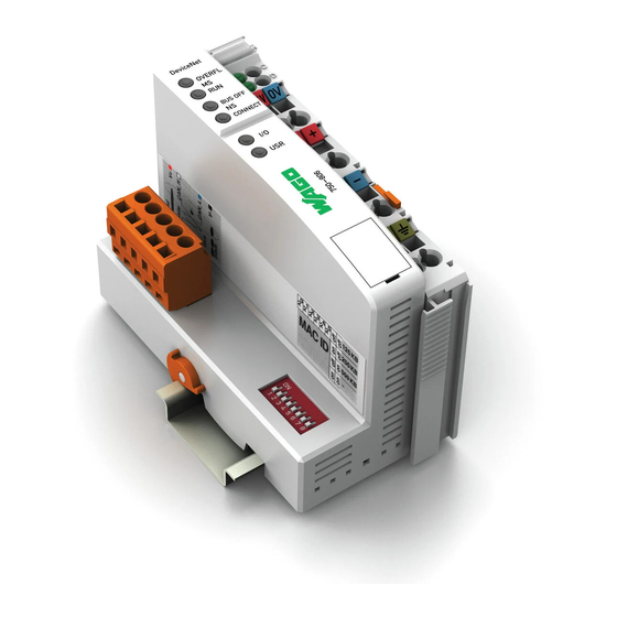
Device Description WAGO-I/O-SYSTEM 750 750-806 Fieldbus Controller DeviceNet View The view below shows the three parts of the device: • The fieldbus connection is on the left side. • LEDs for operation status, bus communication, error messages and diagnostics, as well as the service interface are in the middle area. -
Page 41: Table 11: Legend For Figure "View Devicenet Tm Fieldbus Controller
WAGO-I/O-SYSTEM 750 Device Description 750-806 Fieldbus Controller DeviceNet Table 11: Legend for Figure “View DeviceNet Fieldbus Controller” Desig- Pos. Meaning Details see Section nation OVERFL, RUN, “Device Description” > Status LEDs Fieldbus BUS OFF, “Display Elements” CONNECT Group marking carrier (retractable) with... -
Page 42: Connectors
Device Description WAGO-I/O-SYSTEM 750 750-806 Fieldbus Controller DeviceNet Connectors 4.2.1 Device Supply ® The device is powered via terminal blocks with CAGE CLAMP connections. The device supply generates the necessary voltage to power the electronics of the device and the internal electronics of the connected I/O modules. -
Page 43: Fieldbus Connection
WAGO-I/O-SYSTEM 750 Device Description 750-806 Fieldbus Controller DeviceNet 4.2.2 Fieldbus Connection The fieldbus connection for DeviceNet is made via Series 231 5-pin plug connector from the MULTI CONNECTION SYSTEM (MCS). A connector (OpenStyle) is the counterpart. The 231-305/010-000/050-000 connector is included. -
Page 44: Display Elements
Device Description WAGO-I/O-SYSTEM 750 750-806 Fieldbus Controller DeviceNet Display Elements The operating condition of the fieldbus controller or the node is displayed with the help of illuminated indicators in the form of light-emitting diodes (LEDs). The LED information is routed to the top of the case by light fibres. In some cases, these are multi-colored (red, green or red/green (=orange)). -
Page 45: Operating Elements
4.4.1 Service Interface The service interface is located behind the flap. It is used for the communication with WAGO-I/O-CHECK, WAGO-I/O-PRO and for update the firmware. Figure 25: Service Interface (Closed and Opened Flap) Table 16: Legend for Figure “Service Interface (Closed and Opened Flap)”... -
Page 46: Mode Selector Switch
You have the ability to program the behavior of the fieldbus controller so that the outputs switch in a safe condition in the case of program stop. For this WAGO-I/O-PRO allocates a function with GET_STOP_VALUE (library “System.lib”), which serves to recognize the last cycle before “STOP”. -
Page 47: Table 18: Mode Selector Switch Positions, Static Positions On Poweron/Reset
WAGO-I/O-SYSTEM 750 Device Description 750-806 Fieldbus Controller DeviceNet One of the following functions is active, depending on which of the three static positions — “top”, “center” or “bottom” — the switch is located at when energized or during a hardware or software reset:... -
Page 48: Dip Switch
Device Description WAGO-I/O-SYSTEM 750 750-806 Fieldbus Controller DeviceNet 4.4.3 DIP Switch Figure 27: DIP Switch The DIP switch is used to set the baud rate of the fieldbus controller and to set the DeviceNet station address (relating to DeviceNet , also called “MAC ID”). -
Page 49: Station Address
WAGO-I/O-SYSTEM 750 Device Description 750-806 Fieldbus Controller DeviceNet 4.4.3.2 Station address The station address is set using slide switches 1 to 6. The binary significance of the individual slide switches increases in the direction of the slide switch numbers. Slide switch 1 is used to set the lowest bit with a... -
Page 50: Technical Data
Device Description WAGO-I/O-SYSTEM 750 750-806 Fieldbus Controller DeviceNet Technical Data 4.5.1 Device Data Table 21: Technical Data, Device Data Width 51 mm Height (from upper edge of DIN 65 mm 35 rail) Depth 100 mm Weight approx. 195 g Protection type IP20 4.5.2... -
Page 51: Devicenet Tm Fieldbus
WAGO-I/O-SYSTEM 750 Device Description 750-806 Fieldbus Controller DeviceNet 4.5.3 DeviceNet Fieldbus Table 23: Technical Data, DeviceNet Fieldbus DeviceNet characteristics “Polled I/O Message Connection”, “Strobed I/O Message Connection”, “Change of State”/“Cyclic Message Connection”, UCMM using function blocks, DeviceNet master can be programmed 4.5.4... -
Page 52: Climatic Environmental Conditions
Device Description WAGO-I/O-SYSTEM 750 750-806 Fieldbus Controller DeviceNet Table 28: Technical Data – Data Contacts Data contacts Slide contact, hard gold plated, self- cleaning 4.5.7 Climatic Environmental Conditions Table 29: Technical Data – Climatic Environmental Conditions Operating temperature range 0 °C … 55 °C −20 °C …... -
Page 53: Approvals
Conformity Marking UL508 ODVA “Open DeviceNet Vendors Association” certified The following Ex approvals have been granted to 750-806 fieldbus coupler/controller: TÜV 07 ATEX 554086 X I M2 Ex d I Mb II 3 G Ex nA IIC T4 Gc II 3 D Ex tc IIIC T135°C Dc... - Page 54 Device Description WAGO-I/O-SYSTEM 750 750-806 Fieldbus Controller DeviceNet The following ship approvals have been granted to 750-806 fieldbus coupler/controller: ABS (American Bureau of Shipping) Federal Maritime and Hydrographic Agency BV (Bureau Veritas) DNV (Det Norske Veritas) Class B GL (Germanischer Lloyd) Cat.
-
Page 55: Standards And Guidelines
WAGO-I/O-SYSTEM 750 Device Description 750-806 Fieldbus Controller DeviceNet Standards and Guidelines 750-806 meets the following requirements on emission and immunity of interference: EMC CE-Immunity to interference acc. to EN 61000-6-2 EMC CE-Emission of interference acc. to EN 61000-6-3 EMC marine applications-Immunity to interference acc. -
Page 56: Mounting
Mounting WAGO-I/O-SYSTEM 750 750-806 Fieldbus Controller DeviceNet Mounting Installation Position Along with horizontal and vertical installation, all other installation positions are allowed. Use an end stop in the case of vertical mounting! In the case of vertical assembly, an end stop has to be mounted as an additional safeguard against slipping. - Page 57 WAGO-I/O-SYSTEM 750 Mounting 750-806 Fieldbus Controller DeviceNet Increase the total length using a coupler module for internal data bus extension! You can increase the total length of a fieldbus node by using a 750-628 I/O Module (coupler module for internal data bus extension). For such a configuration, attach a 750-627 I/O Module (end module for internal data bus extension) after the last I/O module of a module assembly.
-
Page 58: Mounting Onto Carrier Rail
WAGO Kontakttechnik GmbH & Co. KG supplies standardized carrier rails that are optimal for use with the I/O system. If other carrier rails are used, then a technical inspection and approval of the rail by WAGO Kontakttechnik GmbH & Co. KG should take place. -
Page 59: Wago Din Rail
WAGO-I/O-SYSTEM 750 Mounting 750-806 Fieldbus Controller DeviceNet 5.3.2 WAGO DIN Rail WAGO carrier rails meet the electrical and mechanical requirements shown in the table below. Table 31: WAGO DIN Rail Order number Description 210-113 /-112 35 x 7.5; 1 mm; steel yellow chromated; slotted/unslotted 210-114 /-197 35 x 15;... -
Page 60: Mounting Sequence
Don't forget the bus end module! Always plug a bus end module 750-600 onto the end of the fieldbus node! You must always use a bus end module at all fieldbus nodes with WAGO-I/O- SYSTEM 750 fieldbus couplers/controllers to guarantee proper data transfer. -
Page 61: Inserting And Removing Devices
WAGO-I/O-SYSTEM 750 Mounting 750-806 Fieldbus Controller DeviceNet Inserting and Removing Devices Perform work on devices only if they are de-energized! Working on energized devices can damage them. Therefore, turn off the power supply before working on the devices. Manual Version 2.0.0... -
Page 62: Inserting The Fieldbus Coupler/Controller
Mounting WAGO-I/O-SYSTEM 750 750-806 Fieldbus Controller DeviceNet 5.6.1 Inserting the Fieldbus Coupler/Controller When replacing the fieldbus coupler/controller for an already available fieldbus coupler/controller, position the new fieldbus coupler/controller so that the tongue and groove joints to the subsequent I/O module are engaged. -
Page 63: Inserting The I/O Module
WAGO-I/O-SYSTEM 750 Mounting 750-806 Fieldbus Controller DeviceNet 5.6.3 Inserting the I/O Module Position the I/O module so that the tongue and groove joints to the fieldbus coupler/controller or to the previous or possibly subsequent I/O module are engaged. Figure 32: Insert I/O Module (Example) Press the I/O module into the assembly until the I/O module snaps into the carrier rail. -
Page 64: Removing The I/O Module
Mounting WAGO-I/O-SYSTEM 750 750-806 Fieldbus Controller DeviceNet 5.6.4 Removing the I/O Module Remove the I/O module from the assembly by pulling the release tab. Figure 34: Removing the I/O Module (Example) Electrical connections for data or power jumper contacts are disconnected when removing the I/O module. -
Page 65: Connect Devices
WAGO-I/O-SYSTEM 750 Connect Devices 750-806 Fieldbus Controller DeviceNet Connect Devices Data Contacts/Internal Bus Communication between the fieldbus coupler/controller and the I/O modules as well as the system supply of the I/O modules is carried out via the internal bus. It is comprised of 6 data contacts, which are available as self-cleaning gold spring contacts. -
Page 66: Power Contacts/Field Supply
Connect Devices WAGO-I/O-SYSTEM 750 750-806 Fieldbus Controller DeviceNet Power Contacts/Field Supply Risk of injury due to sharp-edged blade contacts! The blade contacts are sharp-edged. Handle the I/O module carefully to prevent injury. Self-cleaning power jumper contacts used to supply the field side are located on the right side of most of the fieldbus couplers/controllers and on some of the I/O modules. -
Page 67: Connecting A Conductor To The Cage Clamp
Only one conductor may be connected to each CAGE CLAMP Do not connect more than one conductor at one single connection! If more than one conductor must be routed to one connection, these must be connected in an up-circuit wiring assembly, for example using WAGO feed- through terminals. Exception: If it is unavoidable to jointly connect 2 conductors, then you must use a ferrule to join the wires together. -
Page 68: Function Description
After error-free run-up, the PFC cycle starts with the mode selector switch at the top position, or on a Start command from WAGO-I/O-PRO. The input and output data for the fieldbus, I/O modules and the timer values are read. The PFC program contained in the RAM is then processed, after which the output data for the fieldbus and I/O modules is written to the process image. -
Page 69: Figure 38: Run-Up Of The Fieldbus Controller
WAGO-I/O-SYSTEM 750 Function Description 750-806 Fieldbus Controller DeviceNet Figure 38: Run-up of the Fieldbus Controller Manual Version 2.0.0... -
Page 70: Process Data Architecture
Function Description WAGO-I/O-SYSTEM 750 750-806 Fieldbus Controller DeviceNet Process Data Architecture 7.2.1 Basic Structure After switching on, the fieldbus controller identifies all I/O modules connected with the node that send or receive data (data width/bit width > 0). In a node can consist of a mixed arrangement of analog input/analog output modules and digital input/digital output modules and special modules. -
Page 71: Data Exchange
WAGO-I/O-SYSTEM 750 Function Description 750-806 Fieldbus Controller DeviceNet Data Exchange Objects are used for exchange of process data for the DeviceNet - fieldbus controller. For access from the network to the individual objects, connections between the required subscribes must first be established and connection objects set up or activated. -
Page 72: Communication Interfaces
256 ... 511), the PFC variables are mapped behind the physical process data. Access by the PLC to process data is made independently from the fieldbus system in all WAGO fieldbus controllers; access is always conducted through an application-related IEC-61131-3 program. -
Page 73: Figure 39: Memory Areas
WAGO-I/O-SYSTEM 750 Function Description 750-806 Fieldbus Controller DeviceNet Figure 39: Memory Areas In the memory space word 0 … 255, the fieldbus controller process image contains the physical data of the bus modules. The input module data can be read by the CPU and by the fieldbus side. -
Page 74: 750-806 Fieldbus Controller Devicenet Tm
(see section “Fieldbus Communication” > … > “Additional Assembly Instances 10 and 11”) or by using the dynamic assembly (see section “Programming PFC with WAGO-I/O-PRO” > “Special DeviceNet Characteristics of the Fieldbus Controller” > … > “Dynamic Assembly”). Other memory areas are also provided in the fieldbus controller, some of which cannot be accessed by the fieldbus side, however: •... -
Page 75: Figure 40: Example Declaration Of Remanent Flags By "Var Retain
Figure 40: Example Declaration of Remanent Flags by “var retain” This breakdown can be varied (see following explanation). NOVRAM memory allocation can be changed in WAGO-I/O-PRO! The breakdown of the NOVRAM can be modified when required in the programming software WAGO-I/O-PRO/Register “Resources”/Dialog window “Target system settings”. -
Page 76: Addressing
Function Description WAGO-I/O-SYSTEM 750 750-806 Fieldbus Controller DeviceNet 7.3.3 Addressing 7.3.3.1 Fieldbus-Specific Addressing After turning on the power supply, the assembly object combines data from the process image. As soon as a connection is established, a DeviceNet master (scanner) can address the data with “class”, “instance” and “attribute” and then access it or read and/or write via I/O connections. -
Page 77: Table 32: Input Process Image
WAGO-I/O-SYSTEM 750 Function Description 750-806 Fieldbus Controller DeviceNet Take into account the process data of previous I/O modules in case of an expansion! If a node is changed or expanded, this may result in a new process image structure. In this case, the process data addresses also change. In case of an expansion, the process data of all previous I/O modules has to be taken into account. -
Page 78: Absolute Addressing
Function Description WAGO-I/O-SYSTEM 750 750-806 Fieldbus Controller DeviceNet Output process image: Standard process data, output image (Assembly Class, Instance 1) Table 33: Output Process Image Bit 7 Bit 6 Bit 5 Bit 4 Bit 3 Bit 2 Bit 1 Bit 0... -
Page 79: Calculate Addresses
WAGO-I/O-SYSTEM 750 Function Description 750-806 Fieldbus Controller DeviceNet 7.3.3.3 Calculate Addresses The word address is the basses for calculating addresses. Bit address Word address .0 to .15 Byte address 1st byte: 2 x word address 2nd byte: 2 x word address + 1... -
Page 80: Example For Absolute Addresses
Function Description WAGO-I/O-SYSTEM 750 750-806 Fieldbus Controller DeviceNet 7.3.3.7 Example for Absolute Addresses Data width Inputs %IX14.0 ... 15 %IX15.0 ... 15 Byte %IB28 %IB29 %IB30 %IB31 Word %IW14 %IW15 DWord %ID7 Data width Outputs %QX5.0 ... 15 %QX6.0 ... 15... -
Page 81: Commissioning
WAGO-I/O-SYSTEM 750 Commissioning 750-806 Fieldbus Controller DeviceNet Commissioning This section shows a step-by-step procedure for starting up exemplarily a WAGO fieldbus node. Good example! This description is just an example and only serves to describe the procedure for a local start-up of a single DeviceNet fieldbus node with a non-networked computer under Windows. -
Page 82: Connecting Client Pc And Fieldbus Nodes
Commissioning WAGO-I/O-SYSTEM 750 750-806 Fieldbus Controller DeviceNet Connecting Client PC and Fieldbus Nodes 1. Mount the fieldbus node to the carrier rail. Observe the installation instructions described in “Mounting” section. 2. Use a fieldbus cable to connect the DeviceNet fieldbus node to the DeviceNet fieldbus card in your PC. -
Page 83: Setting The Devicenet ™ Station Address And Baud Rate
WAGO-I/O-SYSTEM 750 Commissioning 750-806 Fieldbus Controller DeviceNet ™ Setting the DeviceNet Station Address and Baud Rate ™ Set the required DeviceNet station address (“MAC ID”) using slide switches 1 … 6 of the DIP switch. Set the required baud rate using slide switches 7 and 8. -
Page 84: Configuring Static And Dynamic Assemblies
The sample node is configured with the following I/O modules: Launch the “RSNetWorx” configuration software. To load the EDS file “WAGO 750-806_2_8.eds”, click the “EDS Wizard” menu item in the “Tools” menu and follow the instructions. Additional Information The EDS file "WAGO 750-806_2_8.eds"... -
Page 85: Table 37: Data Configuration For Sample Nodes
Commissioning 750-806 Fieldbus Controller DeviceNet ™ Now select the DeviceNet Fieldbus Controller (750-806) in the tree structure under the “Communication Adapter” folder. Double-click to apply or drag & drop the selection to the right side of the screen. The fieldbus controller is added as a second icon on the right side of the screen. -
Page 86: Figure 43: Correlation Between Plc Variables And Pfc Variables
Commissioning WAGO-I/O-SYSTEM 750 750-806 Fieldbus Controller DeviceNet Figure 43: Correlation Between PLC Variables and PFC Variables ™ The DeviceNet Master (scanner) should have access to the physical inputs and to 4 bytes of PFC output variables in this example. For the static assembly for the TX configuration of the scanner, 4 bytes of PFC output variables are added to the quantity of input data. - Page 87 WAGO-I/O-SYSTEM 750 Commissioning 750-806 Fieldbus Controller DeviceNet Select the “Scan List” tab. ™ Click the [] button to move the DeviceNet Fieldbus Controller (750- 806) from the “Available Devices” window on the left side to the “Scan List” window. Click the “Edit I/O Parameters...” button.
-
Page 88: Figure 44: Mapping Of Inputs As Digital Inputs
Commissioning WAGO-I/O-SYSTEM 750 750-806 Fieldbus Controller DeviceNet Figure 44: Mapping of Inputs as Digital Inputs Table 38: Mapping of Inputs Bits Figure I:1.0 1 word reserved for scanner module I:1.1 1 word analog input channel 1 I:1.2 1 word analog input channel 2 I:1.3... -
Page 89: Figure 45: Mapping Outputs As Digital Outputs
With the dynamic assembly, data are mapped that should be transmitted via the fieldbus. The data are saved as classes, instances and attributes. Click the icon for the fieldbus controller 750-806 in the graphical representation so that the icon is highlighted. -
Page 90: Figure 47: Opening The "Class Instance Editor
Commissioning WAGO-I/O-SYSTEM 750 750-806 Fieldbus Controller DeviceNet Then click the Class Instance Editor... menu item in the “Device” menu. Figure 47: Opening the “Class Instance Editor” A window opens with the following warning: Figure 48: Warning Select a uniform number format! The editor changes parameters in the fieldbus controller. -
Page 91: Figure 49: Creating An Instance For Dynamic Assembly
WAGO-I/O-SYSTEM 750 Commissioning 750-806 Fieldbus Controller DeviceNet The [ENTER] closes the dialog window! Do not click [ENTER] because the dialog window closes and has to be opened again. Click the [Execute] button to create the instance for the dynamic assembly. -
Page 92: Figure 50: Entering Data To Send
Commissioning WAGO-I/O-SYSTEM 750 750-806 Fieldbus Controller DeviceNet 0x20 CC (Class) 0x24 II (Instance) 0x30 AA (Attribute) Figure 50: Entering Data to Send Click the [Execute] button to set the mapping. If the mapping was successful, the fieldbus node sends confirmation of execution. -
Page 93: Figure 51: Parameterization
WAGO-I/O-SYSTEM 750 Commissioning 750-806 Fieldbus Controller DeviceNet Figure 51: Parameterization Scroll down to the addresses ID#13 and #ID14. ID#13 is a pointer to the inputs (default = “4”). The parameter changes when inputs are mapped for the master. Because inputs can only be read and not written, this is not required. -
Page 94: 750-806 Fieldbus Controller Devicenet Tm
Commissioning WAGO-I/O-SYSTEM 750 750-806 Fieldbus Controller DeviceNet Then click the “Download parameters to the device” icon located at the far right of the dialog box. Click the [OK] button to confirm the setting. The dialog window closes. Then switch the fieldbus controller power supply of and on again. -
Page 95: Programming The Pfc Using Wago-I/O-Pro
If you have activated password protection for port 2455 on the “Security” page of the WBM, you have to log into WAGO-I/O-PRO in the menu Online > Log In to obtain programming access to the fieldbus controller (default password “wago”). -
Page 96: Figure 53: Logging Into The Plc Browser
To use the PLC browser functionality in WAGO-I/O-PRO, log into the PLC browser with the administrator user data (default user “admin”, password “wago”). Enter “login admin wago” in the command line of the PLC browser. Figure 53: Logging Into the PLC Browser A description of programming using WAGO-I/O-PRO is not included in this manual. -
Page 97: Figure 54: Dialog Window For Target System Settings
To ensure that you can access all I/O module data properly in your new project, first compile the I/O module configuration based on the existing fieldbus node hardware and map it in the configuration file “EA-config.xml”. As described below, this file can be generated via configuration using the WAGO I/O Configurator. Manual... -
Page 98: Configuring The Fieldbus Controller Using The I/O Configurator
The I/O Configurator is a plug-in integrated into WAGO-I/O-PRO used to determine addresses for I/O modules at a fieldbus controller. In the left half of the screen for the WAGO-I/O-PRO interface, select the tab Resources. To start the I/O Configurator, double-click in the tree structure on Control system configuration. - Page 99 (Menu project > transfer/transfer all) and download it in the fieldbus controller. Additional Information For a detailed description of using the software WAGO-I/O-PRO and the I/O Configurator, refer to the online Help function for WAGO-I/O-PRO. Manual...
-
Page 100: Libraries For Wago-I/O-Pro
WAGO-I/O-SYSTEM 750 750-806 Fieldbus Controller DeviceNet Libraries for WAGO-I/O-PRO Various libraries are available in WAGO-I/O-PRO for different IEC-61131-3 programming tasks. These contain function blocks for universal use that can streamline program creation. After incorporating the libraries, you can access their function blocks, functions and data types to use just like ones you have defined yourself. -
Page 101: General Information About Iec Tasks
Observe the watchdog sensitivity for cyclic tasks! The watchdog sensitivity indicates how many times the watchdog time is exceeded for an even to be triggered. You set the sensitivity in WAGO-I/O-PRO under Register Resources > Task Configuration for Cyclical Tasks. The values 1 and 0 are equivalent with regard to sensitivity. -
Page 102: Figure 55: Watchdog Runtime Is Less Than The Task Runtime
Programming the PFC Using WAGO-I/O-PRO WAGO-I/O-SYSTEM 750 750-806 Fieldbus Controller DeviceNet The following applies to cyclic tasks with watchdog activated: Reference for Watchdog Settings! For each tasks created, a watchdog can be enabled that monitors the execution time of a task. -
Page 103: Iec Task Sequence
WAGO-I/O-SYSTEM 750 Programming the PFC Using WAGO-I/O-PRO 750-806 Fieldbus Controller DeviceNet 9.3.1 IEC Task Sequence Determine the system time (tStart). If no full internal bus cycle has run since the last time the outputs were written: Wait until the next internal bus cycle is completed. -
Page 104: System Events
Possible events, for example: Stop, Start, Online change. A complete list of all system events is provided at WAGO-I/O-PRO in tab Resources > Task configuration > System events. Manual... -
Page 105: Enabling/Disabling System Events
Therefore use in system events exclusively Global variables and functions (Fun). Additional Information: Allocation of the system events to the specific modules to be called up is clarified in the manual for the programming tool WAGO-I/O-PRO in the Internet under http://www.wago.com. Manual... -
Page 106: Transfer The Iec Program To The Fieldbus Controller
WAGO I/O-PRO to set the values. Stop application before generating large boot projects! Stop the WAGO-I/O-PRO application via Online > Stop before generating a very large boot project, since this may otherwise cause stopping the internal bus. You can restart the application after creating the boot project. -
Page 107: Transfer Via Serial Service Port
If this is not the case, move the mode selector switch to the center or top position. Use the WAGO communication cable to connect a COM port of your PC to the fieldbus controller communication port. A communication driver is required for serial data transfer. This driver and its parameters must be entered in the WAGO-I/O-PRO in the dialog window “Communication parameters”. -
Page 108: Figure 58: Dialog Window "Communication Parameters
Programming the PFC Using WAGO-I/O-PRO WAGO-I/O-SYSTEM 750 750-806 Fieldbus Controller DeviceNet Figure 58: Dialog Window “Communication Parameters” In the selection window, mark the required driver in the right side of the window, Serial (RS-232) 3S Serial RS-232 driver, to configure the serial link between the PC and the fieldbus controller. -
Page 109: Figure 59: Logging In For Programming Access
If you have activated password protection for port 2455 on the “Security” page of the WBM, you have to log into WAGO-I/O-PRO in the menu Online > Log In to obtain programming access to the fieldbus controller (default password “wago”). -
Page 110: Transferring An Application Via Fieldbus
View WAGO-I/O-PRO as a subscriber in terms of UCMM! Transfer via the fieldbus is supported by UCMM. WAGO-I/O-PRO counts for downloading the PFC program as a subscriber. -
Page 111: Special Devicenet Characteristics Of The Fieldbus Controller
WAGO-I/O-SYSTEM 750 Programming the PFC Using WAGO-I/O-PRO 750-806 Fieldbus Controller DeviceNet You compiled project will also be executed by this method, if you restart the fieldbus controller or if there is a power failure. Once the program has been loaded, start program processing in the menu Online, menu item Start. -
Page 112: Change Mac Id By Sw
Programming the PFC Using WAGO-I/O-PRO WAGO-I/O-SYSTEM 750 750-806 Fieldbus Controller DeviceNet In addition to transmitting input/output data, the dynamic assembly can also be used for targeted selection of data that should be transmitted explicitly or not transmitted explicitly via the fieldbus. -
Page 113: Bit-Strobe
WAGO-I/O-SYSTEM 750 Programming the PFC Using WAGO-I/O-PRO 750-806 Fieldbus Controller DeviceNet 9.6.7 Bit-Strobe The “Bit-Strobe I/O Connection” is always a 1 to n multicast connection. In other words, a master can reach all slaves that support the Bit-Strobe command. Transmission is simultaneous. This allows for slave synchronization. -
Page 114: Diagnostics
Diagnostics WAGO-I/O-SYSTEM 750 750-806 Fieldbus Controller DeviceNet Diagnostics 10.1 LED Signaling For on-site diagnostics, the fieldbus controller has several LEDs that indicate the operational status of the fieldbus controller or the entire node (see following figure). Figure 60: Display Elements The diagnostics displays and their significance are explained in detail in the following section. -
Page 115: Evaluating The Fieldbus Status
WAGO-I/O-SYSTEM 750 Diagnostics 750-806 Fieldbus Controller DeviceNet 10.1.1 Evaluating the Fieldbus Status Communication via the fieldbus is by the top LED group. The two “MS” (“Module Status”) and “NS” (“Network Status”) LEDs are used for the status of the system and fieldbus connections. -
Page 116: Evaluating Node Status - I/O Led (Blink Code Table)
Diagnostics WAGO-I/O-SYSTEM 750 750-806 Fieldbus Controller DeviceNet 10.1.2 Evaluating Node Status – I/O LED (Blink Code Table) The communication status between fieldbus coupler/controller and the I/O modules is indicated by the I/O LED. Table 44: Node Status Diagnostics – Solution in Event of Error... -
Page 117: Figure 61: Node Status - I/O Led Signaling
WAGO-I/O-SYSTEM 750 Diagnostics 750-806 Fieldbus Controller DeviceNet Figure 61: Node Status – I/O LED Signaling Figure 62: Error Message Coding Example of a module error: • The I/O LED starts the error display with the first flashing sequence (approx. 10 Hz). -
Page 118: Table 45: Blink Code- Table For The I/O Led Signaling, Error Code 1
Diagnostics WAGO-I/O-SYSTEM 750 750-806 Fieldbus Controller DeviceNet • After the second break, the third flashing sequence starts (approx. 1 Hz): The I/O LED blinks twelve times. Error argument 12 means that the internal data bus is interrupted behind the twelfth I/O module. - Page 119 WAGO-I/O-SYSTEM 750 Diagnostics 750-806 Fieldbus Controller DeviceNet Table 45: Blink Code- Table for the I/O LED Signaling, Error Code 1 Error code 1: “Hardware and configuration error” Error Error Description Solution Argument The I/O module configuration after AUTORESET differs from the 1.
-
Page 120: Table 46: Blink Code Table For The I/O Led Signaling, Error Code 2
Diagnostics WAGO-I/O-SYSTEM 750 750-806 Fieldbus Controller DeviceNet Table 46: Blink Code Table for the I/O LED Signaling, Error Code 2 Error code 2: “Exceeded Process Image” Error Error Description Solution Argument Not used Process image is 1. Turn off the power supply of the node. -
Page 121: Table 48: Blink Code Table For The I/O Led Signaling, Error Code 4
WAGO-I/O-SYSTEM 750 Diagnostics 750-806 Fieldbus Controller DeviceNet Table 48: Blink Code Table for the I/O LED Signaling, Error Code 4 Error code 4: “Physical error, internal bus” Error Error Description Solution Argument 1. Turn off the power supply to the node. -
Page 122: Table 50: Blink Ccode Table For The I/O Led Signaling, Error Code 6
Diagnostics WAGO-I/O-SYSTEM 750 750-806 Fieldbus Controller DeviceNet Table 50: Blink Ccode Table for the I/O LED Signaling, Error Code 6 … 8 Error code 6 … 8: -not used- Error Error Description Solution Argument Not used Table 51: Blink Code Table for the I/O LED Signaling, Error Code 9 Error code 9: “CPU Trap error”... -
Page 123: Usr Led
WAGO-I/O-SYSTEM 750 Diagnostics 750-806 Fieldbus Controller DeviceNet Table 53: Blink Code Table for the I/O LED Signaling, Error Code 11 Error code 11: “Error in I/O modules with mailbox functionality” Error Error Description Remedy Argument Too many I/O modules with 1. -
Page 124: Evaluating Power Supply Status
Diagnostics WAGO-I/O-SYSTEM 750 750-806 Fieldbus Controller DeviceNet 10.1.3 Evaluating Power Supply Status The power supply unit of the device has two green LEDs that indicate the status of the power supplies. LED “A” indicates the 24 V supply of the coupler. -
Page 125: Fieldbus Communication
WAGO-I/O-SYSTEM 750 Fieldbus Communication 750-806 Fieldbus Controller DeviceNet Fieldbus Communication 11.1 DeviceNet DeviceNet is a network concept on the device level based on the serial bus system “Controller Area Network” (CAN). It is particularly characterized by easy addition and removal of devices during operation. The range of devices spans from simple light barriers to complex engine control units. -
Page 126: Network Structure
Fieldbus Communication WAGO-I/O-SYSTEM 750 750-806 Fieldbus Controller DeviceNet Additional Information The “Open DeviceNet Vendor Association” (ODVA) makes more information available on the Internet at: http://www.odva.org. Additional Information “CAN in Automation” (CiA) makes documentation about CAN networks available on the Internet at: http://www.can-cia.de. -
Page 127: Cabling
(worst case). 11.1.1.2 Cabling The connection of a WAGO fieldbus node to the DeviceNet bus cable is made by the included 5-pole plug, Series 231 (MCS). Figure 63: Plug Assignment for the Fieldbus Connection, Series 231 (MCS) -
Page 128: Topology
PE contact for the entire DeviceNet bus cable shield. Use the WAGO Shield Connecting System for optimal shielding! For the optimal connection between fieldbus cable shielding and functional ground, WAGO offers a cable shielding system (Series 790). -
Page 129: Figure 64: Devicenet Tm Network - Line Structure (Trunk Line) With Terminating Resistors
Network with Cable Branches To connect the nodes, a branching unit (“Multi-Port DeviceNet Tap”) has been developed by WAGO Kontakttechnik GmbH & Co. KG. The unit allows remote ® bus cables and drop lines to be connected using CAGE CLAMP technology. -
Page 130: Network Grounding
The programmable fieldbus controller 750-806 can assume the master operation when extended with the “DevNet.lib” library. The fieldbus devices are linked via interface modules. As an interface module, WAGO offers the PC interface cards for DeviceNet ISA DeviceNet Master 7 kByte (order No. 758-340), PC104 DeviceNet Master 7 kByte D-Sub, straight, angled (order No. -
Page 131: Network Communication
WAGO-I/O-SYSTEM 750 Fieldbus Communication 750-806 Fieldbus Controller DeviceNet 11.1.2 Network Communication 11.1.2.1 Objects, Classes, Instances and Attributes Protocol processing of DeviceNet is object oriented. Each node in the network is depicted as a collection of objects. Some related terms are defined below: •... -
Page 132: Characteristics Of Devicenet
Fieldbus Communication WAGO-I/O-SYSTEM 750 750-806 Fieldbus Controller DeviceNet 11.1.3 Characteristics of DeviceNet Devices DeviceNet - devices are defined by “Vendor ID” and “Device Type”: • Vendor ID 0x28 (40) • Device Type 0x0C (12), Communication Adapter 11.1.3.1 Communication Model 11.1.3.1.1 Message Groups... -
Page 133: Data Exchange
WAGO-I/O-SYSTEM 750 Fieldbus Communication 750-806 Fieldbus Controller DeviceNet 11.1.3.2 Data Exchange Process data are exchanged between scanner and DeviceNet device by means of the following three mechanisms: • Polled I/O Connection Slaves are polled cyclically by the master. • Change of Cyclic/State Message are transmitted either cyclically by the master or the slave or in the event of a state change. -
Page 134: 750-806 Fieldbus Controller Devicenet Tm
Fieldbus Communication WAGO-I/O-SYSTEM 750 750-806 Fieldbus Controller DeviceNet • Output 2 (“I/O Assembly Instance 2”) The digital output data image is transmitted from the master to the controller via the corresponding I/O message connection. The data length corresponds to the quantity of digital output data and is rounded up to full bytes. -
Page 135: Configuration And Parameterization Using The Object Model
Structure, content and coding of the EDS files are standardized, allowing configuration via configuration devices from various manufacturers. EDS file for fieldbus controller 750-806 750-806_1.EDS* “_1” indicates that this EDS file is valid for fieldbus controllers with firmware major version 1. -
Page 136: Table 57: Object Model Data Types
160 / instance 1 and 2 (USINT) = Class 166 / instance 1 (UINT) or class 166 / instance 1 and 2 (UINT) = Class 170 / instance 1 (UDINT). The DeviceNet fieldbus controller (750-806) is referred to as “Device” in the tables below. Manual... -
Page 137: 11.1.5.2.1 Object Classes
WAGO-I/O-SYSTEM 750 Fieldbus Communication 750-806 Fieldbus Controller DeviceNet 11.1.5.2.1 Object Classes Defined object classes: Table 58: Object Classes Object Class Instance Description Identity 0x01 “Device type”, “Vendor ID”, serial number, etc. Message Router 0x02 Routes explicit messages DeviceNet 0x03 Maintains the physical link to the DeviceNet network. -
Page 138: Identity Class (0X01)
Fieldbus Communication WAGO-I/O-SYSTEM 750 750-806 Fieldbus Controller DeviceNet 11.1.5.2.1.1 Identity Class (0x01) Instance 0 Table 59: Instance 0 Attributes Utilization Access Name Data Type Value Description in Device Rights required Revision UINT 0x01 Revision number of the class definition for the “Identity Object”... -
Page 139: Devicenet Object (0X03)
WAGO-I/O-SYSTEM 750 Fieldbus Communication 750-806 Fieldbus Controller DeviceNet 11.1.5.2.1.3 DeviceNet Object (0x03) Instance 0 Table 62: Instance 0 Attributes Utilization Access Name Data Value Description in Device Rights Type required Revision UINT 0x02 Revision number of the class definition for the “Identity Object”... -
Page 140: Assembly Object (0X04)
Fieldbus Communication WAGO-I/O-SYSTEM 750 750-806 Fieldbus Controller DeviceNet 11.1.5.2.1.4 Assembly Object (0x04) Instance 0 Table 65: Instance 0 Attributes Utilization Access Name Data Value Description in Device Rights Type required Revision UINT 0x02 Revision number of the class definition for the “Assembly Object”... -
Page 141: Table 68: Instance 2
WAGO-I/O-SYSTEM 750 Fieldbus Communication 750-806 Fieldbus Controller DeviceNet Instance 2 Table 68: Instance 2 Attributes Utilization Access Name Data Type Description in Device Rights Depending get/set Process Array of Process image, collection of all digital on the type image byte... -
Page 142: Table 73: Instance 7
Fieldbus Communication WAGO-I/O-SYSTEM 750 750-806 Fieldbus Controller DeviceNet Instance 7 Table 73: Instance 7 Attributes Utilization Access Name Data Type Description in Device Rights Depending Process Array of Process image, collection of all on the type image byte I/O module input data... -
Page 143: Table 78: Instance 12
WAGO-I/O-SYSTEM 750 Fieldbus Communication 750-806 Fieldbus Controller DeviceNet (For PFC with software version SW 01.06 or lower): PFC Output (I/O Assembly Instance 10): Only the PFC output variables are transmitted via the corresponding input/output communication link. The file length corresponds to the value in Class 100 / Instance 1 / Attribute 101 (BK_FBOUT_ VAR_CNT). -
Page 144: Table 79: Instance 13
Fieldbus Communication WAGO-I/O-SYSTEM 750 750-806 Fieldbus Controller DeviceNet Instance 13 Table 79: Instance 13 Attributes Utilization Access Name Data Type Description in Device Rights Depending Process Array of Process image, collection of all on the type image + byte Input data from I/O modules plus... -
Page 145: 11.1.5.2.1.4.1 Dynamic Assembly
WAGO-I/O-SYSTEM 750 Fieldbus Communication 750-806 Fieldbus Controller DeviceNet 11.1.5.2.1.4.1 Dynamic Assembly Two dynamic assembly instances are possible (Instance 100 and 101). Table 82: Dynamic Assembly Attributes Utilization Access Name Data Type Value Description in Device Rights required Number of UINT Mex. -
Page 146: Connection Object (0X05)
Fieldbus Communication WAGO-I/O-SYSTEM 750 750-806 Fieldbus Controller DeviceNet Instance Services Table 84: Instance Service Service Service Name Description Code 0x0Eh Get_Attribute_Single Used to read an object attribute value 0x10h Set_Attribute_Single Modifies an attribute value 0x09h Delete Deletes an assembly object 11.1.5.2.1.5 Connection Object (0x05) -
Page 147: Table 87: Instance 1
WAGO-I/O-SYSTEM 750 Fieldbus Communication 750-806 Fieldbus Controller DeviceNet Instance 1 (Explicit Messaging) Table 87: Instance 1 Attributes Utilization Access Name Data Type Description in Device Rights Available state USINT Status of the object required instance_ type USINT Displays I/O or messaging... -
Page 148: Table 88: Instance 2
Fieldbus Communication WAGO-I/O-SYSTEM 750 750-806 Fieldbus Controller DeviceNet Instance 2 (Poll I/O Connection) Table 88: Instance 2 Attributes Utilization Access Name Data Type Description in Device Rights Available state USINT Status of the object required instance_ USINT Displays I/O or messaging... -
Page 149: Table 89: Instance 3
WAGO-I/O-SYSTEM 750 Fieldbus Communication 750-806 Fieldbus Controller DeviceNet Instance 3 (Bit-Strobe I/O Connection) Table 89: Instance 3 Attributes Utilization Access Name Data Type Description in Device Rights Available state USINT Object state required instance_ USINT Displays I/O or messaging type... - Page 150 Fieldbus Communication WAGO-I/O-SYSTEM 750 750-806 Fieldbus Controller DeviceNet Table 89: Instance 3 Attributes Utilization Access Name Data Type Description in Device Rights required production_ USINT Defines the minimum time inhibi between data transmission t_time Instance 4 (Change of State und Cyclic I/O Connection)
-
Page 151: Figure 66: I/O Connection Object State
WAGO-I/O-SYSTEM 750 Fieldbus Communication 750-806 Fieldbus Controller DeviceNet Table 90: Instance 4 Attributes Utilization Access Name Data Type Description in Device Rights required consumed_ UINT Number of bytes in “consumed_connection_path” nnection_ attribute path_ length required consumed_ Array of Specifies application objects,... -
Page 152: Acknowledge Handler Object (0X2B)
Fieldbus Communication WAGO-I/O-SYSTEM 750 750-806 Fieldbus Controller DeviceNet 11.1.5.2.1.6 Acknowledge Handler Object (0x2B) Instance 0 Table 92: Instance 3 Attributes Utilization Access Name Data Type Value Description in Device Rights required Revision UINT 0x01 Revision number of the class definition for the “Acknowledge Handler... -
Page 153: Coupler Configuration Object (0X64)
WAGO-I/O-SYSTEM 750 Fieldbus Communication 750-806 Fieldbus Controller DeviceNet 11.1.5.2.1.7 Coupler Configuration Object (0x64) Instance 0 Table 95: Instance 0 Attributes Utilization Access Name Data Type Value Description in Device* Rights required Revision UINT 0x01 Revision number of the class definition for the “Identity Object”... -
Page 154: Table 96: Instance 1
Fieldbus Communication WAGO-I/O-SYSTEM 750 750-806 Fieldbus Controller DeviceNet Table 96: Instance 1 Attributes Utilization Access Name Data Type Description in Device Rights specific CnfLen. UINT Number of input/output bits for AnalogInp the analog input data words specific CnfLen. UINT Number of input/output bits for... - Page 155 WAGO-I/O-SYSTEM 750 Fieldbus Communication 750-806 Fieldbus Controller DeviceNet Table 96: Instance 1 Attributes Utilization Access Name Data Type Description in Device Rights specific get/set BK_SEL_STO UINT Power-up value for the receive RED_POLL_C path. “Polled I/O” enumeration _PATH for the assembly path, class and instance for the I/O module objects.
- Page 156 Fieldbus Communication WAGO-I/O-SYSTEM 750 750-806 Fieldbus Controller DeviceNet Table 96: Instance 1 Attributes Utilization Access Name Data Type Description in Device Rights specific get/set BK_BOI USIN Defines the default value for BIO (Obj. 0x03 Inst.1, Att.3.) It handles the CAN-...
- Page 157 WAGO-I/O-SYSTEM 750 Fieldbus Communication 750-806 Fieldbus Controller DeviceNet Table 96: Instance 1 Attributes Utilization Access Name Data Type Description in Device Rights specific get/set BK_static_anal UINT Defines how the values for the og_digital_inp analog and digital outputs bits ut_mapping determined.
- Page 158 Fieldbus Communication WAGO-I/O-SYSTEM 750 750-806 Fieldbus Controller DeviceNet Table 96: Instance 1 Attributes Utilization Access Name Data Type Description in Device Rights specific get/set BK_FBC_CFG UINT Contains configuration settings Bit 0: =1 turns off displaying current diagnostic messages via MS LED. The diagnostic messages, however, are still transmitted via the fieldbus.
-
Page 159: Discrete Input Point Object (0X65)
WAGO-I/O-SYSTEM 750 Fieldbus Communication 750-806 Fieldbus Controller DeviceNet Poll Connection: • 12-byte input process image (produced) • 10-byte output process image (consumed) BK_FBINP_VAR_CNT = 4; BK_FBOUT_VAR_CNT = 3 Poll Connection: • 15 bytes (produced) (12-byte input process image + 3-byte PFC output variables) •... -
Page 160: Discrete Output Point Object (0X66)
Fieldbus Communication WAGO-I/O-SYSTEM 750 750-806 Fieldbus Controller DeviceNet Instance 1 … 255 Table 100: Instance 1 Attributes Utilization Access Name Data Value Description in Device Rights Type Depending DIPOBJ_ 0: off Digital input bit on the type VALUE 1: on... -
Page 161: Analog Input Point Object (0X67)
WAGO-I/O-SYSTEM 750 Fieldbus Communication 750-806 Fieldbus Controller DeviceNet Instance 1 … 255 Table 104: Instance 1 Attributes Utilization Access Name Data Type Value Description in Device Rights Depending DIPOBJ_ 0: off Digital output bit on the type VALUE 1: on... -
Page 162: Analog Output Point Object (0X68)
Fieldbus Communication WAGO-I/O-SYSTEM 750 750-806 Fieldbus Controller DeviceNet Instance 1 … 255 Table 108: Instance 1 Attributes Utilization Access Name Data Type Value Description in Device Rights Depending AIPOBJ_ Array of Current Input data on the type VALUE Byte Input... -
Page 163: Module Configuration Object (0X80)
WAGO-I/O-SYSTEM 750 Fieldbus Communication 750-806 Fieldbus Controller DeviceNet Instance 1 … 255 Table 112: Instance 1 Attributes Utilization Access Name Data Type Value Description in Device Rights Depending AOPOBJ_ Array of Current Output data on the type VALUE Byte Output values... -
Page 164: Input Fieldbus Variable (0Xa0)
Fieldbus Communication WAGO-I/O-SYSTEM 750 750-806 Fieldbus Controller DeviceNet Instance 1 … 65 Attributes Utilization Access Name Data Description in Device Rights Type Depending AOPOBJ_ Array of Description of the connected on the type VALUE Byte I/O module (Instance 1 = Fieldbus... -
Page 165: Input Fieldbus Variable (0Xa1)
WAGO-I/O-SYSTEM 750 Fieldbus Communication 750-806 Fieldbus Controller DeviceNet Services Table 119: Service Service Service Name Description Code 0x0Eh Get_Attribute_Single Used to read an object attribute value 0x10h Set_Attribute_Single Used to write an object attribute value 11.1.5.2.1.14 Input Fieldbus Variable (0xA1) Class 161 PFC input variable bytes 256 …... -
Page 166: Output Fieldbus Variable (0Xa8)
Fieldbus Communication WAGO-I/O-SYSTEM 750 750-806 Fieldbus Controller DeviceNet 11.1.5.2.1.18 Output Fieldbus Variable (0xA8) Class 168 PFC output variable byte 1 … 255 Max. instance: 255 UINT 11.1.5.2.1.19 Output Fieldbus Variable (0xA9) Class 169 PFC output variable byte 256 Max. instance: 1 UINT 11.1.5.2.1.20 Input Fieldbus Variable (0xAA) -
Page 167: Output Fieldbus Variable (0Xad)
WAGO-I/O-SYSTEM 750 Fieldbus Communication 750-806 Fieldbus Controller DeviceNet 11.1.5.2.1.23 Output Fieldbus Variable (0xAD) Class 173 PFC output variable byte 1 … 128 Max. instance: 128 UDINT Starts with 2 bytes offset because the ranges overlap: Class 168 / Instance 2 and 3 (UINT) = Class 173 / Instance 1 (UDINT), etc. -
Page 168: I/O Modules
For detailed information on the I/O modules and the module variations, refer to the manuals for the I/O modules. You will find these manuals on the WAGO web pages under www.wago.com. More Information about the WAGO-I/O-SYSTEM Current information on the modular WAGO-I/O-SYSTEM is available in the Internet under: www.wago.com. -
Page 169: Process Data Architecture For Devicenet
WAGO-I/O-SYSTEM 750 I/O Modules 750-806 Fieldbus Controller DeviceNet 12.2 Process Data Architecture for DeviceNet For some I/O modules (and their variants), the architecture of the process data depends on the fieldbus. With the DeviceNet fieldbus controller, the process image uses a byte structure (no word alignment). -
Page 170: Digital Output Modules
I/O Modules WAGO-I/O-SYSTEM 750 750-806 Fieldbus Controller DeviceNet Example: 8-channel digital input modules with diagnostics (8 instances) Table 121: 8-Channel Digital Input Modules (8 Instances) Input Process Image Bit 7 Bit 6 Bit 5 Bit 4 Bit 3 Bit 2... -
Page 171: Analog Input Modules
WAGO-I/O-SYSTEM 750 I/O Modules 750-806 Fieldbus Controller DeviceNet 12.2.3 Analog Input Modules The analog input modules provide 16-bit measured data and 8 control/status bits per channel. DeviceNet does not use the 8 control/status bits, however, i.e., it does not access or evaluate them. -
Page 172: Analog Output Modules
I/O Modules WAGO-I/O-SYSTEM 750 750-806 Fieldbus Controller DeviceNet 12.2.4 Analog Output Modules The analog output modules provide 16-bit output values and 8 control/status bits per channel. DeviceNet does not use the 8 control/status bits, however, i.e., it does not access or evaluate them. -
Page 173: Specialty Modules
WAGO-I/O-SYSTEM 750 I/O Modules 750-806 Fieldbus Controller DeviceNet 12.2.5 Specialty Modules In addition to the data bytes, the control/status byte is also displayed for select I/O modules. This byte is used for the bi-directional data exchange of the I/O module with the higher-level control system. -
Page 174: Table 127: Output Process Image Counter Modules
I/O Modules WAGO-I/O-SYSTEM 750 750-806 Fieldbus Controller DeviceNet Table 127: Output Process Image Counter Modules Output process image Instance Byte designation Remark Control byte not used Counter setting value These specialty modules represent 1 x 6 bytes and occupy 1 instance in class (0x68). -
Page 175: Table 130: Input/Output Process Image, Pulse Width Output Modules
WAGO-I/O-SYSTEM 750 I/O Modules 750-806 Fieldbus Controller DeviceNet 2-channel pulse width output module, 24 VDC 750-511 (and all versions) In the input and output process image, pulse width output modules occupy 6 bytes of user data: 4 data bytes and two additional control/status bytes. 6 bytes are occupied in the process image. -
Page 176: Table 132: Output Process Image Counter Modules
I/O Modules WAGO-I/O-SYSTEM 750 750-806 Fieldbus Controller DeviceNet Table 132: Output Process Image Counter Modules Output process image Instance Byte designation Remark Control byte of counter 1 Counter setting value counter 1 Control byte of counter 2 Counter setting value counter 2 These specialty modules represent 2 x 3 bytes and occupy 2 instances in class (0x68). -
Page 177: Table 135: Input Process Image, Distance And Angle Measurement
WAGO-I/O-SYSTEM 750 I/O Modules 750-806 Fieldbus Controller DeviceNet Incremental encoder interface 750-631 The I/O module 750-631 occupies 5 bytes in the input process image and 3 bytes in the output process image. 6 bytes are occupied in the process image. -
Page 178: Table 138: Output Process Image, Proportional Valve Module
I/O Modules WAGO-I/O-SYSTEM 750 750-806 Fieldbus Controller DeviceNet Table 138: Output Process Image, Proportional Valve Module Output process image Instance Byte designation Remark Control byte MBX_CTRL Mailbox control byte MBX_DATA Mailbox data V1_CONTROL Valve 1 control V1_SETPOINTVALUE_L Valve 1, target value, low byte... -
Page 179: Table 141: Input Process Image, Incremental Encoder Interface Module
WAGO-I/O-SYSTEM 750 I/O Modules 750-806 Fieldbus Controller DeviceNet In Class 0x4, Instance 0x7 of the assembly object, the analog and digital input data occupy 6 or 12 bytes. The output data occupy 6 or 12 bytes in Class 0x4, Instance ID 0x1. -
Page 180: Table 143: Input/Output Process Image, Digital Impulse Interface
I/O Modules WAGO-I/O-SYSTEM 750 750-806 Fieldbus Controller DeviceNet Table 143: Input/Output Process Image, Digital Impulse Interface Input and Output Process Image Instance Byte designation Remark C0/S0 Control/status byte Data bytes These specialty modules represent 1 x 4 bytes and occupy 1 instance in class (0x67) and 1 instance in class (0x68). -
Page 181: Table 146: Input/Output Process Image, Incremental Encoder Interface Module
WAGO-I/O-SYSTEM 750 I/O Modules 750-806 Fieldbus Controller DeviceNet Incremental encoder interface 750-637 The incremental encoder interface module appears with 6 bytes of reference data in the input and output area of the process image, 4 data bytes and two additional control/status bytes. -
Page 182: Table 148: Input Process Image, Dali/Dsi Master Module
I/O Modules WAGO-I/O-SYSTEM 750 750-806 Fieldbus Controller DeviceNet DALI/DSI master module 750-641 In the input and output process image, the DALI/DSI master module occupies 6 data bytes, 5 data bytes and 1 additional control/status byte. 6 bytes are occupied in the process image. -
Page 183: Table 151: Output Process Image, Radio Receiver I/O Module
WAGO-I/O-SYSTEM 750 I/O Modules 750-806 Fieldbus Controller DeviceNet Table 151: Output Process Image, Radio Receiver I/O Module Output process image Instance Byte designation Remark Control byte not used These specialty modules represent 2 x 2 bytes and occupy 2 instances in class (0x67) and 2 instances in class (0x68). -
Page 184: Table 153: Output Process Image, Bluetooth ® Rf Transceiver
I/O Modules WAGO-I/O-SYSTEM 750 750-806 Fieldbus Controller DeviceNet Process data attach to this directly when the mailbox is hidden. When the mailbox is visible, the first 6, 12 or 18 bytes of process data are overlaid by the mailbox data, depending on their size. Bytes in the area behind the optionally visible ®... - Page 185 WAGO-I/O-SYSTEM 750 I/O Modules 750-806 Fieldbus Controller DeviceNet DALI Multi-Master module 753-647 The DALI Multi-Master module occupies a total of 24 bytes in the input and output process image. The DALI Multi-Master module can be operated in “Easy” mode (default) and “Full”...
- Page 186 I/O Modules WAGO-I/O-SYSTEM 750 750-806 Fieldbus Controller DeviceNet Table 155: Overview of Input Process Image in the “Easy” Mode Input Process Image Instance Byte designation Remark Not used DA = DALI address GA = Group address Table 156: Overview of the Output Process Image in the “Easy” mode...
-
Page 187: Table 155: Input/Output Process Image Of The Serial Interfaces
® The process image of the LON FTT module consists of a control/status byte and 23 bytes of bidirectional communication data that is processed by the WAGO- I/O-PRO function block “LON_01.lib”. This function block is required for the ® function of the LON FTT module and makes a user interface available on the control side. -
Page 188: Table 156: Input/Output Process Image Of The Serial Interfaces With Standard Data Format
I/O Modules WAGO-I/O-SYSTEM 750 750-806 Fieldbus Controller DeviceNet Table 156: Input/Output Process Image of the Serial Interfaces with Standard Data Format Input/Output Process Image Instance Byte designation Remark Control/status byte Data bytes These specialty modules represent 1 x 6 bytes and occupy 1 instance in class (0x67) and 1 instance in class (0x68). -
Page 189: Table 159: Input/Output Process Image, Data Exchange Modules
(Mode 1). While in operating mode with a suppressible mailbox (Mode 2), the mailbox and the cyclical process data are mapped next. The remaining bytes contain the remaining process data. Table 160: Input/Output Process Image, WAGO AS-Interface Master Module Input/Output Process Image Instance... -
Page 190: Table 161: Input/Output Process Image, I/O-Link Master
I/O Modules WAGO-I/O-SYSTEM 750 750-806 Fieldbus Controller DeviceNet Table 160: Input/Output Process Image, WAGO AS-Interface Master Module Input/Output Process Image Instance Byte designation Remark process data (0 ... 32 bytes) … These specialty modules represent 1 x 12...48 bytes and occupy 1 instance in class (0x67) and 1 instance in class (0x68). -
Page 191: Table 162: Can Gateway Input/Output Process Image
WAGO-I/O-SYSTEM 750 I/O Modules 750-806 Fieldbus Controller DeviceNet CAN gateway 750-658 The length of the process image of the CAN Gateway module can adjusted to a fixed size of 8, 12, 16, 20, 24, 32, 40 or 48 bytes. “Sniffer” and “Transparent” Operating Modes... -
Page 192: Table 164: Input/Output Process Image, Stepper Module
I/O Modules WAGO-I/O-SYSTEM 750 750-806 Fieldbus Controller DeviceNet Stepper module 750-670 750-671 750-672 750-673 The stepper module makes a 12-byte input/output process image available. The data to be sent and received is stored in up to 7 input/output bytes depending on the operating mode. -
Page 193: System Modules
WAGO-I/O-SYSTEM 750 I/O Modules 750-806 Fieldbus Controller DeviceNet 12.2.6 System Modules System Modules with Diagnostics 750-610, -611 Power supply modules (750-610 and -611) with diagnostics provide 2 bits in the input process image to monitor the power supply. Table 165: Input Process Image, System Modules with Diagnostics... -
Page 194: Use In Hazardous Environments
WAGO-I/O-SYSTEM 750 750-806 Fieldbus Controller DeviceNet Use in Hazardous Environments The WAGO-I/O-SYSTEM 750 (electrical equipment) is designed for use in Zone 2 hazardous areas. The following sections include both the general identification of components (devices) and the installation regulations to be observed. The individual subsections of the “Installation Regulations”... -
Page 195: Marking Configuration Examples
WAGO-I/O-SYSTEM 750 Use in Hazardous Environments 750-806 Fieldbus Controller DeviceNet 13.1 Marking Configuration Examples 13.1.1 Marking for Europe According to ATEX and IEC-Ex Figure 67: Side Marking Example for Approved I/O Modules According to ATEX and IECEx Figure 68: Text Detail – Marking Example for Approved I/O Modules According to ATEX and IECEx. -
Page 196: Table 167: Description Of Marking Example For Approved I/O Modules According To Atex And Iecex
Use in Hazardous Environments WAGO-I/O-SYSTEM 750 750-806 Fieldbus Controller DeviceNet Table 167: Description of Marking Example for Approved I/O Modules According to ATEX and IECEx Printing on Text Description TÜV 07 ATEX 554086 X Approving authority and certificate numbers IECEx TUN 09.0001 X... -
Page 197: Figure 69: Side Marking Example For Approved Ex I I/O Modules According To Atex And Iecex
WAGO-I/O-SYSTEM 750 Use in Hazardous Environments 750-806 Fieldbus Controller DeviceNet Figure 69: Side Marking Example for Approved Ex i I/O Modules According to ATEX and IECEx. Figure 70: Text Detail – Marking Example for Approved Ex i I/O Modules According to ATEX and IECEx. -
Page 198: Table 168: Description Of Marking Example For Approved Ex I I/O Modules According To Atex And Iecex
Use in Hazardous Environments WAGO-I/O-SYSTEM 750 750-806 Fieldbus Controller DeviceNet Table 168: Description of Marking Example for Approved Ex i I/O Modules According to ATEX and IECEx Inscription Text Description TÜV 07 ATEX 554086 X Approving authority and certificate numbers IECEx TUN 09.0001X... - Page 199 WAGO-I/O-SYSTEM 750 Use in Hazardous Environments 750-806 Fieldbus Controller DeviceNet Table 168: Description of Marking Example for Approved Ex i I/O Modules According to ATEX and IECEx Gases Equipment group: All except mining 3(1)G Category 3 (Zone 2) equipment containing a safety...
-
Page 200: Marking For America According To Nec 500
Use in Hazardous Environments WAGO-I/O-SYSTEM 750 750-806 Fieldbus Controller DeviceNet 13.1.2 Marking for America According to NEC 500 Figure 71: Side Marking Example for I/O Modules According to NEC 500 Figure 72: Text Detail – Marking Example for Approved I/O Modules According to NEC 500... -
Page 201: Installation Regulations
WAGO-I/O-SYSTEM 750 Use in Hazardous Environments 750-806 Fieldbus Controller DeviceNet 13.2 Installation Regulations For the installation and operation of electrical equipment in hazardous areas, the valid national and international rules and regulations which are applicable at the installation location must be carefully followed. -
Page 202: Special Conditions For Safe Use (Atex Certificate Tüv 07 Atex 554086 X)
ATEX 554086 X) For use as Gc- or Dc-apparatus (in zone 2 or 22) the Field bus Independent I/O Modules WAGO-I/O-SYSTEM 750-*** shall be erected in an enclosure that fulfils the requirements of the applicable standards (see the marking) EN 60079-0, EN 60079-11, EN 60079-15 and EN 60079-31. -
Page 203: 106032 X)
ATEX 106032 X) For use as Gc- or Dc-apparatus (in zone 2 or 22) the Field bus Independent I/O Modules WAGO-I/O-SYSTEM 750-*** Ex i shall be erected in an enclosure that fulfils the requirements of the applicable standards (see the marking) EN 60079-0, EN 60079-11, EN 60079-15 and EN 60079-31. - Page 204 09.0001 X) For use as Gc- or Dc-apparatus (in zone 2 or 22) the Field bus Independent I/O Modules WAGO-I/O-SYSTEM 750-*** shall be erected in an enclosure that fulfils the requirements of the applicable standards (see the marking) IEC 60079-0, IEC 60079-11, IEC 60079-15 and IEC 60079-31.
-
Page 205: Special Conditions For Safe Use (Iec-Ex Certificate Iecex Tun 12.0039 X)
TUN 12.0039 X) For use as Gc- or Dc-apparatus (in zone 2 or 22) the Field bus independent I/O Modules WAGO-I/O-SYSTEM 750-*** Ex i shall be erected in an enclosure that fulfils the requirements of the applicable standards (see the marking) IEC 60079-0, IEC 60079-11, IEC 60079-15, IEC 60079-31. -
Page 206: Special Conditions For Safe Use According To Ansi/Isa 12.12.01
Use in Hazardous Environments WAGO-I/O-SYSTEM 750 750-806 Fieldbus Controller DeviceNet 13.2.5 Special Conditions for Safe Use According to ANSI/ISA 12.12.01 “This equipment is suitable for use in Class I, Division 2, Groups A, B, C, D or non-hazardous locations only.”... -
Page 207: List Of Figures
Figure 17: Carrier Rail Contact (Example) ............35 Figure 18: Cable Shield at Ground Potential ............36 Figure 19: Examples of the WAGO Shield Connecting System ......37 Figure 20: Application of the WAGO Shield Connecting System ....... 37 Figure 21: View DeviceNet Fieldbus Controller .......... - Page 208 WAGO-I/O-SYSTEM 750 750-806 Fieldbus Controller DeviceNet Figure 45: Mapping Outputs as Digital Outputs ........... 89 Figure 46: Selecting the fieldbus controller 750-806 ..........89 Figure 47: Opening the “Class Instance Editor” ........... 90 Figure 48: Warning ....................90 Figure 49: Creating an Instance for Dynamic Assembly ........91 Figure 50: Entering Data to Send ................
-
Page 209: List Of Tables
Table 7: Filter Modules for 24 V Supply .............. 30 Table 8: Legend for Figure “Supply Example for Fieldbus Coupler/Controller” . 32 Table 9: WAGO Power Supply Units (Selection) ..........33 Table 10: WAGO Ground Wire Terminals ............34 Table 11: Legend for Figure “View DeviceNet Fieldbus Controller”... - Page 210 List of Tables WAGO-I/O-SYSTEM 750 750-806 Fieldbus Controller DeviceNet Table 46: Blink Code Table for the I/O LED Signaling, Error Code 2 ....120 Table 47: Blink Code Table for the I/O LED Signaling, Error Code 3 ....120 Table 48: Blink Code Table for the I/O LED Signaling, Error Code 4 ....121 Table 49: Blink Code Table for the I/O LED Signaling, Error Code 5 ....
- Page 211 WAGO-I/O-SYSTEM 750 List of Tables 750-806 Fieldbus Controller DeviceNet Table 96: Instance 1 .................... 153 Table 97: Service ....................159 Table 98: Instance 0 .................... 159 Table 99: Description of Instances ..............159 Table 100: Instance 1 ..................160 Table 101: Service ....................160 Table 102: Instance 0 ..................
- Page 212 Mode ......................188 Table 159: Input/Output Process Image, Data Exchange Modules ..... 189 Table 160: Input/Output Process Image, WAGO AS-Interface Master Module 189 Table 161: Input/Output Process Image, I/O-Link Master ........190 Table 162: CAN Gateway Input/Output Process Image ........191 Table 163: CAN Gateway input/output process image ........
- Page 213 WAGO-I/O-SYSTEM 750 750-806 Fieldbus Controller DeviceNet Manual Version 2.0.0...
- Page 214 WAGO Kontakttechnik GmbH & Co. KG Postfach 2880 • D-32385 Minden Hansastraße 27 • D-32423 Minden Phone: 05 71/8 87 – 0 Fax: 05 71/8 87 – 1 69 E-Mail: info@wago.com Internet: http://www.wago.com...
Need help?
Do you have a question about the 750-806 and is the answer not in the manual?
Questions and answers