Table of Contents
Advertisement
Quick Links
WAGO-I/O-SYSTEM 750
Pos : 2 /D okumentati on allgemein/Ei nband/Ei nband H andbuch - Fronts eite 2015 - mit Doc Variabl en (Standar d) @ 9\mod_1285229289866_0.doc x @ 64941 @ @ 1
Manual
750-636/000-x00(/xxx-xxx)
DC Drive Controller 24V/5A
DC Drive Controller 24 V / 5 A
Version 2.1.0
Pos : 3 /Alle Serien (Allgemeine M odul e)/Rec htlic hes, Allgemei nes/Impressum für Standardhandbüc her - allg. Angaben, Ansc hriften, T elefonnummer n und E-Mail-Adres sen @ 3\mod_1219151118203_21.doc x @ 21060 @ @ 1
Advertisement
Chapters
Table of Contents

Related Manuals for WAGO 750-636/000-700


Summary of Contents for WAGO 750-636/000-700
- Page 1 WAGO-I/O-SYSTEM 750 Pos : 2 /D okumentati on allgemein/Ei nband/Ei nband H andbuch - Fronts eite 2015 - mit Doc Variabl en (Standar d) @ 9\mod_1285229289866_0.doc x @ 64941 @ @ 1 Manual 750-636/000-x00(/xxx-xxx) DC Drive Controller 24V/5A DC Drive Controller 24 V / 5 A Version 2.1.0...
- Page 2 We wish to point out that the software and hardware terms as well as the trademarks of companies used and/or mentioned in the present manual are generally protected by trademark or patent. WAGO is a registered trademark of WAGO Verwaltungsgesellschaft mbH. === Ende der Liste für T extmar ke Ei nband_vorne === Manual...
-
Page 3: Table Of Contents
2.1.1 Subject to Changes ................10 2.1.2 Personnel Qualifications ..............10 2.1.3 Use of the WAGO-I/O-SYSTEM 750 in Compliance with Underlying Provisions ................... 10 2.1.4 Technical Condition of Specified Devices ......... 11 Safety Advice (Precautions) ..............12 Device Description ..................14 View ...................... - Page 4 Table of Contents WAGO-I/O-SYSTEM 750 750-636/000-x00 DC Drive Controller 24V/5A 4.9.2 Positioning with Enabled Optimization and Retry Not Equal to 0 (Loop Traverse) .................. 34 4.9.3 Positioning with Enabled Optimization and too Short Distance ..35 4.9.4 Positioning with Negatively Initialized Overtravel ......36 4.9.5...
-
Page 5: Wago-I/O-System 750
WAGO-I/O-SYSTEM 750 Table of Contents 750-636/000-x00 DC Drive Controller 24V/5A Process of Parameter Transmission ............72 General Parameter Data (System Parameter Range)....... 73 I/O Module-Specific Parameter Data ............74 8.6.1 RampTime_START, RampTime_STOP ..........75 8.6.2 Prestop_Pos ..................76 8.6.3 Prestop_Neg ..................76 8.6.4... -
Page 6: Notes About This Documentation
Validity of this Documentation Pos : 10 /Serie 750 ( WAGO-I/O-SYST EM)/Hi nweis e z ur D okumentati on/Gültigkeits bereic h/Gültig keits ber eich Dokumentation I/O-Modul ohne Variable (750- 636/000- 700 und /000-800) @ 18\mod_1392650197698_21.doc x @ 145698 @ @ 1 This document is only valid for the I/O modules listed in the table that are designated as 750-636/000-x00 below. -
Page 7: Symbols
WAGO-I/O-SYSTEM 750 Notes about this Documentation 750-636/000-x00 DC Drive Controller 24V/5A Pos : 14.4 /All e Seri en ( Allgemei ne Module)/Ü bers chriften/Ebene 2/Symbol e - Ü berschrift 2 @ 13\mod_1351068042408_21.doc x @ 105270 @ 2 @ 1 Symbols Pos : 14.5.1 /All e Serien ( Allgemei ne Module)/Sicherheits- und sons tige Hi nweis e/Gefahr/Gefahr: _War nung vor Pers onenschäden allgemei n_ - Erläuter ung @ 13\mod_1343309450020_21.doc x @ 101029 @ @ 1... - Page 8 Notes about this Documentation WAGO-I/O-SYSTEM 750 750-636/000-x00 DC Drive Controller 24V/5A Additional Information: Refers to additional information which is not an integral part of this documentation (e.g., the Internet). Pos : 14.6 /Dokumentation allgemei n/Glieder ungs elemente/---Seitenwechs el--- @ 3\mod_1221108045078_0.doc x @ 21810 @ @ 1 Manual Version 2.1.0...
-
Page 9: Number Notation
Pos : 14.10 /Alle Serien (Allgemeine M odul e)/Rechtliches, Allgemeines/Sc hriftkonventi onen @ 3\mod_1221059521437_21.doc x @ 21714 @ @ 1 Table 3: Font Conventions Font Type Indicates italic Names of paths and data files are marked in italic-type. e.g.: C:\Program Files\WAGO Software Menu Menu items are marked in bold letters. e.g.: Save >... -
Page 10: Important Notes
PLC programming. Pos : 17.5 /Serie 750 (WAGO-I/O-SYST EM)/Wic htige Erläuterungen/Bes timmungsgemäß e Verwendung/Besti mmungsgemäß e Ver wendung 750- xxxx - Übersc hrift 3 und Inhalt @ 3\mod_1224064151234_21.doc x @ 24070 @ 3 @ 1 2.1.3... -
Page 11: Technical Condition Of Specified Devices
Please send your request for modified and new hardware or software configurations directly to WAGO Kontakttechnik GmbH & Co. KG. Pos : 17.7 /Dokumentation allgemei n/Glieder ungs elemente/---Seitenwechs el--- @ 3\mod_1221108045078_0.doc x @ 21810 @ @ 1 Manual Version 2.1.0... -
Page 12: Safety Advice (Precautions)
Pos : 17.10.2 /Serie 750 ( WAGO-I/O- SYST EM)/Wic htig e Erl äuter ung en/Sic her hei ts- und s onstige Hi nweise/Gefahr/Gefahr: Ei nbau 0750- xxxx nur i n Gehäus en, Sc hränken oder el ektrisc hen Betriebsräumen! @ 6\mod_1260180556692_21.doc... - Page 13 WAGO-I/O-SYSTEM 750 Important Notes 750-636/000-x00 DC Drive Controller 24V/5A Do not use any contact spray! Do not use any contact spray. The spray may impair contact area functionality in connection with contamination. Pos : 17.11.5 /Alle Serien (Allgemeine M odul e)/Sic herheits- und s onstige Hinweise/Achtung/Ac htung: Ver pol ung en der D aten- und Versorgungsleitungen vermeiden! @ 6\mod_1260184045744_21.doc x @ 46767 @ @ 1...
-
Page 14: Device Description
Pos : 20.1.12 /Serie 750 ( WAGO-I/O- SYST EM)/Wic htig e Erl äuter ung en/Sic her hei ts- und s onstige Hi nweise/Ac htung/Ac htung: Maxi maler Str om Leis tungs kontakte 10 A @ 3\mod_1226499143500_21.doc... - Page 15 Pos : 20.1.14 /Serie 750 ( WAGO-I/O- SYST EM)/Wic htig e Erl äuter ung en/Sic her hei ts- und s onstige Hi nweise/Warnung/War nung: Eins atz Variante /xxx-8xx i n sic her heitsgerichteten Anwendungen (ohne Variable 750- 636) @ 18\mod_1392707215425_21.doc...
-
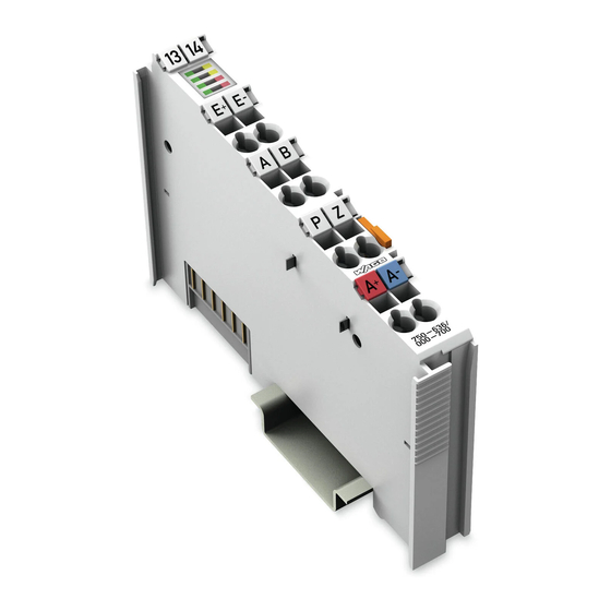
Page 16: View
Figure 1: View Pos : 20.5 /Serie 750 (WAGO-I/O-SYST EM)/Ger ätebesc hrei bung/Ansic ht/Ansic ht C ageCl amp® _Legende mit LEDs , mit 1 Entrieg elungslasc he @ 15\mod_1370867188922_21.doc x @ 122225 @ @ 1 Table 4: Legend for Figure “View”... -
Page 17: Connectors
Figure 2: Data Contacts Pos : 20.9.2 /Serie 750 (WAGO-I/O-SYST EM)/Wichtige Erläuterungen/Sic herheits- und sonstige Hinweis e/Achtung/Achtung: Bus kl emmen nic ht auf Gol dfeder kontakte leg en! @ 7\mod_1266318463636_21.doc x @ 50695 @ @ 1 Do not place the I/O modules on the gold spring contacts! -
Page 18: Power Jumper Contacts/Field Supply
Pos : 20.12.1 /Serie 750 ( WAGO-I/O- SYST EM)/Wic htig e Erl äuter ung en/Sic her hei ts- und s onstige Hi nweise/Vorsicht/Vorsic ht: Verletzungsgefahr durc h sc har fkantige Mes ser kontakte! @ 6\mod_1256193279401_21.doc... - Page 19 WAGO-I/O-SYSTEM 750 Device Description 750-636/000-x00 DC Drive Controller 24V/5A Use supply modules for ground (earth)! The I/O module has no power jumper contacts for receiving and transmitting the earth potential. Use a supply module when an earth potential is needed for the subsequent I/O modules.
-
Page 20: Cage Clamp ® Connectors
Device Description WAGO-I/O-SYSTEM 750 750-636/000-x00 DC Drive Controller 24V/5A Pos : 20.14 /Serie 750 ( WAGO-I/O-SYST EM)/Gerätebeschr eibung/Ansc hlüss e/C AGE C LAMP-Ansc hlüsse - Ü bersc hrift 3 @ 6\mod_1256296337770_21.doc x @ 43674 @ 3 @ 1 ® 3.2.3... -
Page 21: Display Elements
Pos : 20.17 /Alle Serien (Allgemeine M odul e)/Übersc hriften/Ebene 2/Anz eigeelemente - Ü bersc hrift 2 @ 4\mod_1240984390875_21.doc x @ 31964 @ 2 @ 1 Display Elements Pos : 20.18 /Serie 750 ( WAGO-I/O-SYST EM)/Gerätebeschr eibung/Anzeig eel emente/Sonder kl emmen/Anzeigeelemente 750-0636 @ 18\mod_1390482568226_21.doc x @ 143308 @ @ 1 Figure 5: Display Elements Table 7: Legend for Figure “Display Elements”... -
Page 22: Schematic Diagram
Pos : 20.22 /Serie 750 ( WAGO-I/O-SYST EM)/Wichtig e Erl äuter ung en/Sic her hei ts- und s onstige Hinweise/Hinweis/Hi nweis : R üc ks peis ung durch gener atorischen Betri eb @ 18\mod_1390562451027_21.doc x @ 143352 @ @ 1... -
Page 23: Technical Data
Pos : 20.24 /Alle Serien (Allgemeine M odul e)/Übersc hriften/Ebene 2/T ec hnisc he D aten - Übersc hrift 2 @ 3\mod_1232967587687_21.doc x @ 26924 @ 2 @ 1 Technical Data Pos : 20.25 /Serie 750 ( WAGO-I/O-SYST EM)/Gerätebeschr eibung/Tec hnische D aten/Sonder kl emmen/T ec hnisc he D aten 750- 0636/000-700 @ 18\mod_1391516987379_21.doc x @ 144390 @ 333333 @ 1 3.5.1 Device Data Table 1: Technical Data ‒... -
Page 24: Digital Inputs
Device Description WAGO-I/O-SYSTEM 750 750-636/000-x00 DC Drive Controller 24V/5A 3.5.4 Digital Inputs Table 4: Technical Data ‒ Inputs Digital inputs (E+, E-, Preset) Typ1 acc. IEC 61131; high-side switching Input current 2.7 mA at 24 V typ. Input voltage -3 V ... 30 V DC Signal voltage (0) -3 V ... -
Page 25: Figure 7: Start Current
WAGO-I/O-SYSTEM 750 Device Description 750-636/000-x00 DC Drive Controller 24V/5A Inrush current max. The inrush current can be maintained or reduced by setting suitable start and stop ramps. If the maximum inrush current is exceeded, the driver short circuit limitation takes effect in range 1) and a shutdown occurs with the "Overload"... -
Page 26: Connection Type
Pos : 20.28 /Serie 750 ( WAGO-I/O-SYST EM)/Gerätebeschr eibung/Tec hnische D aten/Klimatisc he U mgebungsbeding ungen/T ec hnische D aten Kli mat. U mgebungsbed. ohne erw. T emp. 0...55°C/- 25...+ 85°C @ 5\mod_1247657968368_21.doc x @ 37603 @ 3 @ 1... -
Page 27: Standards And Guidelines
Standards and Guidelines Pos : 20.31 /Serie 750 ( WAGO-I/O-SYST EM)/Gerätebeschr eibung/Nor men und Richtlinien/EMV-N or men Bus klemme 750- xxxx, nur Standardversion - Ei nleitung @ 10\mod_1300282468714_21.doc x @ 70927 @ @ 1 The I/O modules 750-636/000-x00 meet the following requirements on emission and immunity of interference: Pos : 20.32 /Alle Serien (Allgemeine M odul e)/Nor men und Ric htlini en/EM V-Nor men - Standard/EM V C E-Störauss endung EN 61000-6-4 @ 4\mod_1242798273984_21.doc x @ 33602 @ @ 1... -
Page 28: Function Description
Pos : 22 /All e Seri en (Allgemei ne Module)/Ü berschriften/Ebene 1/Funkti onsbesc hrei bung - Ü bersc hrift 1 @ 4\mod_1239025975389_21.doc x @ 30003 @ 1 @ 1 Function Description Pos : 23 /Serie 750 ( WAGO-I/O-SYST EM)/F unktions beschr eibung/Funkti onsbesc hrei bung 750-0636 @ 18\mod_1390898058849_21.doc x @ 143428 @ 223322222223333332233233322 @ 1 Operating Modes and Drive Functions... -
Page 29: Brake Functions
• Short-circuit in the motor final stage • Failure of the field-side 24 V (with versions 750-636/000-700 and 750- 636/000-800 differentiated by motor and logic supply) In this case, the drive is automatically switched off and cannot be restarted until the cause of the error has been resolved. -
Page 30: Operating Modes For Positioning
Function Description WAGO-I/O-SYSTEM 750 750-636/000-x00 DC Drive Controller 24V/5A Operating Modes for Positioning The operating modes for setting the drive are divided into basic and auto mode. The following table illustrates the configuration conditions for the selection of the corresponding operating mode. -
Page 31: Prestop
WAGO-I/O-SYSTEM 750 Function Description 750-636/000-x00 DC Drive Controller 24V/5A Prestop Every drive direction has its own prestop value. The direction-dependent value is considered during the positioning process to determine the stop or deceleration position. If "Optimize_ON" = 1, the prestop is determined at every stop as a function of the braking distance. -
Page 32: Auto Mode
Function Description WAGO-I/O-SYSTEM 750 750-636/000-x00 DC Drive Controller 24V/5A Example 2 Figure 11: Example 2 The braking distance initializes the prestop. The motor turn-off position is below the setpoint position. Due to the prestop, the stop position is exactly the setpoint position. -
Page 33: Positioning With Activated Optimization
WAGO-I/O-SYSTEM 750 Function Description 750-636/000-x00 DC Drive Controller 24V/5A 4.9.1 Positioning with Activated Optimization Example 4: Figure 13: Example 4 Zero (0) initializes the prestop for the Up direction. The motor turn-off position equals the setpoint position. The setpoint position is overtravelled by the braking distance and, due to the enabled optimization, the braking distance in the Up direction initializes the prestop. -
Page 34: Positioning With Enabled Optimization And Retry Not Equal To 0 (Loop Traverse)
Function Description WAGO-I/O-SYSTEM 750 750-636/000-x00 DC Drive Controller 24V/5A 4.9.2 Positioning with Enabled Optimization and Retry Not Equal to 0 (Loop Traverse) Example 6: Figure 15: Example 6 Zero (0) initializes the prestop for the Up and Down directions and the actual position is below the setpoint position. -
Page 35: Positioning With Enabled Optimization And Too Short Distance
WAGO-I/O-SYSTEM 750 Function Description 750-636/000-x00 DC Drive Controller 24V/5A 4.9.3 Positioning with Enabled Optimization and too Short Distance Example 7: Figure 16: Example 7 The prestops for the Up and Down direction are initialized and the actual position is below the setpoint position. It is now detected that the distance to the setpoint position is too short to be reached directly. -
Page 36: Positioning With Negatively Initialized Overtravel
Function Description WAGO-I/O-SYSTEM 750 750-636/000-x00 DC Drive Controller 24V/5A 4.9.4 Positioning with Negatively Initialized Overtravel Example 8: Figure 17: Example 8 The negatively initialized overtravel forces the setpoint position to be approached from below. The approach position is generated by adding setpoint position (SP) and overtravel (OT). -
Page 37: Positioning With Positively Initialized Overtravel
WAGO-I/O-SYSTEM 750 Function Description 750-636/000-x00 DC Drive Controller 24V/5A 4.9.5 Positioning with Positively Initialized Overtravel Example 10: Figure 19: Example 10 The positively initialized overtravel forces the setpoint position to be approached from above. As the actual position is further above the setpoint position than the absolute value of the overtravel, the setpoint position can be reached within the first motion cycle. -
Page 38: Positioning With Negatively Initialized Overtravel At Too Little Distance
Function Description WAGO-I/O-SYSTEM 750 750-636/000-x00 DC Drive Controller 24V/5A 4.9.6 Positioning with Negatively Initialized Overtravel at Too Little Distance Example 12: Figure 21: Example 12 The negatively initialized overtravel forces the setpoint position to be approached from below. It is detected that the distance to the setpoint position is smaller than the absolute value of the overtravel. -
Page 39: Setpoint Change On The Fly
WAGO-I/O-SYSTEM 750 Function Description 750-636/000-x00 DC Drive Controller 24V/5A 4.10 Setpoint Change on the Fly If during an active positioning motion the setpoint position is changed in the process image, the I/O module should react. If this new setpoint position is in direction of the motion, the I/O module will attempt to reach this position with an intermediate stop. -
Page 40: Pwm Control During Positioning
Function Description WAGO-I/O-SYSTEM 750 750-636/000-x00 DC Drive Controller 24V/5A 4.11 PWM Control during Positioning 4.11.1 General It is possible to enable PWM control independently of the drive mode. Basically, PWM control will have no impact on the direction and the number of moving cycles during the positioning process. -
Page 41: Drive Versions Including Change To Lower Speed
WAGO-I/O-SYSTEM 750 Function Description 750-636/000-x00 DC Drive Controller 24V/5A The duration of phase P3 results from the total duration and the subtraction of all other phases: P3 = Ptot –(P1 + P2 + P4 + P5). A waypoint in the direction of travel before the setpoint position determines the start of phase P4. -
Page 42: Figure 26: Example 16, "Shutdown_Distance Is Reached In Phase P2
Function Description WAGO-I/O-SYSTEM 750 750-636/000-x00 DC Drive Controller 24V/5A Example 16 "ShutDown_Distance is reached in phase P2": Figure 26: Example 16, "ShutDown_Distance is Reached in Phase P2" The waypoint that starts phase 4, which is defined by the ShutDown_Distance, is reached before phase P2 is completed. -
Page 43: Figure 28: Example 18, " Approach Without Currentcontrol_Pwm
WAGO-I/O-SYSTEM 750 Function Description 750-636/000-x00 DC Drive Controller 24V/5A Example 18 "Approach without CurrentControl_PWM": Figure 28: Example 18, " Approach without CurrentControl_PWM" A positioning operation without phase P4 or CurrentControl is possible if the ShutDown_Distance value is set to 0. Another reason for the absence of phase P4 could be that the direction-dependent prestop is at least the length of the configured ShutDown_Distance (ShutDown_Distance <= Prestop). -
Page 44: Figure 30: Example 20, "Approach With Currentcontrol_Pwm
Function Description WAGO-I/O-SYSTEM 750 750-636/000-x00 DC Drive Controller 24V/5A Example 20, "Approach with CurrentControl_PWM = f(Control.CurrentControl_ON), Version 2": Figure 30: Example 20, "Approach with CurrentControl_PWM = f(Control.CurrentControl_ON), Version 2" CurrentControl_ON=2 is already set during phase P1. Phase P2 must not be interrupted prematurely as shown in example 16 (ShutDown_Distance in P2). -
Page 45: Swing-Back Drives With Subsequent Setpoint Position Drive
WAGO-I/O-SYSTEM 750 Function Description 750-636/000-x00 DC Drive Controller 24V/5A 4.12 Swing-Back Drives with Subsequent Setpoint Position Drive The I/O module only starts a braking process from the CurrentControl_PWM or the maximum speed, but never from the CurrentLimit_PWM. This should be taken into account when designing the project. -
Page 46: Calculating The Acceleration Distance
Function Description WAGO-I/O-SYSTEM 750 750-636/000-x00 DC Drive Controller 24V/5A is not stopped from 100% PWM, but always from CurrentControl_PWM. The shortest executed swing-back drive is represented in the graphic below (blue line). Figure 32: Braking from CurrentControl_PWM (CurrentControl_PWM > CurrentLimit_PWM) If CurrentControl_PWM is smaller than CurrentLimit_PWM, then the drive travels during the acceleration phase P2 with CurrentControl_PWM. -
Page 47: Calculating A Swing-Back Drive
WAGO-I/O-SYSTEM 750 Function Description 750-636/000-x00 DC Drive Controller 24V/5A 4.12.3 Calculating a Swing-Back Drive The target position of a swing-back drive is determined relative to the setpoint position and the distance to the setpoint position is calculated from the sum of the acceleration and braking distance (plus 10% safety margin). -
Page 48: Standstill Condition
Function Description WAGO-I/O-SYSTEM 750 750-636/000-x00 DC Drive Controller 24V/5A 4.13 Standstill Condition While processing the motion command, the brake path of the drive is determined at every stop. The brake path is always concluded, when the I/O module detects the standstill of the motor due to missing rotary transducer impulses. In addition, the standstill evaluation is also executed in the inactive positioning cycle. -
Page 49: Figure 35: Standstill Condition
WAGO-I/O-SYSTEM 750 Function Description 750-636/000-x00 DC Drive Controller 24V/5A Example: 2 pulses per acquisition interval Figure 35: Standstill Condition Relative to positioning quality, smaller limit values lead to smaller positioning errors (especially with a large centrifugal mass or encoders that have a higher resolution), but also to a longer total time for the positioning operation. -
Page 50: Maximum Pulse Frequency Of The Incremental Encoder
Function Description WAGO-I/O-SYSTEM 750 750-636/000-x00 DC Drive Controller 24V/5A 4.14 Maximum Pulse Frequency of the Incremental Encoder Common 24 V DC collector motors normally have a maximum speed of approx. 4,600 min . Common incremental encoders provide 1 to max. 10,000 pulses/rev. -
Page 51: Mounting
I/O modules with fewer power contacts. Pos : 26.2 /Serie 750 (WAGO-I/O-SYST EM)/Wic htige Erläuterungen/Sicherheits- und sonstig e Hinweis e/Vorsic ht/Vorsicht: Verl etz ungsgefahr durc h s charfkantige M ess er kontakte! @ 6\mod_1256193279401_21.doc x @ 43414 @ @ 1 Risk of injury due to sharp-edged blade contacts! The blade contacts are sharp-edged. -
Page 52: Inserting And Removing Devices
Working on energized devices can damage them. Therefore, turn off the power supply before working on the devices. Pos : 26.8 /Serie 750 (WAGO-I/O-SYST EM)/M ontieren/D emontieren/I/O-Modul einfüg en @ 3\mod_1231769726703_21.doc x @ 25989 @ 3 @ 1 5.2.1 Inserting the I/O Module... -
Page 53: Removing The I/O Module
WAGO-I/O-SYSTEM 750 Mounting 750-636/000-x00 DC Drive Controller 24V/5A Pos : 26.10 /Serie 750 ( WAGO-I/O-SYST EM)/Monti eren/D emonti eren/I/O-M odul entfer nen @ 4\mod_1239169375203_21.doc x @ 30334 @ 3 @ 1 5.2.2 Removing the I/O Module Remove the I/O module from the assembly by pulling the release tab. -
Page 54: Connect Devices
Connect Devices Pos : 29 /Serie 750 ( WAGO-I/O-SYST EM)/Ans chli eßen/Leiter an C AGE C LAM P ans chli eßen ( allgemei n) - Übersc hrift 2 und Text @ 3\mod_1225448660171_21.doc x @ 24928 @ 2 @ 1 ®... -
Page 55: Process Image
Process Image Pos : 32 /Serie 750 ( WAGO-I/O-SYST EM)/Proz ess abbild Kl emmenbus /Hinweis: Prozes sabbildmapping abhängig von FBK/PFC, ohne Status-/C ontr olbyte @ 6\mod_1256126797251_21.doc x @ 43340 @ @ 1 Mapping of process data in the process image of fieldbus systems The representation of the process data of some I/O modules or their variants in the process image depends on the fieldbus coupler/controller used. -
Page 56: Control Bytes And Status Bytes
Process Image WAGO-I/O-SYSTEM 750 750-636/000-x00 DC Drive Controller 24V/5A Control Bytes and Status Bytes Table 19: Control Byte C0 Control Byte C0 Bit 7 Bit 6 Bit 5 Bit 4 Bit 3 Bit 2 Bit 1 Bit 0 Current Preset... - Page 57 WAGO-I/O-SYSTEM 750 Process Image 750-636/000-x00 DC Drive Controller 24V/5A Table 20: Control Byte C1 Control Byte C1 Bit 7 Bit 6 Bit 5 Bit 4 Bit 3 Bit 2 Bit 1 Bit 0 Error_Qui Extended Optimize Preset Info_On Input _Enable...
-
Page 58: Table 21: Status Byte S0
Process Image WAGO-I/O-SYSTEM 750 750-636/000-x00 DC Drive Controller 24V/5A Table 21: Status Byte S0 Status Byte S0 Bit 7 Bit 6 Bit 5 Bit 4 Bit 3 Bit 2 Bit 1 Bit 0 Error Refer Standstill Busy OnTarget Move Move... - Page 59 WAGO-I/O-SYSTEM 750 Process Image 750-636/000-x00 DC Drive Controller 24V/5A Table 22: Status Byte S1 Status Byte S1 Bit 7 Bit 6 Bit 5 Bit 4 Bit 3 Bit 2 Bit 1 Bit 0 Limit Limit Preset Current PWM_Act Extended Optimize...
-
Page 60: Extended Status Bytes
Process Image WAGO-I/O-SYSTEM 750 750-636/000-x00 DC Drive Controller 24V/5A Extended Status Bytes Table 23: Extended Status Byte S2 Extended Status Byte S2 Bit 7 Bit 6 Bit 5 Bit 4 Bit 3 Bit 2 Bit 1 Bit 0 24V_ Param... -
Page 61: Process Image For Register Communication
Bit 0 Reserved Pos : 34 /Serie 750 ( WAGO-I/O-SYST EM)/Proz ess abbild Kl emmenbus /Sonder klemmen/Pr ozessabbild 750- 0636_R egister kommuni kati on @ 18\mod_1391420071154_21.doc x @ 144218 @ 2 @ 1 Process Image for Register Communication If bit 2^7 of control byte C0 is set to the value 1, the I/O module responds by setting bit 2^7 of status byte S0 to the value 1. -
Page 62: Table 28: Meaning Of The Process Image For Register Communication
Process Image WAGO-I/O-SYSTEM 750 750-636/000-x00 DC Drive Controller 24V/5A Table 28: Meaning of the Process Image for Register Communication Description Explanation REG_C Control byte of register communication REG_S Status byte of register communication REG_D0 Lower byte (LSB) of a register value read by the I/O module... -
Page 63: Parameterizing
(see ch. "Parameterize" > "Parameter Data Sets", "Parameter Channel" and "Register Communication"). Pos : 36.3 /Serie 750 (WAGO-I/O-SYST EM)/In Betrieb nehmen/Parametrier en über Parameter kanal/Parametrier en 750-0636_Register kommuni kation @ 18\mod_1391166786422_21.doc x @ 144088 @ 2 @ 1 Register Communication Some I/O modules of the 750 series offer a protocol subsequently referred to as "register communication"... -
Page 64: Table 29: Assignment Of Control Byte Reg_C For Register Communication
Parameterizing WAGO-I/O-SYSTEM 750 750-636/000-x00 DC Drive Controller 24V/5A the previous request, the D0 and D1 bytes of the PAE then receive the current value of the respective register. Bits 0 ... 5 of control byte REG_C receive the register number. The access direction (read/write) is set via bit 6 (R/W) of control byte REG_C. - Page 65 WAGO-I/O-SYSTEM 750 Parameterizing 750-636/000-x00 DC Drive Controller 24V/5A Do not forget: reset password! Password register 31 retains written values until the power supply is switched off next. Therefore, specify password register 31 with "0x0000", once you have completed all pending changes to registers. This restores protection against accidental changes for all password-protected registers! Pos : 36.4 /Dokumentation allgemei n/Glieder ungs elemente/---Seitenwechs el--- @ 3\mod_1221108045078_0.doc x @ 21810 @ @ 1...
-
Page 66: Parameter Records
Parameterizing WAGO-I/O-SYSTEM 750 750-636/000-x00 DC Drive Controller 24V/5A Pos : 36.5 /Serie 750 (WAGO-I/O-SYST EM)/In Betrieb nehmen/Parametrier en über Parameter kanal/Parametrier en 750-0636_Parameter-Datensätz e @ 18\mod_1391170590486_21.doc x @ 144092 @ 23444334443444 @ 1 Parameter Records 8.2.1 Available Parameter Records The I/O module has three different parameter records. -
Page 67: Password Protection
The I/O module does not automatically reset passwords. Without another write command to register 31, they will remain valid until the power down! The parameter data set Factory Default (3) may be only modified by WAGO Kontakttechnik GmbH & Co. KG. -
Page 68: User Settings (2)
Factory Default (3) The parameter data set Factory Default (3) may be only modified (written/changed, etc.) by WAGO Kontakttechnik GmbH & Co. KG. The parameter data set Factory Default (3) will be transferred to the volatile memory area of the module; i.e., to the parameter set Actual (1), via REQ_RESTORE_FACTORY command, which will then be entered into register 3 of the module. -
Page 69: Command Overview
WAGO-I/O-SYSTEM 750 Parameterizing 750-636/000-x00 DC Drive Controller 24V/5A 8.2.4.3 Command Overview The following tables show the relevant commands for register 3 and the expected corresponding acknowledgement data in register 4, for both a positive and negative acknowledgement. Table 33: Command Overview 1 Command (request reg. -
Page 70: Parameter Channel
WAGO-I/O-SYSTEM 750 750-636/000-x00 DC Drive Controller 24V/5A Pos : 36.7 /Serie 750 (WAGO-I/O-SYST EM)/In Betrieb nehmen/Parametrier en über Parameter kanal/Parametrier en 750-0636_Parameter kanal @ 18\mod_1391422708725_21.doc x @ 144221 @ 233 @ 1 Parameter Channel Some I/O modules of the 750 series offer a protocol subsequently referred to as "parameter channel"... -
Page 71: Table 36: Register 57
WAGO-I/O-SYSTEM 750 Parameterizing 750-636/000-x00 DC Drive Controller 24V/5A Table 36: Register 57 Register 57 Request parameters Response parameter Request TGL_ PRM_ MORE_ parameters Response TGL_ TIME BUF_ PRM_ parameter Request parameter: Information is written by the application and read by the I/O module. -
Page 72: 750-636/000-X00 Dc Drive Controller 24V/5A
WAGO-I/O-SYSTEM 750 750-636/000-x00 DC Drive Controller 24V/5A Pos : 36.9 /Serie 750 (WAGO-I/O-SYST EM)/In Betrieb nehmen/Parametrier en über Parameter kanal/Parametrier en 750-0636_Ablauf der Par ameter übertrag ung @ 18\mod_1391173018836_21.doc x @ 144158 @ 2 @ 1 Process of Parameter Transmission Parameter data exchange between the application and I/O module is made via request/response process. -
Page 73: General Parameter Data (System Parameter Range)
750-636/000-x00 DC Drive Controller 24V/5A Pos : 36.11 /Serie 750 ( WAGO-I/O-SYST EM)/In Betri eb nehmen/Par ametrieren über Par ameter kanal/Parametrier en 750- 0636_Allgemei ne Parameterdaten @ 18\mod_1391523041189_21.doc x @ 144407 @ 2 @ 1 General Parameter Data (System Parameter Range) Defined parameters indexed via parameter addresses configure the I/O module with the parameter channel. -
Page 74: I/O Module-Specific Parameter Data
750-636/000-x00 DC Drive Controller 24V/5A Pos : 36.13 /Serie 750 ( WAGO-I/O-SYST EM)/In Betri eb nehmen/Par ametrieren über Par ameter kanal/Parametrier en 750- 0636_I/O-M odul-spezifis che Par ameter daten @ 18\mod_1391416278710_21.doc x @ 144194 @ 23333333333333333 @ 1 I/O Module-Specific Parameter Data... -
Page 75: Ramptime_Start, Ramptime_Stop
WAGO-I/O-SYSTEM 750 Parameterizing 750-636/000-x00 DC Drive Controller 24V/5A Parameter Parameters Description Register Address Brake-Mode Selection of Brake mode Stop-Mode_Entry Transition to Stop mode Increase_Swing_Back Extending a swing-back drive Reflection of information given in the Extended_Infos expanded status bytes S2 and S3... -
Page 76: Prestop_Pos
Parameterizing WAGO-I/O-SYSTEM 750 750-636/000-x00 DC Drive Controller 24V/5A 8.6.2 Prestop_Pos Table 40: 2.2.2 Prestop_Pos Factory default Parameter address Function Access setting Prestop_Pos 0x0064 Prestop value positive direction [0 ... 65535] The configured value determines the prestop value to be used for optimization during a positioning operation in a positive direction if the option is enabled in the control byte of the process image. -
Page 77: Z_Input_Enable, Stop-Mode_Pwrup
5 pulse/s Bit 6: Reserved Bit 7: EnginePowerSupply (only 750-636/000-700) The I/O module can be operated at motor operating voltage levels less than 24 V when this bit is set. In this case, motor voltage monitoring is de-activated. Motor voltage = 24 V Motor voltage <... -
Page 78: Presetvalue
Parameterizing WAGO-I/O-SYSTEM 750 750-636/000-x00 DC Drive Controller 24V/5A Factory default Parameter address Function Access setting Preset function via the Preset input and the Z input. During the active signal for the Preset input, the Preset value is assumed at the actual position when an edge is detected at the Z input. -
Page 79: Triggermode_Inputs, Stop-Mode, Directionreversal_Delay
WAGO-I/O-SYSTEM 750 Parameterizing 750-636/000-x00 DC Drive Controller 24V/5A 8.6.8 TriggerMode_Inputs, Stop-Mode, DirectionReversal_Delay Table 46: 2.2.3 TriggerMode_Inputs, Stop-Mode, DirectionReversal_Delay Factory default Parameter address Function Access setting TriggerMode_Inputs 0x0A37 Stop-Mode DirectionReversal_Delay Bit 0 ... 3: TriggerMode_Inputs Input sensitivity of the digital inputs... -
Page 80: Filter_Time
Parameterizing WAGO-I/O-SYSTEM 750 750-636/000-x00 DC Drive Controller 24V/5A Factory default Parameter address Function Access setting Bit 8 ... 15: DirectionReversal_Delay [0 ... 255] The motor interface delays the power-up procedure for n times 10 ms in case of rotation direction reversal. -
Page 81: Shutdown_Distance
WAGO-I/O-SYSTEM 750 Parameterizing 750-636/000-x00 DC Drive Controller 24V/5A 8.6.10 ShutDown_Distance Table 48: 2.2.3 ShutDown_Distance Factory default Parameter address Function Access setting ShutDown_Distance (HighWord) 0x0000 ShutDown_Distance (LowWord) 0x0000 ShutDown_Distance During a positioning operation, it is possible to induce CurrentControl_PWM at the final motor stage n increments before reaching the setpoint position. -
Page 82: Currentlimit_Pwm, Currentcontrol_Pwm
Parameterizing WAGO-I/O-SYSTEM 750 750-636/000-x00 DC Drive Controller 24V/5A 8.6.11 CurrentLimit_PWM, CurrentControl_PWM Table 49: 2.2.3 CurrentLimit_PWM, CurrentControl_PWM Factory default Parameter address Function Access setting CurrentLimit_PWM 0xB4AF CurrentControl_PWM Bit 0 ... 7: CurrentLimit_PWM [0 ... 200] CurrentLimit_PWM configures a pulse-duty factor for the PWM signal for motor control. -
Page 83: Currentlimit_Time, Motiondetectiontimeout
WAGO-I/O-SYSTEM 750 Parameterizing 750-636/000-x00 DC Drive Controller 24V/5A 8.6.12 CurrentLimit_Time, MotionDetectionTimeout Table 50: 2.2.3 CurrentLimit_Time, MotionDetectionTimeout Factory default Parameter address Function Access setting CurrentLimit_Time 0x0000 MotionDetectionTimeout Bit 0 ... 7: CurrentLimit_Time [0 ... 255] CurrentLimit_Time determines the CurrentLimit_PWM ON time at n times 100 ms during a positioning operation with PWM. -
Page 84: Brake-Mode, Stop-Mode_Entry, Encoder_Limit_Frequency
Parameterizing WAGO-I/O-SYSTEM 750 750-636/000-x00 DC Drive Controller 24V/5A 8.6.13 Brake-Mode, Stop-Mode_Entry, Encoder_Limit_Frequency Table 51: 2.2.3 Brake-Mode, Stop-Mode_Entry, Encoder_Limit_Frequency Factory default Parameter address Function Access setting Brake-Mode Stop-Mode_Entry, 0x0105 Encoder_Limit_Frequency Bit 0 ... 5: Brake-Mode The brake mode determines the brake properties for the motor control. The brake mode distinguishes between Idle, PWM ramp and Brake. -
Page 85: Increase_Swing_Back
WAGO-I/O-SYSTEM 750 Parameterizing 750-636/000-x00 DC Drive Controller 24V/5A 8.6.14 Increase_Swing_Back Table 52: 2.2.3 Increase_Swing_Back Factory default Parameter address Function Access setting Increase_Swing_Back 0x0000 Bit 0 ... 7: Increase_Swing_Back [0 ... 255] This value is indicated as a percentage at a resolution of 10% within a range of 0 to 2550% for extending a swing-back drive during positioning. -
Page 86: Extended_Infos
Bit 3: 24 V_OK (depending on the I/O module used) The 24 V field power supply has failed. (only for 750-636) A 24 V power supply system has failed. (only for 750-636/000-700) The 24 V field power supply is available. (only for 750-636) Both 24 V power supply systems are available. -
Page 87: Swing_Back_Distance
WAGO-I/O-SYSTEM 750 Parameterizing 750-636/000-x00 DC Drive Controller 24V/5A 8.6.16 Swing_Back_Distance Table 54: 2.2.3 Swing_Back_Distance Factory default Parameter address Function Access setting Swing_Back_Distance 0x0000 Display of current swing-back distance. The value format corresponds to a 16 bit wide integer value with sign, in the value range between -32768 (0x8000) and +32767 (0x7FFF). -
Page 88: Using Interference-Free Variations Of I/O Modules In Safety Related Applications
750-636/000-x00 DC Drive Controller 24V/5A Pos : 38.1 /Serie 750 (WAGO-I/O-SYST EM)/Eins atz in sicherheitsg erichteten Anwendung en/Ei nleitung - r üc kwir kungsfr eie Varianten 750-636 @ 18\mod_1392711972256_21.doc x @ 145722 @ 1 @ 1 Using Interference-Free Variations of I/O Modules in Safety Related Applications The variation 750-636/xxx-8xx of the I/O module 750-636 (designation “... -
Page 89: Important Notes
750-636/000-x00 DC Drive Controller 24V/5A Pos : 38.4 /Serie 750 (WAGO-I/O-SYST EM)/Eins atz in sicherheitsg erichteten Anwendung en/Hi nweise zum Ei nsatz i n Sicherheits anwendungen @ 6\mod_1258974811438_21.doc x @ 44688 @ 2 @ 1 Eins atz der rüc kwir kungsfrei en Digital ausg angs kl emme in Sic her heitsanwendungen... -
Page 90: Connecting The I/O Module To Safety Switching Devices Or F I/O Modules
750-636/000-800 I/O module! Pos : 38.6 /Serie 750 (WAGO-I/O-SYST EM)/Eins atz in sicherheitsg erichteten Anwendung en/Allgemeiner Aufbau ei ner Potenti algruppe - r üc kwir kungsfr eie Vari anten @ 6\mod_1258973074755_21.doc x @ 44664 @ 23 @ 1... -
Page 91: Example Of Connection
750-636/000-x00 DC Drive Controller 24V/5A Pos : 40 /Serie 750 ( WAGO-I/O-SYST EM)/Eins atz in sicherheitsg erichteten Anwendung en/Ansc hluss beispi ele/Ansc hlussbeis piel 2/4-Kanal-Digital ausg angs kl emmen i n Sicherheits anwendungen-750- 636/000- 800 @ 30\mod_1501138006549_21.doc x @ 456639 @ 3 @ 1 Eins atz der rüc kwir kungsfrei en Digital ausg angs kl emme in Sic her heitsanwendungen... -
Page 92: List Of Figures
List of Figures WAGO-I/O-SYSTEM 750 750-636/000-x00 DC Drive Controller 24V/5A Pos : 42 /D okumentation allgemei n/Verz eic hniss e/Abbil dungs verz eic hnis - Übersc hrift oG und Verz eichnis @ 3\mod_1219222916765_21.doc x @ 21080 @ @ 1 List of Figures Figure 1: View ....................... - Page 93 WAGO-I/O-SYSTEM 750 List of Figures 750-636/000-x00 DC Drive Controller 24V/5A Pos : 43 /D okumentation allgemei n/Glieder ungs elemente/---Seitenwechs el--- @ 3\mod_1221108045078_0.doc x @ 21810 @ @ 1 Manual Version 2.1.0...
-
Page 94: List Of Tables
List of Tables WAGO-I/O-SYSTEM 750 750-636/000-x00 DC Drive Controller 24V/5A Pos : 44 /D okumentation allgemei n/Verz eic hniss e/Tabell enverz eichnis - Übersc hrift oG und Verz eichnis @ 3\mod_1219222958703_21.doc x @ 21084 @ @ 1 List of Tables Table 1: Variants ..................... - Page 95 WAGO-I/O-SYSTEM 750 List of Tables 750-636/000-x00 DC Drive Controller 24V/5A Table 49: 2.2.3 CurrentLimit_PWM, CurrentControl_PWM ......82 Table 50: 2.2.3 CurrentLimit_Time, MotionDetectionTimeout ......83 Table 51: 2.2.3 Brake-Mode, Stop-Mode_Entry, Encoder_Limit_Frequency .. 84 Table 52: 2.2.3 Increase_Swing_Back ............... 85 Table 53: 2.2.3 Extended_Infos ................. 86 Table 54: 2.2.3 Swing_Back_Distance ..............
- Page 96 Pos : 46 /D okumentation allgemei n/Einband/Einband H andbuc h - R üc kseite 2015 @ 9\mod_1285229376516_21.doc x @ 64944 @ @ 1 WAGO Kontakttechnik GmbH & Co. KG Postfach 2880 • D-32385 Minden Hansastraße 27 • D-32423 Minden Phone: 05 71/8 87 –...
Need help?
Do you have a question about the 750-636/000-700 and is the answer not in the manual?
Questions and answers