Table of Contents
Advertisement
Quick Links
Advertisement
Table of Contents

Related Manuals for Keysight V3500A


Summary of Contents for Keysight V3500A
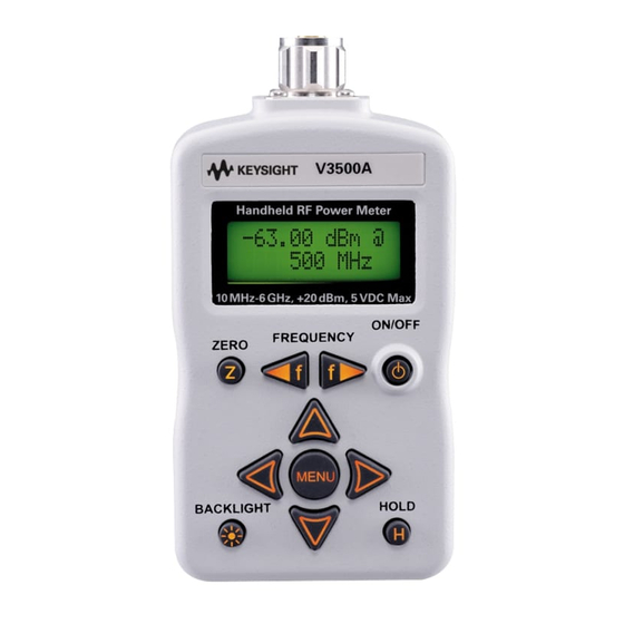
- Page 1 Keysight V3500A Handheld RF Power Meter User’s Guide...
-
Page 4: Safety Notices
1400 Fountaingrove Parkway performance of this document or of Santa Rosa, CA 95403 any information contained herein. Should Keysight and the user have a Trademark Acknowledgements separate written agreement with WA R N I N G Microsoft, Visual Studio, and Windows are warranty terms covering the material U.S. -
Page 5: Safety Symbols
Caution, risk of danger (refer to this manual Earth (ground) terminal for specific Warning or Caution information) Caution, hot surface Protective conductor terminal Frame or chassis terminal Out position of a bi-stable push control Equipotentiality In position of a bi-stable push control V3500A User’s Guide... -
Page 6: General Safety Information
Keysight Technologies assumes no liability for the customer’s failure to comply with these requirements. • Observe all markings on the instrument before connecting any wiring WA R N I N G to the instrument. -
Page 7: Environmental Conditions
–10 °C to 70 °C Altitude Up to 2000 meters Pollution degree Pollution Degree 2 • The Keysight V3500A complies with the following safety and EMC C A U T I O N requirements: • IEC 61326-2-1:2005/ EN 61326-2-1:2006 •... - Page 8 Canadian requirement. This affixed product label ICES-001. indicates that you must not discard Cet appareil ISM est confomre a la this electrical or electronic product in norme NMB-001 du Canada. domestic household waste. V3500A User’s Guide...
- Page 9 “Monitoring and Control Instrument” product. The affixed product label is as shown below. Do not dispose in domestic household waste To return this unwanted instrument, contact your nearest Keysight Technologies, or visit: www.keysight.com/environment/product for more information.
- Page 10 In This Guide… Getting Started This chapter introduces the key features of the V3500A Handheld RF Power Meter and prepares the power meter for initial setup. Knowing your Instrument This chapter specifies the characteristics, environmental conditions, and specifications of the V3500A Handheld RF Power Meter. This chapter contains a brief description of the instrument outlook, front panel operation, and front panel procedure.
- Page 11 The Declaration of Conformity (DoC) for this instrument is available on the Web site. You can search the DoC by its instrument model or description. http://www.keysight.com/go/conformity If you are unable to search for the respective DoC, please contact your N O T E local Keysight representative. V3500A User’s Guide...
- Page 12 THIS PAGE HAS BEEN INTENTIONALLY LEFT BLANK. V3500A User’s Guide...
-
Page 13: Table Of Contents
Knowing your Instrument Product at a Glance Product dimensions The front panel keypad How to navigate the menu system How to power on the V3500A Front panel operations Measuring power Zeroing the power meter Setting the input frequency Setting the measurement speed... - Page 14 Installing programming driver Instrument Address Remote USB Operation Introduction Bus connections Remote USB commands Basic driver commands Basic V3500A commands Averaging control commands Measurement speed control commands Unit of measurement commands Relative Offset Commands Miscellaneous commands Examples RF Measurement Basics...
- Page 15 High frequency method Power of various types of signals Measurement accuracy Characteristics and Specifications Product Characteristics Product Specifications V3500A User’s Guide XIII...
- Page 16 THIS PAGE HAS BEEN INTENTIONALLY LEFT BLANK. V3500A User’s Guide...
- Page 17 List of Figures Figure 1-1 V3500A Handheld RF Power Meter with backlight turned on 2 Figure 1-2 V3500A with Type-N connector nut 5 Figure 1-3 Full serial number, USB type mini-B port, and external power connector 7 Figure 2-1 V3500A dimensions 10...
- Page 18 THIS PAGE HAS BEEN INTENTIONALLY LEFT BLANK. V3500A User’s Guide...
- Page 19 List of Tables Table 2-1 V3500A keypad functions 11 Table 2-2 Menu map structure description 14 Table 3-1 SETAVG command values 56 Table 5-1 SWR performance for different frequency band 98 V3500A User’s Guide XVII...
- Page 20 THIS PAGE HAS BEEN INTENTIONALLY LEFT BLANK. XVIII V3500A User’s Guide...
-
Page 21: Getting Started
Optional purchase items 4 Handling Precaution 4 Setting-up your Instrument 5 Connectivity 5 RF connector 5 USB port 7 Power supply 8 This chapter introduces the key features of the V3500A Handheld RF Power Meter and prepares the power meter for initial setup. -
Page 22: Introduction
For use in the field, the compact size of the V3500A allows it to be placed in a toolkit. You do not have to carry both a power meter and a separate sensor module (the V3500A has a built- in sensor) when conducting measurement in the field. -
Page 23: Key Features
If any damage is found, notify the nearest Keysight Sales Office immediately. The front of this manual contains the warranty information. -
Page 24: Optional Purchase Items
✔ Printed Keysight V3500A Handheld RF Power Meter, 10 MHz to 6 GHz User’s Guide (English) (V3500A- ABA) Keep the original packaging in case the V3500A has to be returned to Keysight in the future. Also, include a brief description of the problem. -
Page 25: Setting-Up Your Instrument
RF connector Use the Type- N male RF connector with 50 Ω characteristic impedance (see Figure 1- 2) to make RF signal connections. Type-N male connector nut Figure 1-2 V3500A with Type-N connector nut V3500A User’s Guide... - Page 26 It is important to turn the nut of the connector rather than the body of the power meter when tightening the connection. When connecting the Type-N connector of the V3500A to a Type-N female N O T E connector for a power measurement, observe proper practice for tightening the connection.
-
Page 27: Figure 1-3 Full Serial Number, Usb Type Mini-B Port, And External Power Connector
Getting Started USB port The V3500A has a USB 2.0 interface with mini- B port (see Figure 1- 3). The V3500A can be remotely programmed over this USB interface. In addition to remote programming, the V3500A can be powered by the USB port regardless of whether the batteries are present or connected to the external power supply (V3500A- PWR). -
Page 28: Power Supply
You can use either the battery power or the external power connector to power on your V3500A. • Battery power The V3500A can be powered by two AA batteries. If installed, the batteries will power the V3500A only if the external power supply and USB are not connected. -
Page 29: Knowing Your Instrument
Setting the backlight auto-shutoff interval 22 Using relative offset function 23 This chapter specifies the characteristics, environmental conditions, and specifications of the V3500A Handheld RF Power Meter. This chapter contains a brief description of the instrument outlook, front panel operation, and front panel... -
Page 30: Product At A Glance
Knowing your Instrument Product at a Glance Product dimensions 1134 mm 49 mm 79 mm Figure 2-1 V3500A dimensions V3500A User’s Guide... -
Page 31: The Front Panel Keypad
Table 2-1 V3500A keypad functions Description Press ZERO to measure the offset voltages in the signal path and zero the V3500A. This allows a more accurate measurement at low power levels. The V3500A RF input may be left disconnected when it is zeroed, or it may be connected to other hardware, but make sure that no signals are present on the RF input as this results in inaccurate readings. - Page 32 Press HOLD for the most recent reading to be frozen on the display and is no longer updated. This allows the user to disconnect the V3500A from the source and then read the display. Press HOLD again to disable the hold function and the display will once again be updated continuously.
-
Page 33: How To Navigate The Menu System
The menu map structure is shown in Figure 2- 3 and the description is shown in Table 2- 2. The menu items in <> brackets are the default menu values. Figure 2-3 Menu map structure V3500A User’s Guide... -
Page 34: Table 2-2 Menu Map Structure Description
Refer to “Using relative offset function” on page The numerical serial number displayed on the instrument is for reference only. For full serial number (with prefix), please refer to the printed label shown in Figure 1-3 on page V3500A User’s Guide... - Page 35 2 In the “AVERAGING” menu, the left and right menu keypads can turn averaging “Off” or select 2, 4, 8, 16, or 32 averages. If the present selection is <2>, and the right menu key is pressed, the active selection will be changed to <4> immediately. V3500A User’s Guide...
-
Page 36: How To Power On The V3500A
Knowing your Instrument How to power on the V3500A Use the ON/OFF keypad to turn on or turn off the V3500A. While operating on battery power, the V3500A has a power auto- shutoff feature to preserve battery life. This feature automatically turns the power meter off after a certain duration. -
Page 37: Front Panel Operations
2 Zero the V3500A. Refer to “Zeroing the power meter” on page 18 for more information. 3 Connect the V3500A RF input port to the signal to be measured. Refer to “RF connector” on page 5 for more information. The top line of the display shows the measured power of the signal. -
Page 38: Zeroing The Power Meter
The V3500A should be zeroed when it warms up, and periodically when the ambient temperature changes. 1 Prior to zeroing the V3500A, make sure all the RF power is removed from the V3500A RF input port. This can be done by disconnecting the RF input, or by disabling the output of any signal sources connected to V3500A. -
Page 39: Setting The Measurement Speed
Knowing your Instrument Setting the measurement speed In normal operation speed, the V3500A will complete a power measurement in about 1 second (± 0.5 second depending on the power level of the input signal). Lower level signals take longer to measure than higher level signals. -
Page 40: Saving The Instrument State
N O T E Recalling the instrument state restores all stored menu values in the V3500A non-volatile memory. Frequency settings are not recalled. 1 Press MENU to enter menu mode. 2 Scroll using the down menu arrow keypad until “Recall State”... -
Page 41: Setting Units: Dbm Or Watts
V3500A. Setting units: dBm or watts • When operating the V3500A in Watts mode using the front panel, it will N O T E display nW, µW, mW, or W accordingly. -
Page 42: Controlling The Backlight
Knowing your Instrument Controlling the backlight The V3500A LCD display and keypads are backlit to allow visibility in dark environments. Press BACKLIGHT to turn on and off the backlight LCD display and keypads. The backlight will automatically be turned off after a certain length of time to preserve the battery life. -
Page 43: Using Relative Offset Function
V3500A. When the relative offset value function is enabled and the value is stored in the V3500A, the letter “O” will flash on the upper right- hand corner of the display. When the relative offset value is entered as 0.0, the “@” character will flash on the upper right- hand corner of the display, indicating that the relative offset function is not enabled. - Page 44 Knowing your Instrument Powering the V3500A on or off erases any relative offset values entered. N O T E Turning off the relative offset function 1 Press MENU to enter menu mode. 2 Scroll using the down menu arrow until “Rel Offset” menu is displayed.
-
Page 45: Driver Installation And Commands
Unit of measurement commands 58 Relative Offset Commands 59 Miscellaneous commands 60 Examples 61 This chapter provides you the step- by- step programming driver installation procedure, remote USB operation, and basic drive commands of the V3500A Handheld RF Power Meter. -
Page 46: System Requirements
• Windows XP Professional or Home edition (Service Pack 1) or later • Windows Vista • Windows 7 Browser Microsoft® Internet Explorer 5.01 or higher Available Hard Disk Space 1 GB Available RAM 512 MB or higher is recommended Video Super VGA (800x600) 256 colors or higher V3500A User’s Guide... -
Page 47: Driver Installation
V3500A and the PC. 1 Download the driver from the Keysight’s Web site: http://www.keysight.com/main/software.jspx?ckey=sw287 &lc=eng&cc=MY&nid=- 536902449.928965&id=sw287 2 Execute the file name setup.exe to install the V3500A software driver. V3500A User’s Guide... - Page 48 Driver Installation and Commands 3 If the Microsoft .Net Framework is not installed on your PC, the setup file will prompt you to install it. Click Install and follow the instructions as shown in the following images. V3500A User’s Guide...
- Page 49 Driver Installation and Commands V3500A User’s Guide...
- Page 50 Driver Installation and Commands 4 Connect the USB cable between the V3500A instrument and your PC. Then, connect the V3500A instrument to the required AC power and turn the instrument on. 5 Your PC will automatically detect the connected instrument and the Welcome to the InstallShield Wizard for Agilent V3500A Driver window will appear.
- Page 51 USB port of the PC. Turn the instrument on manually if it is not powered on. • If the Welcome to the InstallShield Wizard for Agilent V3500A Driver window does not appear, cycle the power of the V3500A. • For Windows 7, the PC will not be able to automatically detect the connected instrument.
- Page 52 Driver Installation and Commands V3500A User’s Guide...
- Page 53 Driver Installation and Commands V3500A User’s Guide...
-
Page 54: Installing Usb Driver (Windows 7)
Driver Installation and Commands Installing USB driver (Windows 7) The V3500A must be connected to the PC via USB before the driver can be N O T E seen under Other devices in the Device Manager window. 1 To install the driver for the connected instrument, go to Run (search from the Windows Start menu) and type devmgmt.msc. - Page 55 3 Click Update Driver Software... and the Update Driver Software window will appear. 4 Click Browse my computer for driver software to locate the V3500A USB driver folder. Select the folder Agilent V3500A Driver, and then click Next. V3500A User’s Guide...
- Page 56 Driver Installation and Commands 5 A Windows Security warning message will appear. Click Install this driver software anyway to proceed with the installation. 6 When the installation has completed, click Close to exit the installation. V3500A User’s Guide...
- Page 57 7 You should see the following callout that the installation is successful. 8 Go to the Device Manager window. Select Other devices and right- click USB Serial Port. Repeat step 3 step 6 for the driver installation. V3500A User’s Guide...
-
Page 58: Confirming The Usb Driver Installation
Virtual COM port driver, in this case it occupies COM6 If you are using multiple Keysight instruments, you may wish to unplug all N O T E but one, to ascertain the COM port number used by a particular instrument. - Page 59 3 Launch Agilent Connection Expert by clicking the IO icon on your desktop toolbar. Click Refresh All to refresh the list of connected instruments. Right- click COM6 and click Add Instrument. 4 Select Auto-identify this instrument and click OK. V3500A User’s Guide...
- Page 60 Driver Installation and Commands 5 Once the V3500A has been added, right- click and select Send Commands To This Instrument. 6 Type the command pwr? and click Send & Read to confirm that the V3500A is properly connected and ready to use.
-
Page 61: Uninstalling The Usb Driver
Ports (COM & LPT) and find the device for your instrument. 3 Right- click on the device and select Uninstall. 4 The Confirm Device Removal window will appear. Click OK to remove the driver. V3500A User’s Guide... -
Page 62: Installing Programming Driver
Programming driver installation allows you to install the high- level drivers that manage the USB interface and facilitate programming of the V3500A. In order for your program to be able to communicate with the programming driver, it must be able to find the appropriate DLL. - Page 63 KeysightV3500A.dll in your project directory and add a reference to this copy. If this alternative method is used, and an updated driver for the V3500A is later installed, the local copy in the project directory will not be updated (it will remain the earlier version of the driver).
- Page 64 N O T E folder: C:\Program Files\Keysight\Keysight V3500A Driver. 2 Use Browse to locate the installation directory. 3 Select “KeysightV3500A.tlb”. 4 Click Open. 5 Verify that the V3500A driver has been added (is checked). 6 Click OK. V3500A User’s Guide...
- Page 65 #import "C:\Program Files\Keysight\Keysight V3500A Driver\KeysightV3500A.tlb" no_namespace named_guids The above line is correct for an installation in the default directory. If N O T E installed in a different directory, modify the statement accordingly. V3500A User’s Guide...
-
Page 66: Instrument Address
1 Find the serial number on the back label of the V3500A. Look for an integer number in the range of 1 to 99,999,999. 2 Press MENU to enter menu mode and scroll using the down menu arrow until “Serial Num”... -
Page 67: Remote Usb Operation
• Recall state • Shutdown time setting • Backlight off time setting The driver for the V3500A is not complicated — a few commands are necessary to initiate a connection and read and write from the instrument. Device programming is accomplished by sending and receiving strings over the USB. -
Page 68: Remote Usb Commands
USB commands with the V3500A. 1 Set the serial number in the software. The numerical serial number of the V3500A will be used as the instrument unique address for communication and can be found underneath the barcode on the back panel of the V3500A or displayed using the menu button (see “How to... -
Page 69: Basic Driver Commands
Visual Basic 6.0 Dim SN As Long SN=10973300 myPM.SerialNumber=SN Visual C++ 6.0 int SN=10973300; myPM->SerialNumber=SN; Parameters myPM refers to the created V3500A object. SN is the serial number (32- bit signed integer) of the V3500A being checked. V3500A User’s Guide... - Page 70 SN = 10973300; int MeterAvailable=myPM.IsDeviceAvailable(SN); Parameters myPM refers to the created V3500A object. SN is the serial number (32- bit signed integer) of the V3500A being checked. MeterAvailable is the integer variable created containing the device status. Return Value Returns a 32- bit integer with one of the following values: •...
- Page 71 Driver Installation and Commands Command Name Initialize() Description This void function opens the link between the V3500A and the PC. The SerialNumber property must be set prior to executing. Usage C#.NET myPM.SerialNumber=10973300; myPM.Initialize(); Visual Basic.NET myPM.SerialNumber=10973300 myPM.Initialize() Visual C++.NET myPM->SerialNumber=10973300;...
- Page 72 Driver Installation and Commands Command Name SendString Description Use this command to send and receive string messages from the V3500A — all communication with the V3500A is accomplished using this command. Usage C#.NET string Reply=myPM.SendString("*RST\n"); Visual Basic.NET Dim Reply As String Reply=myPM.SendString("*RST"...
- Page 73 Driver Installation and Commands Command Name Close() Description This command disconnects the program connection to the V3500A. After the connection is disconnected, the V3500A is available for use with other programs. Usage C#.NET myPM.Close(); Visual Basic.NET myPM.Close() Visual C++.NET myPM->Close();...
- Page 74 List is the string variable containing the returned serial number(s). The statement “uninitialized V3500A” refers to power meters which are connected to your computer, but have not had the Initialize() function called on them. Also, when Close() is called on initialized devices, they return to the uninitialized state and are visible to the FindUninitializedDevices() command.
-
Page 75: Basic V3500A Commands
*TRG<LF> Response <Value> Return value Returns the present V3500A reading. Comments The present read cycle of the V3500A is interrupted, and a new one is started. The measurement from the new cycle is returned. Command Name Non-triggered power read Description This command returns the present reading of the V3500A. -
Page 76: Averaging Control Commands
Driver Installation and Commands Command Name Set frequency Description This command sets the operating frequency of the V3500A. Syntax FREQ<Value><LF> Response Comments The instrument of measurement is Megahertz (MHz). Averaging control commands Command Name Set averaging factor Description This command sets how many averages are taken before returning a power measurement. -
Page 77: Measurement Speed Control Commands
A value of 0 is equivalent to having averaging turned off. Measurement speed control commands Command Name Set normal speed mode Description This command sets the V3500A to normal speed mode. Syntax NMODE<LF> Response Comments Normal speed mode is the default mode of operation. -
Page 78: Unit Of Measurement Commands
Driver Installation and Commands Command Name Set high speed mode Description This command sets the V3500A to high speed mode. Syntax HSMODE<LF> Response Comments High speed mode turns off all internal averaging and filtering. Measurement noise is higher (especially at low signal levels), but the measurement speed is much faster. -
Page 79: Relative Offset Commands
This command checks the status of the relative offset. If it is ON, a “1” is returned, and if it is OFF, a “0” is returned. If it is in EDIT mode, a “2” is returned. Syntax REL?<LF> V3500A User’s Guide... -
Page 80: Miscellaneous Commands
Syntax BLOFF<LF> Response Command Name Get serial number Description This command returns the numeric serial number of the instrument. Syntax SN?<LF> Response <Value> Command Name Retrieve firmware revision Description This command returns the firmware revision. Syntax FWREV?<LF> V3500A User’s Guide... -
Page 81: Examples
Driver Installation and Commands Examples This section provides example programs that initialize the V3500A, make measurements, and close the V3500A. Examples are provided using the following programming language: Microsoft Visual Studio.NET • Microsoft Visual Basic 6.0 • Microsoft Visual C++ 6.0 •... - Page 82 Driver Installation and Commands Example code using Microsoft C#.NET This sample program shows how to program the V3500A using Microsoft C#.NET 2003. using System; namespace ExampleV3500A class Class1 [STAThread] static void Main(string[] args) string Reply; double MeasuredPower; // The namespace for the V3500A driver is KeysightV3500A_NS.
- Page 83 // If initialization fails: catch(Exception e) Console.WriteLine("Error initializing PowerMeter: "+e.Message); return; Console.WriteLine("V3500A initialized"); // Now we can communicate with the V3500A. // Configure the V3500A for a measurement: Reply=myPM.SendString("*RST\n"); // Reset the power meter CheckForOK(Reply); Reply=myPM.SendString("FREQ1000\n"); // Set the frequency to 1000 MHz CheckForOK(Reply);...
- Page 84 Reply=myPM.SendString("*TRG\n"); MeasuredPower=Convert.ToDouble(Reply); // If an error occurred: catch(Exception e3) Console.WriteLine("Error reading power from the PowerMeter: "+e3.Message); return; Console.WriteLine("Measured power was {0:F2} dBm",MeasuredPower); static void CheckForOK(string Message) (Message.Equals("OK")) return; else Console.WriteLine("Expected an 'OK' from the V3500A; received: "+Message); V3500A User’s Guide...
- Page 85 Driver Installation and Commands Example code using Microsoft Visual Basic.NET ' This sample program shows how to program the Keysight V3500A PowerMeter using Microsoft Visual Basic .NET 2003 Module Module1 Main() MeasuredPower As Double Reply As String As Integer MeterAvailable...
- Page 86 Console.WriteLine("Error sending to V3500A: " & e2.Message) Exit Sub End Try Console.WriteLine("V3500A configured") ' Take a reading: Reply = myPM.SendString("*TRG" & vbLf) ' Trigger a power measurement MeasuredPower = Convert.ToDouble(Reply) Catch Exception Console.WriteLine("Error reading power from V3500A: " & e3.Message) Exit Sub V3500A User’s Guide...
- Page 87 Driver Installation and Commands End Try Console.WriteLine("The measured power was " & MeasuredPower.ToString()) ' Now that we're done, close the V3500A, making available for other users myPM.Close() End Sub Private Sub CheckForOK(ByVal Message String) (Message.Equals("OK")) Then Exit Sub End If Console.WriteLine("Expected an 'OK' from the V3500A, received: "...
- Page 88 Driver Installation and Commands Example code using Microsoft Visual C++.NET // This sample program shows how to program the V3500A using Microsoft Visual C++.NET 2003 #include "stdafx.h" #using <mscorlib.dll> using namespace System; using namespace KeysightV3500A_NS; _tmain() String * Reply; double MeasuredPower;...
- Page 89 *e) Console::Write(S"Error initializing PowerMeter: "); Console::WriteLine(e->Message); return Console::WriteLine(S"V3500A initialized"); // Now we can communicate with the V3500A. // Configure the V3500A for a measurement: Reply=myPM->SendString("*RST\n"); // Reset the power meter CheckForOK(Reply); Reply=myPM->SendString("FREQ1000\n"); // Set the frequency to 1000 MHz CheckForOK(Reply);...
- Page 90 // If an error occurred: catch(Exception *e3) Console::Write(S"Error reading power from the PowerMeter: "); Console::WriteLine(e3->Message); return Console::WriteLine(S"Measured power was {0:F2} dBm",__box(MeasuredPower)); return void CheckForOK(String * Message) (Message->Equals("OK")) return; else Console::Write(S"Expected an 'OK' from the V3500A; received: "); Console::WriteLine(Message); V3500A User’s Guide...
- Page 91 5 Add a reference to the DLL — refer to “Adding a reference (Visual Basic 6.0)” on page Example code using Microsoft Visual Basic 6.0 This sample program shows how to program the V3500A using Microsoft Visual Basic 6.0. myPM As New KeysightV3500A.KeysightV3500A...
- Page 92 Message = Message & "Error configuring V3500A for measurement: " & Err.Description & vbCrLf txtMessages.Text = Message Exit Sub Err_Failed_Read: Message = Message & "Error reading power from V3500A: " & Err.Description & vbCrLf txtMessages.Text = Message Exit Sub Err_Failed_Send: MsgBox("Error during send "...
- Page 93 = Message ' Set the serial number and check that the meter is available SN = 10973300 ' Set this to the numerical serial number of your V3500A (without prefix) MeterAvailable = myPM.IsDeviceAvailable(SN) ' A return value of 1 means the V3500A is available.
- Page 94 ' Check to see if error 429 occurs Err.Number = 429 Then Message = Message & "Failed To Register V3500A DLL" & vbCrLf Else Message = Message & "Error creating V3500A object: " & Err.Description & vbCrLf End If txtMessages.Text = Message Exit Sub Err_Failed_Initialize: Message = Message &...
- Page 95 Example code using Microsoft Visual C++ 6.0 This sample program shows how to program the V3500A using Microsoft Visual C++ 6.0. #include "stdafx.h"...
- Page 96 V3500A driver!... 0x%x\n", hr); return // Set the serial number and check that the meter is available SN=10973300; // Set this to the numerical serial number of your V3500A (without prefix) MeterAvailable=myPM->IsDeviceAvailable(SN); catch (_com_error& e) cout <<...
- Page 97 Driver Installation and Commands // A return value of 1 from IsDeviceAvailable() means the V3500A is available. // A value of –1 means it is absent, and a value of 0 means it is unavailable (for example, it may be in use by another program).
- Page 98 // This catches all other errors. catch (...) cout << "Error programming V3500A" << endl; cout << "V3500A configured for power measurement" << endl; // Take a reading: Reply=myPM->SendString("*TRG\n"); cout << "Measured power: " << W2A(Reply) << endl; catch (_com_error&...
- Page 99 Driver Installation and Commands cout << "COM error while making a power measurement with V3500A"<<endl; dump_com_error(e); catch (...) cout << "Error reading power from V3500A" << endl; myPM->Release(); myPM=NULL; CoUninitialize(); return void dump_com_error(_com_error &e) _tprintf(_T("COM Error Information:\n")); _tprintf(_T("Code = %08lx\n"), e.Error());...
- Page 100 Driver Installation and Commands Result=strcmp(ActualReturn,ExpectedReturn); (Result) cout << "Expected an 'OK' from the V3500A, received " << W2A(Message) << endl; V3500A User’s Guide...
-
Page 101: Rf Measurement Basics
Keysight V3500A Handheld RF Power Meter User’s Guide RF Measurement Basics Power Definition 82 Units of Measurement 84 Watts 84 Decibels 84 RF power measurement 85 Low frequency method 85 High frequency method 85 Power of various types of signals 87... -
Page 102: Power Definition
R ⁄ t d 2Πt peak where T is the period of the AC waveform. Evaluating the integral, we can reduce this expression to: -------- where is known as the root mean square (RMS) voltage of the sinusoid. V3500A User’s Guide... - Page 103 RF Measurement Basics peak ------------- - V3500A User’s Guide...
-
Page 104: Units Of Measurement
RF Measurement Basics Units of Measurement RF power measurements can be expressed in either Watts or dBm. The V3500A can display results in either Watts or dBm. Watts Watts are the standard SI unit for power measurements. In electrical terms, one volt applied across a one- ohm resistor dissipates one watt of power. -
Page 105: Rf Power Measurement
The high frequency method replaces the AC Voltmeter (as Low frequency method) with an RF power described in the meter (the RF power meter has an internal, known load V3500A User’s Guide... -
Page 106: Figure 4-2 High Frequency Power Measurement
Z value for RF circuits is 50 Ω or 75 Ω, with Generally, the Z 50 Ω being the most common. The internal load resistance of the power meter is designed to equal Z V3500A User’s Guide... -
Page 107: Power Of Various Types Of Signals
An averaging power meter measures the power versus time of the signal, but then averages the result — condensing the measurement to a single number. The V3500A is an averaging power meter. In effect, the power meter performs the following calculation: ∫... -
Page 108: Figure 4-3 Example Of Pulse-Modulated Signals
Figure 4- Figure 4-3 Example of pulse-modulated signals is the pulse width of the signal — the time duration of the pulsed signal on state. is the period of the waveform — how often the pulses occur. V3500A User’s Guide... -
Page 109: Measurement Accuracy
Deriving the equations to calculate the mismatch error is beyond the scope of this document, but the results can be easily understood. Consider the setup in Figure 4- 4. A source of output impedance Z is connected to a load of impedance Z V3500A User’s Guide... -
Page 110: Figure 4-4 Mismatch In Power Measurements
The reflection coefficient of the source (Γ ) is defined as: – ----------------- - Γ Similarly, the reflection coefficient (Γ ) of the load is defined as: – Γ ---------------- - V3500A User’s Guide... - Page 111 P , and the power delivered to the actual load, Z0 load presented by the power meter is defined by: Γ – load meter meter --------------------------- - ------------------------------------ - 1 Γ Γ – load Z meter V3500A User’s Guide...
- Page 112 This minimum error ratio is described by the equation: Γ Γ MinimumErrorRatio – meter With this information — and knowing or estimating the reflection coefficient of the device under test — estimation of the mismatch measurement uncertainty is possible. V3500A User’s Guide...
-
Page 113: Characteristics And Specifications
Keysight V3500A Handheld RF Power Meter User’s Guide Characteristics and Specifications Product Characteristics 94 Product Specifications 96 This chapter describes the instrument characteristics and specifications of the V3500A Handheld RF Power Meter. -
Page 114: Product Characteristics
• 79 mm × 134 mm× 49 mm (without N-connector) WEIGHT • 0.5 kg WARRANTY • 3 years for the V3500A Handheld RF Power Meter • 3 months for the standard shipped and optional accessories CALIBRATION CYCLE Recommended 1 year... - Page 115 (V3500A-PWR) will be powered from the USB cable — regardless of wheth- er batteries are present. If the V3500A-PWR power supply is connected, it will be powered by the external supply — regardless of whether the USB power or batteries are present.
-
Page 116: Product Specifications
3.75 GHz to 6 GHz ±0.39 dB ±0.65 dB Frequency range –50 dBm to –55 dBm –50 dBm to –55 dBm 10 MHz to 3.75 GHz ±1.37 dB ±1.47 dB 3.75 GHz to 6 GHz ±1.81 dB ±1.97 dB V3500A User’s Guide... - Page 117 µ is measurement uncertainty. Δ is change associated temperature variation. Ε 18 – 28 °C is the statistics generated separately at these temperatures and larger statistical value used in setting spec. V3500A User’s Guide...
-
Page 118: Swr
The SWR performance graph is shown in Figure 5- Table 5-1 SWR performance for different frequency band Frequency band SWR (0 °C – 50 °C) 10 MHz to 3.75 GHz 1.13 3.75 GHz to 6 GHz 1.22 Figure 5-1 Typical SWR performance V3500A User’s Guide... - Page 119 85 commands high-speed, 97 supply, 8 averaging control, 56 mode, 19 pulse, 88 basic driver, 49 purchase items basic V3500A, 55 optional, 4 measurement speed control, 57 standard, 3 inspection, 3 miscellaneous, 60 instrument state remote USB, 48 recalling, 20...
- Page 120 16 backlight auto-shutoff interval, 22 input frequency, 18 instrument, 5 measurement speed, 19 units, 21 signals, 87 specifications, 96 SWR, 98 units, 14, 21 USB, 7, 27, 34, 47, 48, 94 watts, 21, 84 zeroing, 11, 18 V3500A User’s Guide...
- Page 121 (tel) 0800 047 866 (fax) 0800 286 331 Other Asia Pacific Countries: (tel) (65) 6375 8100 (fax) (65) 6755 0042 Or visit Keysight World Wide Web at: www.keysight.com/find/assist Product specifications and descriptions in this document are subject to change without notice. Always refer to Keysight...
- Page 122 This information is subject to change without notice. © Keysight Technologies 2010 - 2014 Edition 7, December 12, 2014 *V3500-90001* V3500-90001 www.keysight.com...
Need help?
Do you have a question about the V3500A and is the answer not in the manual?
Questions and answers