Keysight PNA Series, PNA-X Pro, PNA-X, PNA-L Manual
- Operation and installation manual (100 pages) ,
- Selection manual (82 pages) ,
- Installation and service manual (72 pages)
Advertisement
- 1 Models Covered in this Guide
- 2 Safety Symbols
-
3
Operating Precautions
- 3.1 Preventing Electrostatic Discharge Damage
- 3.2 Preventing Electrical Overstress Damage
- 3.3 Preventing Test Port Connector Damage
- 3.4 Observe Proper Shutdown Procedures
- 3.5 Do NOT Modify or Reconfigure the Operating System
- 3.6 Install Antivirus and Firewall Protection
- 3.7 Install Spyware Protection
- 3.8 Firmware Downgrades
- 4 Installing Your Analyzer
- 5 Windows 10 Operating System
- 6 Getting Help with Your Analyzer
- 7 Safety, Regulatory, and Environmental Information
- 8 Safety Notices
- 9 Getting Assistance from Keysight
- 10 Documents / Resources
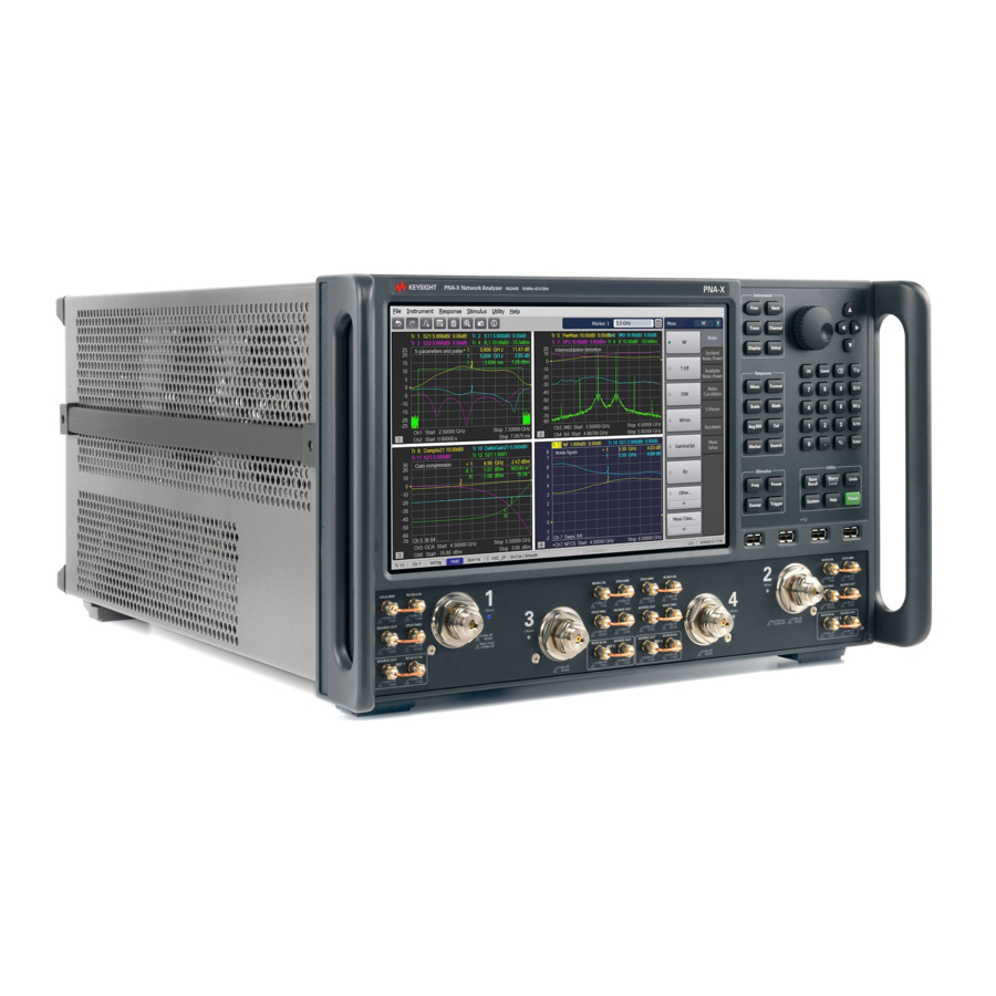
Models Covered in this Guide
| PNA-X Pro | PNA-X | PNA | PNA-L |
| NA5202A | N5241B | N5221B | N5231B |
| NA5204A | N5242B | N5222B | N5232B |
| NA5205A | N5244B | N5224B | N5234B |
| N5245B | N5225B | N5235B | |
| N5247B | N5227B | N5239B | |
| N5249B | N5222BT | ||
| N5225BT |

The PNA-X Pro is very heavy. Its weight exceeds the limits for standard shipments for any of the major freight handlers - DHL, FedEx, UPS, etc. Shipping the PNA-X Pro requires that it be handled as freight, meaning that it must be secured to a pallet which can be lifted by a forklift. The PNA-X Pro is shipped from Keysight in this configuration. The end-user must retain this pallet and other shipping material for sending the PNA-X Pro to Keysight for its annual calibration or any servicing. The major freight handlers will reject any attempt at shipping the PNA-X Pro without a pallet.
Safety Symbols
The following safety symbols are used throughout this manual. Familiarize yourself with each of the symbols and its meaning before operating this instrument.

Denotes a hazard. It calls attention to a procedure that, if not correctly performed or adhered to, would result in damage to or destruction of the product. Do not proceed beyond a caution note until the indicated conditions are fully understood and met.
Denotes a hazard. It calls attention to a procedure which, if not correctly performed or adhered to, could result in injury or loss of life. Do not proceed beyond a warning note until the indicated conditions are fully understood and met.
Documentation Map
The online Help file is embedded in the analyzer, offering quick reference to programming and user documentation. PNA Help is available in English only.
The Installation and Quick Start Guide helps to quickly familiarize yourself with the analyzer. Procedures are provided for installing, configuring, and verifying the operation of the analyzer.
Operating Precautions
Most causes of instrument failure can be avoided if you will apply the information in this section. PLEASE READ!
Preventing Electrostatic Discharge Damage
Protection against electrostatic discharge (ESD) is essential while removing assemblies from or connecting cables and assemblies (DUT) to the network analyzer. Static electricity can build up on your body and can easily damage sensitive internal circuit elements when discharged. Static discharges too small to be felt can cause permanent damage. To prevent damage to the instrument:
- always have a grounded, conductive table mat in front of your test equipment.
- always wear a grounded wrist strap, connected to a grounded conductive table mat, having a 1 MΩ resistor in series with it, when handling components and assemblies or when making connections.
- always wear a heel strap when working in an area with a conductive floor. If you are uncertain about the conductivity of your floor, wear a heel strap.
- always ground yourself before you clean, inspect, or make a connection to a static-sensitive device or test port. You can, for example, grasp the grounded outer shell of the test port or cable connector briefly.
- always ground the center conductor of a test cable and DUT before making a connection to the analyzer test port or other static-sensitive device. This can be done as follows:
- Connect a short (from your calibration kit) to one end of the cable and DUT to short the center conductor to the outer conductor.
- While wearing a grounded wrist strap, grasp the outer shell of the cable and DUT connector.
- Connect the other end of the cable to the test port.
- Remove the short from the cable.

The following table lists Keysight part numbers for ESD protection devices. To order, refer to "Contacting Keysight".
| Description | Keysight Part Number |
| Grounding wrist strap | 9300-1367 |
| 5-ft grounding cord for wrist strap | 9300-0980 |
| 2 x 4 ft conductive table mat and 15-ft grounding wire | 9300-0797 |
Preventing Electrical Overstress Damage
NOTE
The instrument can operate with mains supply voltage fluctuations up to ± 10% of the nominal voltage.
Excessive RF power or voltage applied to the ports and connectors on the front panel will damage the analyzer. Each port and front-panel connector has a label (see photo below) that shows damage levels. These levels must not be exceeded. Damage levels are also listed in the Specifications section of the analyzer's Help system.

There are two ways to protect the PNA input ports from high RF power:
- Use power limiters at the ports. Information on limiters can be found at: www.keysight.com/find/mta.
- Apply the recommendations in PNA Application Note 1408-10, "Recommendations for Testing High-Power Amplifiers," found at: https://www.keysight.com/us/en/assets/9921-01766/user-manuals/Users-Guide-A-Series-N991xA-2xA-3xA-5xA-6xA-Unabridged.pdf (5989-1349EN).
Preventing Test Port Connector Damage
Proper connector care and connection techniques are critical for accurate and repeatable measurements. The following table contains for tips on connector care.
For more information on the proper use and maintenance of connectors, see https://rfmw.em.keysight.com/wireless/helpfiles/N52xxB/Tutorials/Connector_Care.htm.
Observe Proper Shutdown Procedures
To turn the PNA OFF, BRIEFLY press the front panel On/Standby switch. The PNA will then begin to shutdown.
The On/Standby indicator changes from green to yellow when power is Off.
Do NOT Modify or Reconfigure the Operating System
The Microsoft Windows operating system has been modified and optimized by Keysight to improve the performance of the PNA.
- Do NOT install a standard version of the Windows operating system on the PNA.
- Do NOT change advanced performance settings or group policies.
- Do NOT add or delete any SSD partitions on the PNA.
- Do NOT delete the Keysight user account unless in a secured environment.
- Do NOT modify any of the Keysight software registry entries.
- DO NOT disconnect mains power to shutdown the PNA, except when absolutely necessary. Doing so can damage the power supply, solid state drive, or other internal assemblies.
Install Antivirus and Firewall Protection
No antivirus software is shipped with the analyzer. It is recommended that you install antivirus software if your analyzer is connected to the LAN. Check with your IT department to see what they recommend.
The analyzer is shipped with the Windows firewall and Windows Defender enabled.
Do not modify the default network settings as this may cause problems with the operating system of the analyzer.
To adjust Windows Defender settings, log in as administrator (refer to "User Accounts" in the PNA Online Help, https://rfmw.em.keysight.com/wireless/helpfiles/N52xxB/help.htm) and minimize the PNA-Series Application and click on the Start button and type: defender
Then click on Windows Defender from the Best match column.
Install Spyware Protection
There is no anti-spyware software installed on the instrument. This should not be a problem if you do not use the instrument for a lot of internet browsing. Having spyware in the instrument could have an impact on the instrument performance.
Firmware Downgrades
STOP!
Do not downgrade the firmware on your PNA below the version that was installed at the factory, because it will render the hardware inoperable
Do not downgrade the PNA firmware below the version that was installed by the factory. Many components require a minimum firmware revision to run properly. Downgrading below this version will render the hardware inoperable. Reversing this firmware downgrade may not recover the hardware operation.
For example, the Direct Digital Synthesizers require firmware A.14.xx and above. Downgrading to older firmware will permanently disable the hardware.
Installing Your Analyzer
Overview of the Installation Procedure
Safety of any system incorporating the equipment is the responsibility of the assembler of the system.
NOTE
Only Keysight approved accessories shall be used.
NOTE
This procedure requires an open or short calibration standard that mates with the front panel test ports. The open or short calibration standard is NOT included with the PNA.
- Check the Shipment
- Unpack the contents of the shipping container. Keep the packaging material in case the analyzer needs to be returned to the factory.
![]()
For products with a weight > 50 kg refer to your company's Health and Safety department before lifting and moving.
![]()
More than one person is required to safely lift or carry this instrument. Alternately a mechanical lift can be used to eliminate the risk of personal injury.
NOTE
The PNA is shipped with ESD-safe protective end caps on the test ports, impact covers, and metal covers for the front-panel jumpers. Save these items for reuse to ensure shipment safety of the PNA. - Carefully inspect the analyzer to make sure that it was not damaged during shipment. If damaged, refer to "Contacting Keysight".
- Use the Contents List in the shipping container to verify the completeness of your shipment. If not complete, refer to "Contacting Keysight".
- Unpack the contents of the shipping container. Keep the packaging material in case the analyzer needs to be returned to the factory.
- Meet Requirements
Before installing the PNA on a bench top or in an equipment rack, first make sure that the electrical and environmental requirements of the location are met.
![]()
- This instrument has an autoranging line voltage input. Before switching on the instrument, be sure the supply voltage is within the specified range and voltage fluctuations do not exceed 10 percent of the nominal supply voltage.
- Condensing humidity operating conditions are not allowed. Refer to "Environmental Information".
- The instruments can operate with mains supply voltage fluctuations up to ± 10% of the nominal voltage.
- Ensure the available AC power source meets the following requirements:
Model Mains Supply Voltage Frequency Power N52xxB models: 100-120 VAC 50/60/400 Hz 575W MAX 200-240 VAC 50 /60 Hz 575W MAX NA520xA models: 100-120 VAC 50/60/400 Hz 1200Wa 200-240 VAC 50 /60 Hz 1200Wa - The power rating for these models requires that the instrument be plugged into a dedicated circuit.
- Verify that the AC power cable is not damaged, and that the power-source outlet provides a protective earth contact.
![]()
Use Keysight supplied power cord or one with same or better electrical rating.
![]()
Always use the three-prong AC power cord supplied with this product. Failure to ensure adequate earth grounding by not using this cord may cause personal injury or product damage.

- Ensure the operating environment meets the requirements found in "Safety, Regulatory, and Environmental Information".
NOTE
Some analyzer performance parameters are specified for 25°C. Refer to the Help system in the analyzer for the complete specifications.
- Ensure the available AC power source meets the following requirements:
- Install the Analyzer
![]()
Please review all safety information located in "Safety, Regulatory, and Environmental Information", before proceeding with installing and using the analyzer
The analyzer can be installed on a bench top or in an equipment rack. When installing an analyzer equipped with handles in an equipment rack, use Option 1CP. When installing an analyzer not equipped with handles in an equipment rack, use Option 1CM.
In all installations, consider the following ventilation requirements when deciding where to set up your analyzer.
To Install in an Equipment Rack
(Option 1CP - Rack Mounting For Instruments Equipped With Handles)
(Option 1CM - Rack Mounting For Instruments Not Equipped With Handles)
When you install the analyzer in an equipment rack, you must install rails in the rack to support the weight of the analyzer. Attach either the Option 1CP or Option 1CM rack mount flanges to the analyzer. Secure the analyzer to the equipment rack. Replace the analyzer bottom plastic feet with the hole plugs provided.
For installation, follow the instructions provided with the rack mount kit and the rail kit. - Connect the Accessories
USB devices can be connected to any available USB port. All ports comply with a minimum of USB 2.0 specifications. The PNA will recognize the USB device when it is connected and run the appropriate software driver to make the device operate correctly. However, there is a limit to the amount of current that the PNA USB ports can provide. See PNA Help - "USB port specifications" (index entry) for more information.
When starting the PNA, do not have any USB devices connected other than a mouse and keyboard. The current draw from other accessories can impact the initial boot-up sequence.
NOTE
Consider ergonomics when locating the mouse and keyboard.
NOTE
Do NOT connect an ECal module to the USB until after the PNA is started. Once the PNA is started, press the front panel Help button to learn about 'Connecting an ECal module for the first time'. - Ferrite Cores
CISPR 11 is an international regulation that specifies the maximum level of frequency emissions that can originate from an electronic device. The regulation is designed to minimize the interference that one electronic device may have with another.
Frequency emissions can occur when cables are connected to an electronic device. To minimize this, try to use high-quality cables with built-in molded ferrite cores, with the core closest to the PNA. If cables with built-in cores cannot be found, use clamp-on ferrite cores. It is especially important to use these cores on USB cables and LAN cables.
The core should snap closed to grip the cable firmly, but without damaging the cable. Attach the core to the cable as close as possible to the PNA connector end. Cable ties help ensure that the ferrite cores remain in place

- Start Up the Analyzer
![]()
Install the instrument so that the detachable power cord is readily identifiable and is easily reached by the operator. The detachable power cord is the instrument disconnecting device. It disconnects the mains circuits from the mains supply before other parts of the instrument. The front panel switch is only a ON/Standby switch and is not a LINE (OFF) switch.- Connect the AC power cable.
- Turn the analyzer on by pressing the front panel On/Standby switch.


Do NOT press keys on the front panel, rotate the RPG knob, or connect a USB device during boot up of Windows or of the PNA application program. Doing so may lead to a front panel lockup state.

NOTE
This product contains a Windows operating system. The Network Analyzer application is supported and qualified only with the version of Windows that was installed when shipped.
Windows 10 Operating Systems
Windows 10 comes with a display technology called ClearType. This makes displayed text much easier to read on the PNA. The only drawback comes with viewing the display from the bottom. The colors of some small display elements will appear to shift when the viewer's eyes are more than 30 degrees below perpendicular. If necessary, ClearType can be disabled. On the PNA desktop, click Start, then Control Panel then Appearance and Personalization, then Display, then Adjust ClearType Text.
- Perform Administrative Tasks
We recommend that you consider performing the following administrative tasks shortly after powering up the analyzer for the first time.- Set up the administrator password only if required for your location. The PNA already has a default password.
- Set the time, date, and time zone (if needed).
NOTE
Do NOT create additional User Accounts until you have read the PNA Help file topic: "PNA User Accounts and Passwords" which states why and how this should be done.
Procedures for the above tasks are in the Help system in the analyzer. To view these procedures: - On the analyzer's front panel, press the Help button. Or, on the PNA display, click Help > Network Analyzer Help.
Click Quick Start in PNA Help.
Click Perform Administrative Tasks.
Click the task you wish to perform.
- Run the Operator's Check
The operator's check should be performed when you first receive your analyzer, and any time you wish to have confidence that the analyzer is working properly. The operator's check does not verify performance to specifications, but should give you a high degree of confidence that the instrument is performing properly. The only equipment required is an open or short calibration standard that mates with the front panel test ports. The open or short calibration standard is NOT included with the PNA.
NOTE
If a "Log Error" is displayed during the verification stating that a 'filename.csv' is already open and in use, verify that you only have a single verification window open. This can be verified by mousing over the verification icon on the toolbar as the bottom of the display. If there are two verification windows open, close the window on the right most side, which is the most recently opened window. And, resume the verification.- Press System, then [Service] softkey, then [Verification] softkey, then [Operator's Check]. Follow the prompts.
- For assistance, use the Help button displayed on the screen of the Operator's Check.
- Turn Off the Analyzer
To turn the PNA OFF, BRIEFLY press the front panel On/Standby switch. The PNA will then begin to shutdown
Shutdown
The On/Standby indicator changes from green to yellow when power is Off.
The current instrument state is NOT saved to the PNA solid state drive.
When the PNA is powered ON, a full system boot-up is performed and the PNA powers-up in the Preset settings.
NOTE
Repeatedly doing either of the following two actions may cause damage to the PNA solid state drive.- Only in an emergency should the power cord be removed from the PNA without first being put in Shutdown mode.
- If the PNA is locked and you cannot operate the mouse or keypad, turn OFF the PNA by pressing and holding the power button for at least four seconds.
Windows 10 Operating System
The N52xxB and NA520xA models have Microsoft Windows installed at the factory.
Getting Help with Your Analyzer
Help System
Use on-line Help to quickly reference programming and user documentation. On-line Help is only available in English.
We recommend that you begin by accessing Help and reading the topics in the Quick Start section. To access this information:
- On the analyzer's front panel, press the Help button. Or, on the PNA display, click Help, then Network Analyzer Help.
- Click Quick Start in PNA Help.
PNA on the Internet
Keysight maintains a large collection of resources for help with the PNA Family of Network Analyzers. You can find all PNA documentation and other resources by going to https://www.keysight.com/, entering your PNA model number, and clicking on Technical Support.
You can also post your questions for the measurement experts at the Keysight Network Analyzer Forum: http://www.keysight.com/owc_discussions.
Contacting Keysight
Assistance with test and measurements needs and information on finding a local Keysight office are available on the Web at: www.keysight/find/assist. If you do not have access to the Internet, please contact your Keysight field engineer.
NOTE
In any correspondence or telephone conversation, refer to the Keysight product by its model number and full serial number. With this information, the Keysight representative can determine whether your product is still within its warranty period.
Safety, Regulatory, and Environmental Information
Maintenance
To remove dirt or dust from the external case of the network analyzer, clean the case using a dry or slightly-dampened cloth only.

To prevent electrical shock, disconnect analyzer from mains before cleaning. Use a dry cloth or one slightly dampened with water to clean the external case parts. Do not attempt to clean internally.
Shipment for Service
Contact Keysight Technologies for instructions on where to ship the analyzer for service. Refer to "Getting Assistance from Keysight".
Ship the analyzer using the original or comparable packaging, impact covers, and antistatic materials. Shipping the analyzer in anything other than the original or comparable packaging, impact covers, and antistatic materials may result in non-warranted damage.
Safety Symbols
The following safety symbols are used throughout this manual. Familiarize yourself with each of the symbols and its meaning before operating this instrument.
Denotes a hazard. It calls attention to a procedure which, if not correctly performed or adhered to, could result in injury or loss of life. Do not proceed beyond a warning note until the indicated conditions are fully understood and met
Denotes a hazard. It calls attention to a procedure that, if not correctly performed or adhered to, would result in damage to or destruction of the product. Do not proceed beyond a caution note until the indicated conditions are fully understood and met.
General Safety Considerations
Safety Earth Ground
This is a Safety Protection Class I Product (provided with a protective earthing ground incorporated in the power cord). The mains plug shall only be inserted in a socket outlet provided with a protective earth contact. Any interruption of the protective conductor inside or outside of the product is likely to make the product dangerous. Intentional interruption is prohibited.
The Mains wiring and connectors shall be compatible with the connector used in the premise electrical system. Failure to ensure adequate earth grounding by not using the correct components may cause product damage and serious injury.
Before Applying Power
If this product is not used as specified, the protection provided by the equipment could be impaired. This product must be used in a normal condition (in which all means for protection are intact) only.
The input terminals for this product are classified as Measurement Category None (No transients).
High power consuming equipment. Carefully read the safety information provided with your product. Verify the installation conditions are suitable to safely provide power to your equipment.
DO NOT use a power strip that is not suitable for the installation. These devices may not be sufficiently rated to carry the required current and may become a safety hazard.
DO NOT use extension cords to power your equipment.
DO NOT use any converters or adapters.

DO NOT use an outlet if the power cord makes a loose connection.

DO NOT allow plug to bend down or become loose.

The AC Voltage source (outlet) must be in proper working order and provide a secure electrical connection.
Do not use the outlet if the power cord makes a loose connection or if the power cord plug does not match the outlet. Do not use the outlet if it is damaged or if the voltage is outside the required range.
If an instrument handle is damaged, you should replace it immediately. Damaged handles can break while you are moving or lifting the instrument and cause personal injury or damage to the instrument.
This product is designed for use in Installation Category II and Pollution Degree 2 per IEC standards.
Ventilation Requirements: When installing the instrument(s) into a cabinet consideration shall be given to the convection flow into and out of the cabinet. Consideration shall also be given to the individual instruments to avoid having the heated discharge of one instrument, now becoming the cooling intake air for another instrument.
Another area of concern is verification that the maximum ambient operating temperature of the instrument(s) is not exceeded by cabinet installation. Keysight recommends forced air convection whenever an instrument(s) are installed in a cabinet and further recommends that the maximum operating temperature of the cabinet be reduced 10°C from the lowest, of the maximum operating temperature of a single instrument.
Do not obstruct openings. Allow a minimum 70 mm clearance for proper cooling.
If there are any concerns or special requirements a Keysight Field Engineer should be consulted to assure instrument(s) temperature compliance and performance.
The measuring terminals on this instrument are designed to be used with external signals described in Measurement Category None, but NOT with external signals described in Categories II, III, and IV. The input of this instrument cannot be connected to the mains.
Servicing
No operator serviceable parts inside. Servicing should only be done by qualified service personnel. To prevent electrical shock or instrument damage, the operator should never remove covers. Qualified service personnel must remain mindful of these items:
- The power cord is connected to internal capacitors that may remain live for 5 seconds after disconnecting the plug from its power supply.
- The opening of covers or removal of parts may expose dangerous voltages. Disconnect the instrument from all voltage sources while it is being opened.
- All internal assemblies are capable of rendering an electrical shock or burn when power is applied.
- Some adjustment procedures described in this document need be performed with power supplied to the product while protective covers are removed. Energy available at many points may, if contacted, result in personal injury or instrument damage. Heed all warnings given in the adjustment procedures.
- Danger of explosion if battery is incorrectly replaced. Replace only with the same or equivalent type recommended. Discard used batteries according to local ordinances and/or manufacturer's instructions.
Regulatory Information
This section contains information that is required by various government regulatory agencies.
NOTE
The table below lists the definitions of markings that may be on or with the product. Familiarize yourself with each marking and its meaning before operating the instrument.
Instructions for Use
This product has been designed and tested in accordance with accepted industry standards, and has been supplied in a safe condition. The documentation contains information and warnings that must be followed by the user to ensure safe operation and to maintain the product in a safe condition.
Install the instrument so that the detachable power cord is readily identifiable and is easily reached by the operator.
The detachable power cord is the instrument disconnecting device. It disconnects the mains circuits from the mains supply before other parts of the instrument. The front panel switch is only a standby and ON switch and is not a LINE switch (disconnecting device).
The table below lists the definitions of markings that may be on or with the product. Familiarize yourself with each marking and its meaning before operating the instrument
Table 1
 | This symbol marks the standby position of the power line switch. |
 | This symbol marks the ON position of the power line switch. |
 | This symbol marks the OFF position of the power line switch. |
 | This symbol indicates that the input power required is AC. |
 | This symbol indicates DC voltage |
 | This symbol indicates a three-phase alternating current. |
 | This symbol indicates Frame or chassis Terminal. |
 | The instruction documentation symbol. The product is marked with this symbol when it is necessary for the user to refer to the instruction in the documentation. |
 | This symbol indicate the presence of a Laser device. |
 | This symbol indicates the surface can be hot. |
 | This symbol indicated the product is sensitive to electrostatic discharge. |
 | This symbol identifies the Protective Conductor terminal. |
 | This symbol indicates the equipment is protected throughout by double or reinforced insulation. |
 | This symbol indicated the mass of the equipment. |
 | The CE mark is a registered trademark of the European Community (if accompanied by a year, it is the year when the design was proven). It indicates that the product complies with all the relevant directives. |
 | The UK conformity mark is a UK government owned mark. Products showing this mark comply with all applicable UK regulations. |
 | The Keysight email address is required by EU directives applicable to our product. |
 | The CSA mark is a registered trademark of the CSA International. |
 | For products with a weight > 50kg., refer to your company Health and Safety department before lifting and moving. |
| CAN ICES/NMB-001(A) | Canada EMC label. Interference-Causing Equipment Standard for industrial, scientific and medical (ISM) equipment. Matériel industriel, scientifique et médical (ISM). |
 | CE/ICES/ISM label. (Old mark for reference only.) This is a space saver label that combines three markings - CE with CAN ICES and ISM (see above) and ISM (see below). |
 | This is a space saver label that combines three markings - CE with CAN ICES and ISM (see above) and ISM (see below). |
 | The RCM mark is a registered trademark of the Australian Communications and Media Authority. |
 | This is a space saver label that combines two markings - CAN ICES and ISM. |
 | This is a symbol of an Industrial Scientific and Medical Group 1 Class A product (CISPR 11, Clause 5). |
 | South Korean Certification (KC) mark. It includes the marking's identifier code. |
 | The crossed-out wheeled bin symbol indicates that separate collection for waste electric and electronic equipment (WEEE) is required, as obligated by the EU DIRECTIVE and other National legislation. Please refer to https://about.keysight.com/en/companyinfo/environment/takeback.shtml to understand your trade-in options with Keysight, in addition to product takeback instructions. |
 | China Restricted Substance Product Label. The EPUP (environmental protection use period) number in the center indicates the time period during which no hazardous or toxic substances or elements are expected to leak or deteriorate during normal use and generally reflects the expected useful life of the product. |
 | Universal recycling symbol. This symbol indicates compliance with the China standard GB 18455-2001 as required by the China RoHS regulations for paper/fiberboard packaging. |
 | This mark indicates product has been designed to meet the requirements of "IP x y", where "x" is the solid particle protection and "y" is the liquid ingress protection. |
Safety Notices
A CAUTION notice denotes a hazard. It calls attention to an operating procedure, practice, or the like that, if not correctly performed or adhered to, could result in damage to the product or loss of important data. Do not proceed beyond a CAUTION notice until the indicated conditions are fully understood and met.
A WARNING notice denotes a hazard. It calls attention to an operating procedure, practice, or the like that, if not correctly performed or adhered to, could result in personal injury or death. Do not proceed beyond a WARNING notice until the indicated conditions are fully understood and met.
Where to Find the Latest Information
Documentation is updated periodically. For the latest information about this product, including instrument software upgrades, application information, and product information, browse to the following URL:
https://www.keysight.com/find/pna
Information on preventing instrument damage can be found at:
http://keysight.com/find/PreventingInstrumentRepair
Is your product software up-to-date?
Periodically, Keysight releases software updates to fix known defects and incorporate product enhancements. To search for software updates for your product, go to the Keysight Technical Support website at:
http://www.keysight.com/find/techsupport
Product and Solution Cybersecurity
Keysight complies with multinational regulations for the cybersecurity of its own products and is committed to providing information to assist you in protecting your products and solutions from external cyber threats. For more information, see:
https://www.keysight.com/us/en/about/quality-and-security/security/product-and-solution-cyber-security.html
Keysight also recommends that you secure your IT environments using appropriate third-party tools. For instruments that run the Microsoft Windows operating system, Keysight concurs with Microsoft's recommendations for ensuring that the instrument is protected:
- Get the latest critical Windows updates
- For network-connected instruments, use an Internet firewall (in Keysight instruments, Windows Firewall is enabled by default)
- For network-connected instruments, use up-to-date antivirus and anti-spyware software
Responsible Disclosure Program
Keysight recommends that security researchers share the details of any suspected vulnerabilities across any asset owned, controlled, or operated by Keysight (or that would reasonably impact the security of Keysight and our users) using this form:
https://www.keysight.com/us/en/contact/responsible-disclosure-program.html
Report a Product Cybersecurity Issue
If you discover a cybersecurity issue that you suspect may involve Keysight's proprietary software, or third-party software supplied by Keysight as part of a product, or that may affect the operation of Keysight products, we encourage you to report it to us using this form:
https://www.keysight.com/us/en/about/quality-and-security/security/product-and-solution-cyber-security/reporta-product-cybersecurity-issue
Getting Assistance from Keysight
Installing this upgrade kit requires special skills and experience. If you think you may not be qualified to do the work, or need advice, contact Keysight.
Contacting Keysight
NOTE
For optimum service, before contacting Keysight, it is important to sign up for Keysight Care to improve turnaround time and committed service levels on both application support as well as post-sales support.
Learn more http://www.keysight.com/find/keysightcare.portal.
Assistance with test and measurements needs and information on finding a local Keysight office are available on the Web at: http://www.keysight.com/find/assist
If you do not have access to the Internet, please contact your Keysight field engineer.
In any correspondence or telephone conversation, refer to the Keysight product by its model number and full serial number. With this information, the Keysight representative can determine whether your product is still within its warranty period.
NOTE
To contact Keysight for sales and technical support, refer to support links on the following Keysight websites: http://www.keysight.com/find (product specific information and support, software and documentation updates) http://www.keysight.com/find/assist (worldwide contact information for repair and service).
www.keysight.com
Documents / Resources
References
Download manual
Here you can download full pdf version of manual, it may contain additional safety instructions, warranty information, FCC rules, etc.
Download Keysight PNA Series, PNA-X Pro, PNA-X, PNA-L Manual
Advertisement


Need help?
Do you have a question about the PNA Series and is the answer not in the manual?
Questions and answers