Table of Contents
Advertisement
Quick Links
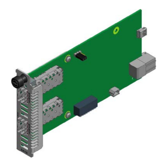
C4110-4848
Install Guide
10 Gbps Fiber-to-Fiber Converter
• DMI (Diagnostic Monitoring Interface)
• For use in ION Chassis
• Manageable when installed in a managed ION Chassis
• Supports various physical media types
• Fiber repeater, performs 3R signal regeneration
• Link Pass Through (LPT)
• No packet size limitation
Contents
Introduction .................................................................................................................................................. 3
Models .......................................................................................................................................................... 3
Accessories (ordered separately) .................................................................................................................. 4
Document Overview ..................................................................................................................................... 4
Related Manuals and Online Help ................................................................................................................ 4
Application Examples .................................................................................................................................... 5
Network Scenarios .................................................................................................................................... 6
Pre-Installation .............................................................................................................................................. 7
Safety ........................................................................................................................................................ 7
Unpacking ................................................................................................................................................. 7
Ship Kit Contents ...................................................................................................................................... 7
DIP Switch (SW1) and Jumper (J9) ............................................................................................................ 8
Installation and Setup ................................................................................................................................. 10
General ................................................................................................................................................... 10
Install the C4110 in the ION Chassis ....................................................................................................... 10
Installing SFP/SFP+ Devices .................................................................................................................... 11
Cabling .................................................................................................................................................... 12
Install Fiber Cable ................................................................................................................................... 13
Focal Point™ Installation ........................................................................................................................ 13
IONMM Installation ................................................................................................................................ 13
Operation .................................................................................................................................................... 14
Power and Fiber Status LEDs .................................................................................................................. 14
Accessing the C4110 ............................................................................................................................... 15
Product Features .................................................................................................................................... 24
Technical Specifications .............................................................................................................................. 25
Defaults ................................................................................................................................................... 25
Cable Specifications ................................................................................................................................ 26
Cable Types ............................................................................................................................................. 26
Messages ................................................................................................................................................ 28
Troubleshooting .......................................................................................................................................... 29
Contact Us ................................................................................................................................................... 30
Compliance Information ............................................................................................................................. 30
33572 Rev. B
https://www.transition.com/
Page 1 of 33
Advertisement
Table of Contents

Related Manuals for Transition Networks C4110


Summary of Contents for Transition Networks C4110
-
Page 1: Table Of Contents
Ship Kit Contents ............................7 DIP Switch (SW1) and Jumper (J9) ......................8 Installation and Setup ..........................10 General ..............................10 Install the C4110 in the ION Chassis ....................... 10 Installing SFP/SFP+ Devices ........................11 Cabling ..............................12 Install Fiber Cable ........................... 13 Focal Point™... - Page 2 Transition Networks C4110 Install Guide Declaration of Conformity ........................30 FCC Regulations ............................31 Canadian Regulations ..........................31 European Regulations ..........................31 Electrical Safety Warnings ........................32 Safety Instructions for Rack Mount Installations ................... 33 Record of Revisions ............................. 33 33572 Rev.
-
Page 3: Introduction
The S4110 is used as a stand-alone device or as a remote device when linked back to a managed chassis card. The C4110 SIC card can be managed by ION Web, ION CLI, or Focal Point 3.0. The S4110 can not be remotely managed. -
Page 4: Accessories (Ordered Separately)
A printed documentation card is shipped with each x4110 device. A substantial set of technical documents, white papers, case studies, etc. are available on the Transition Networks web site at https://www.transition.com. Note that this manual provides links to third party web sites for which Transition Networks is not responsible. -
Page 5: Application Examples
Transition Networks C4110 Install Guide Application Examples The figures below show switch-to-switch and switch-to-server appliaction examples. Figure 1: 10Gig Switch to Switch Figure 2: 10Gig Switch to Server 33572 Rev. B https://www.transition.com/ Page 5 of 33... -
Page 6: Network Scenarios
C4110 Install Guide Network Scenarios The C4110 provides up to 10Gig fiber-to-fiber port repeating and performs 3R (re-amplify, reshape) signal regeneration. The figures below show how x4110 devices can be used in pairs (scenarios A,B,C below) or used as single repeater in a customer network (scenarios D & E below); It can also interconnect with an x4110-1048 (scenario F). -
Page 7: Pre-Installation
Place the C4110 and related materials in the desired install location. 4. Save the C4110 shipping carton and packing materials for future use. Ship Kit Contents The C4110 is shipped with some standard and some optional components. Make sure you have received the following standard items: ... -
Page 8: Dip Switch (Sw1) And Jumper (J9)
Use the CLI command “ show card info ” to show the current Config mode setting (hardware or software). From the web GUI, navigate to the ION Stack > Chassis > C4110 menu path and check the MAIN tab’s System Configuration section > Configuration Mode field setting (i.e., hardware or software). - Page 9 DIP Switch SW1 (Function Settings in Hardware Mode) The 8-position DIP switch labeled SW1 is on the bottom edge of the C4110 PCB. The factory default setting is SW1 – 4 in the Down position (all Down). SW5 - 8 settings are not used (‘do not care’).
-
Page 10: Installation And Setup
1. Locate an empty slot in the ION System chassis. If necessary, remove a chassis slot cover from the ION Chassis (keep the slot cover and screw). 2. Grasp the edges of the C4110 by its front panel, align the card with the upper and lower slot guides, and carefully insert the C4110 into the slot. -
Page 11: Installing Sfp/Sfp+ Devices
The C4110 has two ports. The locations of PORT1 and PORT 2 (SFP/SFP+) are shown below. Figure 6: Port Locations Installing SFP/SFP+ Devices The C4110 lets you install SFP/SFP+ devices of choice to make a fiber connection. The C4110 has two SFP/SFP+ ports. Figure 7: SFP/SFP+ Installation Note: The S4100 is an “any rate to same rate”... -
Page 12: Cabling
SFP information. Cabling The C4110 can be used in telecom and enterprise applications where 1Gig to 10Gig links require fiber extension or where 1Gig to 10Gig links require an interface between two fiber networks. It performs 3R (re-amplify, re-shape, and re-time) signal regeneration. -
Page 13: Install Fiber Cable
“Cable Specifications” on page for details. 2. Connect the fiber cable to the 10GE SFP+ fiber port (Port 2 labeled 10GE SFP+) on the C4110 as described: • Connect the male TX cable connector to the female TX connector. • Connect the male RX cable connector to the female RX connector. -
Page 14: Operation
C4110 Install Guide Operation Power and Fiber Status LEDs The status LEDs (labeled PWR and LINK SFP+) are located next to the fiber port (Port 2). Use the status LEDs to monitor C4110 operation in the network. LED Label Meaning Operation Power Green ON for power applied to board. -
Page 15: Accessing The C4110
Accessing the C4110 The C4110 can be accessed through an Ethernet network connection on the IONMM installed in the ION chassis along with the C4110. The network connection can be done via a Telnet session or a Web graphical user interface (GUI). - Page 16 Transition Networks C4110 Install Guide Installing the USB Driver (Windows 8) IMPORTANT The following driver installation instructions are for the Windows 8 operating system only. Installing the USB driver using another operating system is similar, but not necessarily identical to this procedure.
- Page 17 Transition Networks C4110 Install Guide At the Troubleshoot screen choose “Advanced options”. In the Advanced options screen choose “Startup Settings”. A list of Windows Startu Settings displays; click the “Restart” button. Your PC will reboot. 33572 Rev. B https://www.transition.com/ Page 17 of 33...
- Page 18 Transition Networks C4110 Install Guide Your PC will boot into a Startup Settings screen. Select “7) Disable driver signature enforcement”. Your PC will reboot one more time and will not load normally. Plug the USB into the PC and IONMM card and have the USB driver saved locally to the PC.
- Page 19 “Defaults” on page 25). Make note of the original settings for the PC as you will need to reset them after setting the IP configuration for the C4110. Starting a Telnet Session The C4110 can be controlled from a remote management station via a Telnet session over an Ethernet connection.
- Page 20 [c=<0-16>] [s=<0-32>] [l1ap=<1-15>] [l2ap=<1-15>] (l1p=<1-5>|l2p=<1-15>|l3p=<1- 15>|l1d|l2d|l3d) 11. Enter commands to set up the various configurations for the C4110. For web GUI configuration, see the x4110 Web User Guide. For CLI command descriptions see the x4110 CLI Reference manual. Note: If required by your organization’s security policies and procedures, use the CLI command set community write=<xx>...
- Page 21 C4110 Install Guide Starting the Web Interface The C4110 can be controlled and configured from a remote management station via a Web graphical user interface (GUI) over an Ethernet connection. Information is entered into fields on the various screens of the interface. Note: fields that have a grey background can not be modified.
- Page 22 5. Click the plus sign [+] next to Chassis to unfold the chassis devices. 6. Select the appropriate C4110-4848 device. The MAIN screen displays for the selected C4110. 7. You can use the various fields to configure the device and ports. For web GUI configuration, see the x4110 Web User Guide.
- Page 23 The ION sign- in screen displays. Note: The C4110 does not automatically log out upon exit or after a timeout period, which could leave it vulnerable if left unattended. Follow your organizational policy on when to sign out from the ION System via the Web Interface 33572 Rev.
-
Page 24: Product Features
Digital Monitoring Interface (DMI) The Diagnostic Monitoring Interface (DMI) feature allows diagnosing problems within the network. The DMI function displays C4110 diagnostic / maintenance information such as 10Gbps fiber interface characteristics, diagnostic monitoring parameters, and supported fiber media lengths. All DMI events will trigger notification. -
Page 25: Technical Specifications
WARNING: Use of controls, adjustments or the performance of procedures other than those specified herein may result in hazardous radiation exposure. Defaults After you configure the C4110 and insert it into ION chassis, it will start up and run automatically using its defaults. The C4110 initialization default values are shown below. Parameter... -
Page 26: Cable Specifications
Note: the interface standard used is defined by the fiber module used and is transparent to the x4110. All other standards are limiting mode (EDC disabled). Note: the C4110 does not support 10GBase-LX4, 10GBase-CX4, or 10GBase-LRM. 33572 Rev. B https://www.transition.com/... - Page 27 Transition Networks C4110 Install Guide Optical Transport Network (OTN) The Optical Transport Hierarchy (OTH) is a new transport technology for the Optical Transport Network (OTN) developed by the ITU. OTH is based on the network architecture defined in ITU G.872 "Architecture for the Optical Transport Network (OTN)".
-
Page 28: Messages
Transition Networks C4110 Install Guide SONET (Synchronous Optical Transport Network) Synchronous Optical Network, a standard for connecting fiber-optic transmission systems. SONET was proposed by Bellcore in the middle 1980s and is now an ANSI standard. SONET defines interface standards at the physical layer of the OSI seven-layer model. The standard defines a hierarchy of interface rates that allow data streams at different rates to be multiplexed. -
Page 29: Troubleshooting
C4110 Install Guide Troubleshooting If a problem or exception occurs, the C4110 will send related Trap message to the Trap Server to report this event. You can launch the Trap Server in Focal Point 3.0 to capture the Trap message to better understand C4110 status. -
Page 30: Contact Us
Transition Networks C4110 Install Guide Contact Us Technical Support: Technical support is available 24-hours a day US and Canada: 1-800-260-1312 International: 00-1-952-941-7600 Main Office tel: +1.952.941.7600 | toll free: 1.800.526.9267 | fax: 952.941.2322 sales@transition.com techsupport@transition.com customerservice@transition.com Address Transition Networks 10900 Red Circle Drive Minnetonka, MN 55343, U.S.A. -
Page 31: Fcc Regulations
In accordance with European Union Directive 2002/96/EC of the European Parliament and of the Council of 27 January 2003, Transition Networks will accept post usage returns of this product for proper disposal. The contact information for this activity can be found in the 'Contact Us' portion of this document. -
Page 32: Electrical Safety Warnings
Transition Networks C4110 Install Guide Electrical Safety Warnings Electrical Safety IMPORTANT: This equipment must be installed in accordance with safety precautions. Elektrische Sicherheit WICHTIG: Für die Installation dieses Gerätes ist die Einhaltung von Sicherheitsvorkehrungen erforderlich. Elektrisk sikkerhed VIGTIGT: Dette udstyr skal nstallers I overensstemmelse med sikkerhedsadvarslerne. -
Page 33: Safety Instructions For Rack Mount Installations
Notes 3/2/15 Initial release for v 1.2.4. Update for C4110 v1.2.6; add Vendor Specific Info to DMI; add C4110 support in Focal 9/12/16 Point; update driver installation and contact information. Trademark Notice: All trademarks and registered trademarks are the property of their respective owners.
Need help?
Do you have a question about the C4110 and is the answer not in the manual?
Questions and answers