
Subscribe to Our Youtube Channel
Related Manuals for TGB 525


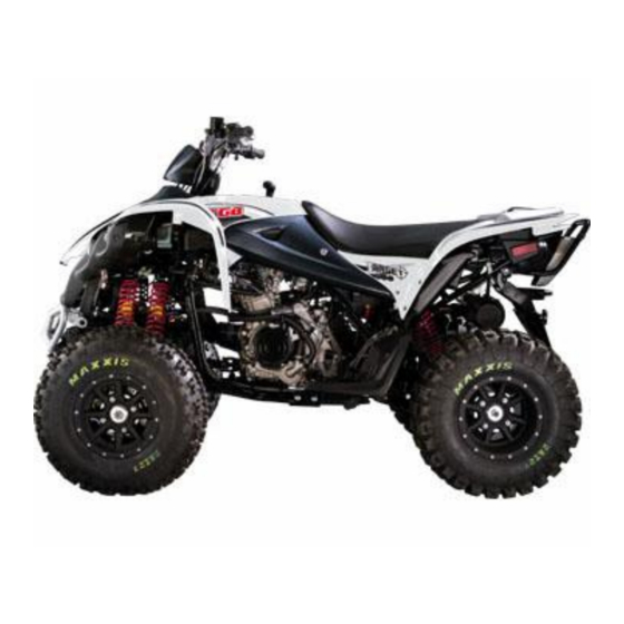
Summary of Contents for TGB 525
- Page 1 TARGET 525 SERVICE MANUAL TAIWAN GOLDEN BEE CO.,LTD. PDF created with pdfFactory Pro trial version www.pdffactory.com...
- Page 2 “Service Procedures”, “Operation Key Points”, and “Inspection Adjustment” so that provides technician with service guidelines. If the style and construction of the ATV 525, are different from that of the photos, pictures shown in this manual, the actual vehicle shall prevail. Specifications are subject to change without notice.
- Page 3 HOW TO USE THIS MANUAL This service manual describes basic information of different system parts and system inspection & service for 525 ATV. In addition, please refer to the manual contents in detailed for the model you serviced in inspection and adjustment.
- Page 4 Homepage CONTENTS Page Content Index 1-1 ~ 1-18 GENERAL INFORMATION 2-1 ~ 2-14 SERVICE MAINTENANCE INFORMATION 3-1 ~ 3-7 LUBRICATION SYSTEM 4-1 ~ 4-12 FUEL SYSTEM 5-1 ~ 5-14 ENGINE REMOVAL 6-1 ~ 6-16 CYLINDER HEAD/VALVE 7-1 ~ 7-8 CYLINDER/PISTON 8-1 ~ 8-14 “V”...
- Page 5 Home page Contents SERIAL NUMBER Frame number Engine number PDF created with pdfFactory Pro trial version www.pdffactory.com...
-
Page 6: Table Of Contents
Homepage Contents 1. GENERAL INFORMATION Symbols and Marks......1-1 Torque Values ........1-10 General Safety ........1-2 Troubles Diagnosis......1-12 Service Precautions ......1-3 Lubrication Points ......1-17 Specifications ........1-9 Symbols and Marks Symbols and marks are used in this manual to indicate what and where the special service are needed, in case supplemental information is procedures needed for these symbols and marks, explanations will be added to the text instead of using the symbols or marks. -
Page 7: General Safety
To this chapter contents 1. GENERAL INFORMATION General Safety Carbon monoxide Battery If you must run your engine, ensure the place is Caution well ventilated. Never run your engine in a closed area. Run your engine in an open area, if you have ‧... -
Page 8: Service Precautions
1. GENERAL INFORMATION Service Precautions ● ● Never bend or twist a control cable to prevent Always use with TGB genuine parts and recommended oils. Using non-designed parts for unsmooth control and premature worn out. TGB ATV may damage the ATV. - Page 9 To this chapter contents 1. GENERAL INFORMATION ● The length of bolts and screws for assemblies, ● Remove residues of the old gasket or sealant cover plates or boxes is different from one another, before reinstallation, grind with a grindstone if be sure they are correctly installed.
- Page 10 To this chapter contents 1. GENERAL INFORMATION ● Lubricate the rotation face with specified ● After service completed, make sure all lubricant on the lubrication points before connection points is secured. assembling. Battery positive (+) cable should be connected firstly. ●...
- Page 11 To this chapter contents 1. GENERAL INFORMATION ● When separating a connector, it locker has to be ● Insert the terminal completely. unlocked firstly. Then, conduct the service Check if the terminal is covered by the boot. operation. Do not let boot open facing up. ●...
- Page 12 To this chapter contents 1. GENERAL INFORMATION ● Do not let the wire harness contact with rotating, ● Protect wires or wire harnesses with electrical moving or vibrating components as routing the tape or tube if they contact a sharp edge or harness.
- Page 13 To this chapter contents 1. GENERAL INFORMATION ● Do not let the wire harness been twisted as ● With sand paper to clean rust on connector installation. pins/terminals if found. And then conduct connection operation later. Clean rust ● Wire harnesses routed along the handlebar should not be pulled too tight or have excessive slack, be rubbed against or interfere with adjacent or surrounding parts in all steering positions.
-
Page 14: Specifications
To this chapter contents 1. GENERAL INFORMATION Specifications MAKER MODEL VSG 500c.c. Overall Length 2080 mm Suspension Front Double Arm System Overall Width 1240 mm Rear Unit Swing Overall Height 1320 mm Front AT23X7-10 Tire Specifications Wheel Base 1290 mm Rear AT22X11-10 Front... -
Page 15: Torque Values
1. GENERAL INFORMATION Torque Values The torque values listed in above table are for more important tighten torque values. Please see standard values for not listed in the table. Standard Torque Values for Reference Type Tighten Torque Type Tighten Torque 5 mm bolt、nut 0.45~0.6kgf-m 5 mm screw... - Page 16 To this chapter contents 1. GENERAL INFORMATION Frame Torque Values Item Q’ty Thread Dia. (mm) Torque Value(kgf-m) Remarks Handlebar upper holder bolt 2.40 Steering shaft nut 5.00 Steering tie-rod nut 5.00 Knuckle nut 5.00 Steering shaft holder bolt 3.40 Tie rod lock nut 3.60 Handlebar under holder nut 4.00...
-
Page 17: Troubles Diagnosis
To this chapter contents 1. GENERAL INFORMATION Troubles Diagnosis A. Engine hard to start or can not be started Check and adjustment Fault condition Probable causes Loosen carburetor drain bolt to check if there is gasoline inside ● No fuel in fuel tank the carburetor ●... - Page 18 To this chapter 1. GENERAL INFORMATION B. Engine run sluggish (Speed does not pick up, lack of power) Check and adjustment Fault condition Probable causes Try gradual acceleration and check engine speed ● Air cleaner clogged ● Poor fuel supply Engine speed can not be Engine speed can be ●...
- Page 19 1. GENERAL INFORMATION C. Engine runs sluggish (especially in low speed and idling) Check and adjustment Fault condition Probable causes Check ignition timing (using ignition lamp) ● Normal Abnormal Incorrect ignition timing (malfunction of CDI or AC alternator) Adjust the air screw of carburetor Good Poor...
- Page 20 To this chapter contents 1. GENERAL INFORMATION E. Clutch, driving and driving pulley FAULT CONDITIONS PROBABLE CAUSES ● Drive belt worn out or deformation ● Ramp plate of movable drive face damaged Engine can be started but ● Driving pulley spring broken motorcycle can not be moved.
- Page 21 1. GENERAL INFORMATION G. Loss power Check and adjustment Fault condition Probable causes Raise wheels off ground and spin by hand ● Brake dragging ● Drive chain too tight Spin freely Abnormal ● Damaged wheel bearing ● Wheel bearing needs lubrication Check tire pressure ●...
-
Page 22: Lubrication Points
To this chapter contents 1. GENERAL INFORMATION Lubrication Points Throttle cable/ Front & Rear brake lever pivot Wheel bearing Speedometer gear 1-17 PDF created with pdfFactory Pro trial version www.pdffactory.com... - Page 23 To this chapter contents 1. GENERAL INFORMATION Note: 1-18 PDF created with pdfFactory Pro trial version www.pdffactory.com...
- Page 24 Home page Contents 2. MAINTENANCE INFORMATION Precautions in Operation ···················· 2-1 Brake System (Disk Brake) ················· 2-8 Periodical Maintenance Schedule ······ 2-2 Brake Light Switch/Starting Inhibitor Switch ··················································· 2-9 Fuel Lines ············································· 2-3 Headlight Beam Distance ···················· 2-10 Acceleration Operation ······················· 2-3 Clutch Disc Wear ·································...
-
Page 25: Periodical Maintenance Schedule
R ~ Replacement T ~ Tighten Have your ATV checked, adjusted, and recorded maintenance data periodically by your TGB Authorized Dealer to maintain the ATV at the optimum condition The above maintenance schedule is established by taking the monthly 1000 kilometers as a reference which ever comes first. -
Page 26: Fuel Lines
To this chapter contents 2. MAINTENANCE INFORMATION Fuel Lines Fuel tank Remove the seat . Loosen 2 screws and 2 bolts Carbureto Remove the tank cover Check all lines, and replace it when they are deterioration, damage or leaking Warning Gasoline is a low ignition material so any kind of fire is strictly prohibited as dealing it. -
Page 27: Valve Clearance
To this chapter contents 2. MAINTENANCE INFORMATION Valve Clearance Caution Checks and adjustment must be performed when the engine temperature is below 35℃. Remove front fender, fuel tank cover and fuel tank. Remove cylinder head cover. Turn camshaft bolt in C.W. direction and let the “T” mark on the camshaft sprocket align with cylinder head mark so that piston is placed at TDC position in compression stroke. -
Page 28: Carburetor Idle Speed Adjustment
To this chapter contents 2. MAINTENANCE INFORMATION Carburetor Idle Speed Adjustment Ignition cable Caution ● Inspection & adjustment for idle speed have to be performed after all parts in engine that needed adjustment have been adjusted. ● Idle speed check and adjustment have to be done after engine is being warm up. -
Page 29: Ignition System
To this chapter contents 2. MAINTENANCE INFORMATION Ignition System Caution ● C.D.I ignition system is set by manufacturer so it can not be adjusted. ● Ignition timing check procedure is for checking whether CDI function is in normal or not. Connect tachometer and ignition light. -
Page 30: Drive Belt
To this chapter contents 2. MAINTENANCE INFORMATION Drive Belt Clamp strips Loosen the 2 clamp strips of clutch cover, and then remove the clutch cover vapor hose. Remove 14 bolts of the clutch cover. 14bolts Check if the belt is crack or worn out. Replace the belt if necessary or in accord with the periodical maintenance schedule to replace it. -
Page 31: Brake System (Disk Brake)
To this chapter contents 2. MAINTENANCE INFORMATION Brake System (Disk Brake) Brake System Hose Make sure the brake hoses for corrosion or leaking oil. Brake Fluid Check brake fluid level in the brake fluid reservoir. If the level is lower than the LOWER limit, add brake fluid to UPPER limit. -
Page 32: Brake Light Switch/Starting Inhibitor
To this chapter contents 2. MAINTENANCE INFORMATION Brake Lining Wear Front brake The indent mark on brake lining is the wear limitation. Replace the brake lining if the wear limit mark Lining closed to the edge of brake disc. Caution ●... -
Page 33: Headlight Beam Distance
To this chapter contents 2. MAINTENANCE INFORMATION Headlight Beam Distance Turn on main switch Headlight beam adjustment. Turn the headlight adjustment screw to adjust headlight beam high. Caution ● To adjust the headlight beam follows related regulations. ● Improper headlight beam adjustment will make in coming driver dazzled or insufficient lighting. -
Page 34: Steering Handle
To this chapter contents 2. MAINTENANCE INFORMATION Steering Handle Caution Check all wires and cables if they are interfered with the rotation of steering handle bar. Lift the front wheel out of ground. Turn handle from right to left alternative and check if turning is smoothly. -
Page 35: Special Tools List
2. MAINTENANCE INFORMATION Special Tools List PARTS NO. : 440649 PARTS NO. : 440650 PARTS NAME : EXTENSION PULLER / PARTS NAME : BUSHING(924739) REMOVER REMOVER PARTS NO. : 440651 PARTS NO. : 440652 PARTS NAME : BEARING(924384) PARTS NAME : BEARING(924384) REMOVER φ15 REMOVER φ20 PARTS NO. - Page 36 2. MAINTENANCE INFORMATION PARTS NO. : 440657 PARTS NO. : 440658 PARTS NAME : CRANK SHAFT HOLDER PARTS NAME : STARTER (924136) HOLDER PARTS NO. : 440659 PARTS NO. : 440660 PARTS NAME : FLYWHEEL REMOVER PARTS NAME : CHAIN WHEEL(924360) &...
- Page 37 2. MAINTENANCE INFORMATION PARTS NO. : 440665 PARTS NO. : 440666 PARTS NAME : IDLER GEAR (924187) PARTS NAME : CLUTCH AND CVT PULLER HOLDER PARTS NO. : 440668 PARTS NO. : 440667 PARTS NAME : CYLINDER HEAD VALVE PARTS NAME : UNIVERSAL JOINT AND SPRING INSTALLER/REMOVER HEAD (924646) INSTALLER...
- Page 38 2. MAINTENANCE INFORMATION PARTS NO. : 552302 PARTS NO. : 552301 PARTS NAME : FINAL DRIVE NUT (N33701) PARTS NAME : OIL SEAL (513350) INSTALLER/REMOVER INSTALLER PARTS NO. : PARTS NO. : PARTS NAME : PARTS NAME : PARTS NO. : PARTS NO.
-
Page 39: Body Cover
13. BODY COVER Mechanism Diagram Speedometer steady Cover Number-plate Bracket Handle bar front cover Front cover ornamental Tail carrier Front body cover Rear lamp ornamental Rear lamp fender Rear body cover Seat Side cover Head lamp fender Foot board First housing 13-1 PDF created with pdfFactory Pro trial version www.pdffactory.com... - Page 40 13. BODY COVER Maintenance Body covers dissemble sequence Seat, battery fixed Fuel cup Feont body cover, front cover ornamental Right / left side cover Right / left foot board Tail carrier, Tail carrier ornamental Rear body cover Bumper, number-plate bracket, first housing Front / rear protector Handle bar front cover Upper bracket assembly...
- Page 41 13. BODY COVER Remove seat. Remove 3 bolts from battery fixed. Remove battery fixeds. Remove 2 wire from battery. Remove battery. Remove 2 bolts from battery fixed.Then,remove cable. Remove 1 couplers from starting motor relay , and then remove starting motor relay. Remove bolts (each side 1 bolts) and 2 couplers Remove fuse box.
- Page 42 13. BODY COVER Remove 1 bolt from battery fixed. Remove 6 bolts from battery fixed. Remove battery fixed. Remove 1 screw and take off shift lever. Remove fuel cap. Remove bolts (each side) from front body cover. Installation Install in reverse order of removal procedures. 13-4 PDF created with pdfFactory Pro trial version www.pdffactory.com...
- Page 43 13. BODY COVER Remove screw and bolt (each side) from front body internal cover. Remove screws (each side) from the part of front body cover,and then remove front body cover. Remove front cover ornamental. Remove 8 screws from right or left side cover. (each side 4 screws) Remove right or left side cover.
- Page 44 13. BODY COVER Remove bolts and screws from right or left foot board.(each side 5 bolts) Remove right or left foot board. Remove screw from tail carrier. Then,remove tail carrier ornamental. Remove 3 bolts from tail carrier,then remove tail carrier. Remove the bolts from rear body cover.
- Page 45 13. BODY COVER Remove the screws and rear lamp couplers under rear body cover. (each side) Remove rear body cover. Remove 4 bolts from frame. (each side 2 bolts) Remove bumper. Remove 4 screws (each side 2 screws) from number-plate bracket. Remove number-plate bracket.
- Page 46 13. BODY COVER Remove 1 bolt from the front part of first housing. Remove bolts from first housing. (each side 1 bolt) Remove right and left head lamp couplers. (each side 2 couplers) Then,remove first housing. Remove 4 bolts from front bumper. (each side 2 bolts) Remove front bumper.
- Page 47 13. BODY COVER Remove 2 bolts from front protector. Remove 2 bolts from front protector,and then remove front protector. Remove bolts from rear protector. (each side 1 bolts) Remove bolts from rear protector (each side 1 bolts),and then remove rear protector Installation Install in reverse order of removal procedures.
- Page 48 13. BODY COVER Remove 2 screws from handle bar front cover. Remove 4 bolts from handle bar front cover. (each side 2 bolts) Remove handle bar front cover. Remove bolts from upper bracket assembly. (each side 2 bolts) Remove speedometer assembly couplers,and then remove upper bracket assembly.
- Page 49 13. BODY COVER Remove 3 bolts form rear frame And 2 bolts from muffler. Remove 4 bolts from cover. Installation Install in reverse order of removal procedures. 13-12 PDF created with pdfFactory Pro trial version www.pdffactory.com...
- Page 50 Home page Contents 14. FRONT BRAKE & FRONT WHEEL Adding Brake Fluid ···························· 14-8 Mechanism Diagram···························14-1 Maintenance Description ···················14-2 Brake fluid replacement / Air-bleed ·· 14-9 Trouble Diagnosis ······························14-3 Front Brake Caliper···························· 14-10 Brake Disk ·········································· 14-11 Front Wheel·········································14-4 Front Brake Master Cylinder ············· 14-11 Front Wheel Hub·································14-4 Disk Brake System Inspection ··········14-7 Mechanism Diagram...
-
Page 51: Maintenance Description
To this chapter contents 14. FRONT BRAKE & FRONT WHEEL Maintenance Description Operational precautions Caution Inhaling asbestos may cause disorders of respiration system or cancer, therefore, never use air hose or dry brush to clean brake parts. Use vacuum cleaner or other authorized tool instead. ●... -
Page 52: Trouble Diagnosis
To this chapter contents 14. FRONT BRAKE & FRONT WHEEL Trouble Diagnosis Soft brake lever Hard steering 1. Air inside the hydraulic system 1. Faulty tire 2. Hydraulic system leaking 2. Insufficient tire pressure 3. Worn master piston 4. Worn brake pad 5. -
Page 53: Front Wheel
To this chapter contents 14. FRONT BRAKE & FRONT WHEEL Front Wheel Removal Raise the front wheels off the ground by placing a jack or other support under the frame. 4 nuts Remove the front wheel nuts, and then remove front wheels. - Page 54 To this chapter contents 14. FRONT BRAKE & FRONT WHEEL Remove 4 socket bolts, and then remove the 4 bolts brake disk from wheel hub. Installation Install the front brake disk to the wheel hub. Install wheel hub and brake disk on to knuckle. Install wheel hub washer and tighten the wheel hub .
-
Page 55: Disk Brake System Inspection
To this chapter contents 14. FRONT BRAKE & FRONT WHEEL Disk Brake System Inspection Inspection By visual examination whether divulges or the damage, with spanner inspection brake tube seam whether becomes less crowded, and the inspection handle bar turn right or turn left, or pressure the cushion, whether besides the pipeline protection department, whether there is interferes, contacts other parts of. -
Page 56: Adding Brake Fluid
To this chapter tents 14. FRONT BRAKE & FRONT WHEEL Adding Brake Fluid Master cylinder Before the brake fluid reservoir is removed, turn the handle so that the brake fluid reservoir becomes horizontal, and then remove the brake fluid reservoir. When maintenance brake system, will be supposed to paint the surface or the rubber parts catches up by the rags. -
Page 57: Brake Fluid Replacement / Air-Bleed
o this chapter contents 14. FRONT BRAKE & FRONT WHEEL Brake fluid replacement / Air-bleed Connect drain hose to air-bleed valve. Open the drain valve on the caliper and operate the brake lever until the old brake fluid is entirely drained out. -
Page 58: Front Brake Caliper
To this chapter contents 14. FRONT BRAKE & FRONT WHEEL Front Brake Caliper Removal Place a container under the brake caliper, and loosen the brake hose bolt and finally remove the brake hose. Caution Do not spill brake fluid on painted surfaces. Remove two caliper bolts and the caliper. -
Page 59: Brake Disk
To this chapter contents 14. FRONT BRAKE & FRONT WHEEL Brake Disk Brake disk Inspection Visually check the brake disk for wear or break. Measure the thickness of the disk at several places. Replace the disk if it has exceeded the service limit. - Page 60 To this chapter contents 14. FRONT BRAKE & FRONT WHEEL Remove the rubber boot. Remove the cir clip. Cir clip Remove the piston and the spring. Rubber boot Clean the master cylinder with recommended Piston brake fluid. Piston cup Spring Master cylinder Master Cylinder Inspection Check the master cylinder for damage or scratch.
- Page 61 To this chapter contents 14. FRONT BRAKE & FRONT WHEEL Master Cylinder Install Install the rubber pad into the groove correctly. Place the master cylinder onto handlebar, and install the bolts. Install the brake lever, and connect leads to brake Brake lever bolt Brake light switch light switch.
- Page 62 Home page Contents 15. STEERING / FRONT SUSPENSION Mechanism Diagram ··························15-1 Steering Tie-Rod ································ 15-6 Operational Precautions ····················15-2 Knuckle ··············································· 15-7 Trouble Diagnosis ······························15-2 Front Cushion ···································· 15-8 Steering Handle ··································15-3 Suspension Arm ································ 15-9 Steering Shaft ·····································15-5 Toe-In ·················································· 15-10 Mechanism Diagram Handle bar assy Connection place...
-
Page 63: Operational Precautions
To this chapter contents 15. STEERING / FRONT SUSPENSION Operational Precautions Torque Values Handlebar upper holder bolt 300~350 kgf-cm Steering shaft holder bolt 300~350 kgf-cm Steering shaft nut 250~350 kgf-cm Steering tie-rod nut 250~350 kgf-cm Knuckle nut kgf-cm Tie rod lock nut 450~550 kgf-cm Suspension arm nut 450~550 kgf-cm... -
Page 64: Steering Handle
To this chapter contents 15. STEERING / FRONT SUSPENSION Steering Handle Removal Remove the handle cover, meter set, handle protect cover and front fender. (Refer to chapter Loosen the socket bolts for the front brake master Master cylinder bolts cylinder, and remove front brake master cylinder. Caution Do not let foreign materials enter into the cylinder. - Page 65 To this chapter contents 15. STEERING / FRONT SUSPENSION Loosen 2 screws, and then remove handle left switch and choke hosing. 2 screws 4 socket bolts Remove switch wire band. Remove handle mounting bolt, and then remove the handle upper holder, handle. Remove 2 nuts to remove handle under holder and meter bracket.
-
Page 66: Steering Shaft
To this chapter contents 15. STEERING / FRONT SUSPENSION Steering Shaft Remove Remove cotter pins, and loosen right and left steering tie-rod nuts. Remove tie-rod. Steering shaft nut Remove the cotter pin steering shaft, and below remove steering shaft nut and washer. Cotter pin Bend out the steering shaft holder nut fixed plate. -
Page 67: Steering Tie-Rod
To this chapter contents 15. STEERING / FRONT SUSPENSION Steering Tie-Rod Remove Remove cotter pin and tie-rod nut from steering shaft side. Remove cotter pin and tie-rod nut from wheel side. Inspection Inspect the tie-rod for damage or bending. Inspect the ball joint rubbers for damage , wear or deterioration. -
Page 68: Knuckle
To this chapter contents 15. STEERING / FRONT SUSPENSION Knuckle Remove Remove front wheel, front brake caliper, front wheel hub and brake disk. Remove cotter pin and tie-rod nut, remove tie rod. Cotter pin Tie-rod Universal holder Remove cotter pin and ball joint nut. Remove upper and under ball joints by ball joint driver. -
Page 69: Front Cushion
To this chapter contents 15. STEERING / FRONT SUSPENSION Front Cushion Nuts Remove Remove front cushion under bolt nuts, and remove the bolts. Nuts Remove front cushion upper bolt nuts, and remove the bolts and cushions. Installation Install in reverse order of removal procedures. Torque value: Front cushion nut 4.6kgf-m... -
Page 70: Suspension Arm
To this chapter contents 15. STEERING / FRONT SUSPENSION Suspension Arm Remove Remove front wheel, wheel hub, and brake caliper, brake disk, tie-rod, knuckle and front cushion. Loosen upper suspension arm nuts, remove swing Suspension arm nuts and bolts arm bolts. Remove upper suspension arm. -
Page 71: Toe-In
To this chapter contents 15. STEERING / FRONT SUSPENSION Toe-In When repair or disassemble steering system parts, must to adjustment the toe-in. Keep the vehicle on level ground and the front wheels facing straight ahead. Mark the centers of the tires to indicate the axle center height. - Page 72 16. REAR BRAKE & REAR WHEEL & REAR CUSHION Brake fluid replacement / Air-bleed ·· 16-9 Mechanism Diagram···························16-1 Maintenance Description ···················16-2 Rear Brake Caliper ····························· 16-10 Trouble Diagnosis ······························16-3 Brake Disk ·········································· 16-11 Rear Wheel ··········································16-4 Rear Brake Master Cylinder ·············· 16-11 Disk Brake System Inspection ··········16-5 Rear Cushion······································...
-
Page 73: Maintenance Description
Brake lever nut 1.00kgf-m Rear cushion mounting bolt Air-bleed valve 0.50kgf-m 4.6kgf-m 9.2kgf-m Swing arm pivot bolt 2.40kgf-m Rear wheel nut Special tools Inner bearing puller: TGB-440645 Rear axle bearing driver (6007LLU): TGB-440640 16-2 PDF created with pdfFactory Pro trial version www.pdffactory.com... -
Page 74: Trouble Diagnosis
To this chapter contents 16. REAR BRAKE & REAR WHEEL & REAR CUSHION Trouble Diagnosis Soft brake lever Vibration or Wobble 1. Air inside the hydraulic system 1. Axle is not tightened well 2. Hydraulic system leaking 2. Bent rim 3. -
Page 75: Rear Wheel
To this chapter contents 16. REAR BRAKE & REAR WHEEL & REAR CUSHION Rear Wheel Removal Raise the rear wheels off the ground by placing a jack or other support under the frame. Remove the rear wheel nuts, and then remove rear wheels. -
Page 76: Disk Brake System Inspection
16. REAR BRAKE & REAR WHEEL & REAR CUSHION Disk Brake System Inspection Inspection By visual examination whether divulges or the damage, with spanner inspection brake tube seam whether becomes less crowded, and the inspection handle bar turn right or turn left, or pressure the cushion, whether besides the pipeline protection department, whether there is interferes, contacts other parts of. -
Page 77: Rear Wheel Axle
16. REAR BRAKE & REAR HEEL & REAR CUSHION Rear Wheel Axle Remove rear wheel housing 4 bolts. Escape rear wheel housing from rear fork assy. Remove tow ball mount 4 bolts (2 bolts each side) 16-6 PDF created with pdfFactory Pro trial version www.pdffactory.com... - Page 78 To this chapter contents 16. REAR BRAKE & REAR WHEEL & REAR CUSHION Remove rear axle housing 4 bolts. Remove rear axle housing Inspection Check bearings on rear wheel axle bearing seat. Rotate each bearing’s inner ring with fingers. Check if bearings can be turned in smooth and silent, and also check if bearing outer ring is mounted on bearing seat.
-
Page 79: Adding Brake Fluid
16. REAR BRAKE & REAR WHEEL & REAR CUSHION Fluid cup Fluid cap Adding Brake Fluid Before the brake fluid reservoir is removed, turn the handle so that the brake fluid reservoir becomes horizontal, and then remove the brake fluid reservoir. When maintenance brake system, will be supposed to paint the surface or the rubber parts catches up by the rags. -
Page 80: Brake Fluid Replacement / Air-Bleed
To this chapter contents 16. REAR BRAKE & REAR WHEEL & REAR CUSHION Air-bleed valve Brake fluid replacement / Air-bleed Connect drain hose to air-bleed valve. Open the drain valve on the caliper and operate the brake lever until the old brake fluid is entirely drained out. -
Page 81: Rear Brake Caliper
To this chapter contents 16. REAR BRAKE & REAR WHEEL & REAR CUSHION Rear Brake Caliper Brake hose bolt Removal Place a container under the brake caliper, and loosen the brake hose bolt and finally remove the brake hose. Caution Do not spill brake fluid on painted surfaces. -
Page 82: Brake Disk
To this chapter contents 16. REAR BRAKE & REAR WHEEL & REAR CUSHION Brake Disk Brake disk Inspection Visually check the brake disk for wear or break. Measure the thickness of the disk at several places. Replace the disk if it has exceeded the service limit. - Page 83 To this chapter contents 16. REAR BRAKE & REAR WHEEL & REAR CUSHION Measure the outer diameter of the piston. Replace the piston if its measured value exceeds allowable limit. Allowable limit: Hand brake 13.954 mm Foot brake 15.850 mm Master Cylinder Assembly Caution ●...
- Page 84 To this chapter contents 16. REAR BRAKE & REAR WHEEL & REAR CUSHION Right footrest side – rear brake master cylinder Install the master cylinder bolts and the master cylinder. Install brake push rod to the brake pedal, and install pin and clip. Caution To adjustment brake pedal, you must be removed push rod pin fist.
-
Page 85: Rear Cushion
To this chapter contents 16. REAR BRAKE & REAR WHEEL & REAR CUSHION Rear Cushion Removal Support the frame. Loosen rear cushion under bolt nut, and remove rear cushion under bolt. Rear cushion under bolt Remove rear cushion upper bolt, and then remove rear cushion. -
Page 86: Electrical System
Home page Contents 17. ELECTRICAL SYSTEM Mechanism Diagram ··························17-1 Meters ················································· 17-12 Maintenance Data ·······························17-2 Light / Bulb········································· 17-13 Technical Specification······················17-2 Switch / Horn······································ 17-16 Trouble Diagnosis ······························17-3 Fuel Unit ············································· 17-19 Battery ·················································17-4 Cooling Fan Switch ··························· 17-20 Charging System ································17-5 Thermo unit········································... -
Page 87: Maintenance Data
To this chapter contents 17. ELECTRICAL SYSTEM Maintenance Data Operational precaution ● When remove the battery, the disconnection sequence of cable terminals shall be strictly observed. (First disconnect the negative cable terminal, next, the positive cable terminal.) ● The model of the spark plug and the tightening torque. ●... -
Page 88: Trouble Diagnosis
To this chapter contents 17. ELECTRICAL SYSTEM Trouble Diagnosis No voltage Charging system does not operate ● Battery discharged properly ● The cable disconnected ● Burnt fuse ● The fuse is blown ● Poor contact, open or short circuit ● Improper operation of the main switch ●... -
Page 89: Battery
To this chapter contents 17. ELECTRICAL SYSTEM Battery Removal Remove the seat, and then you can see the battery. Disconnect the negative cable terminal first, then the positive cable terminal. Remove the battery clamp, and then remove battery. Clamp Voltage Check Use the digital voltmeter to check the voltage of the battery. -
Page 90: Charging System
To this chapter contents 17. ELECTRICAL SYSTEM Charging System Charging circuit Main switch Black Blue Yellow Yellow Fuse 20A Yellow Battery Regulator rectifier AC. Generator Current Leakage Inspection Turn the main switch to OFF position, and remove the negative cable terminal (-) from the battery. Connect an ammeter between the negative cable terminal and the battery negative terminal. - Page 91 To this chapter contents 17. ELECTRICAL SYSTEM Inspection on Charging Voltage Connect a tachometer. Turn on the headlight to high beam and start the engine. Voltmeter Accelerate the engine to the specified revolution per minute and measure the charging voltage. Ammeter Specified Charging Current: 1.2 A / 6000 rpm...
- Page 92 To this chapter contents 17. ELECTRICAL SYSTEM Inspection on regulator rectifier Remove the seat, rear carrier and rear fender. Disconnect two 3 pin couplers of the regulator rectifier. Inspection the rectifier coupler to the wire harness passes the condition. Item Check Points Standard Value Main switch Battery voltage...
-
Page 93: Ignition System
To this chapter contents 17. ELECTRICAL SYSTEM Ignition System Ignition circuit diagram Black C D I Unit Green White C D I Unit Yellow Blue B1/Y BR/B Fuse 10A Ignition coil Main fuse LG/R Spark plug Battery Main switch Pulse generator C.D.I unit Disconnect connectors of the C.D.I unit. - Page 94 To this chapter contents 17. ELECTRICAL SYSTEM Inspection on Ignition Coil Disengage the connector of the ignition coil and the spark plug cap. Measure the resistance between the terminals of the primary winding. Ω ± 10% Standard resistance: 2.9 Remove the cap from the spark plug and measure the resistance between the spark plug and the primary winding.
-
Page 95: Starting System
To this chapter contents 17. ELECTRICAL SYSTEM Starting System Starting circuit diagram C.D.I Fuse 15A BR/B Main fuse Main switch Brake switch Battery Change switch B1 Blue Starter motor Starter relay Black B1/W Green White Yellow Starter switch BR Brown Brake light Inspection on starter relay Open the main switch. - Page 96 To this chapter contents 17. ELECTRICAL SYSTEM Removal of Starter motor Negative Remove the seat. Disconnect the cable negative terminal (-), then the cable positive terminal (+). Remove starter motor cable. Starter motor cable Loosen the lock bolts and remove the starter motor.
-
Page 97: Meters
To this chapter contents 17. ELECTRICAL SYSTEM Meters Removal Loosen 4 bolts of the meter stay. Each side 2 bolts Remove the front center cover, and then remove meter couplers and main switch coupler. Remove speedometer cable. Main switch coupler Remove speedometer cable, and then remove meter set, main switch and handle cover speedometer cable... -
Page 98: Light / Bulb
To this chapter contents 17. ELECTRICAL SYSTEM Light / Bulb Replacing Bulb for Headlight Remove waterproof cover for the headlight. Remove bulb setting hook. Take out the bulb connector and the bulb. Replace with new bulb if necessary. (Main beam H3 12V 55W) (Dipped 12V 55W) Caution ●... - Page 99 To this chapter contents 17. ELECTRICAL SYSTEM Replacing the Front winker light Bulb Front winker bulb Pull out the front winker light bulb seat. Replace with new front winker light bulb. (12V 21W) Position light bulb Replacing Bulb of Position Light Pull out the position light bulb seat.
- Page 100 To this chapter contents 17. ELECTRICAL SYSTEM Replacing Bulb of Taillight Turn the taillight and rear winker light bulb connectors by CCW. Taillight Replace with new taillight bulb. (12V 5W/21W) Rear Winker Light Rear winker light Replace with new rear winker light bulb. (12V 21W) License light Replacing Bulb of License Light...
-
Page 101: Switch / Horn
To this chapter contents 17. ELECTRICAL SYSTEM Switch / Horn Main Switch Inspection Remove the front center cover. Disconnect the main switch coupler. Check the continuity between two points as indicted below: BAT1 BAT2 Position Main switch coupler Wire Color Red/White Brown/Blue Replacement of main switch... - Page 102 To this chapter contents 17. ELECTRICAL SYSTEM Headlight Switch Headlight switch Position BAT3 ● Wire color Blue /Green /Yellow /Brown Winker switch Position N PUSH OFF Wire color Brown Brown / Green Winker switch Winker switch White Horn switch Position BAT3 FREE Wire Color...
- Page 103 To this chapter contents 17. ELECTRICAL SYSTEM Front Brake Switch Brake light switch While grasp the brake lever firmly, the terminals of brown/blue and green/yellow of the brake should have continuity. Replace the switch if damaged. Rear Brake Switch Brake light switch While grasp the brake lever firmly, the terminals of white/black and Brown/White of the brake should have continuity.
-
Page 104: Fuel Unit
To this chapter contents 17. ELECTRICAL SYSTEM Fuel Unit 4 bolts Remove the seat. Remove the fuel tank cap. Remove the fuel tank cover and front fender (refer chapter 13). Disconnect the coupler of the fuel unit. Remove the fuel unit (4 bolts). Caution ●... -
Page 105: Cooling Fan Switch
To this chapter contents 17. ELECTRICAL SYSTEM Cooling Fan Switch The thermo switch mounted on the radiator controls the operation of the cooling fan motor. In case that the fan motor fails to work, disconnect the green and black/blue leads and connect jump wires to the terminals, then, turn on the main switch, the fan motor should operate. -
Page 106: Thermo Unit
To this chapter contents 17. ELECTRICAL SYSTEM Thermo unit Thermo unit Remove the thermo unit. Hang the thermo unit in an oil heater, heat the oil and measure the resistance at each temperature. Temperature 50°C 80°C 100°C 120°C Standard (Ω) 134~149 47.5~57.0 26~29... - Page 107 To this chapter contents 17. ELECTRICAL SYSTEM Notes: 17-22 PDF created with pdfFactory Pro trial version www.pdffactory.com...
- Page 108 Home page Contents 18. ELECTRICAL DIAGRAM 18-1 PDF created with pdfFactory Pro trial version www.pdffactory.com...
- Page 109 Home pae Contents 18. ELECTRICAL DIAGRAM Notes: 18-2 PDF created with pdfFactory Pro trial version www.pdffactory.com...
Need help?
Do you have a question about the 525 and is the answer not in the manual?
Questions and answers