
Related Manuals for TGB BLADE 1000 EPS IRS 4X4


Summary of Contents for TGB BLADE 1000 EPS IRS 4X4
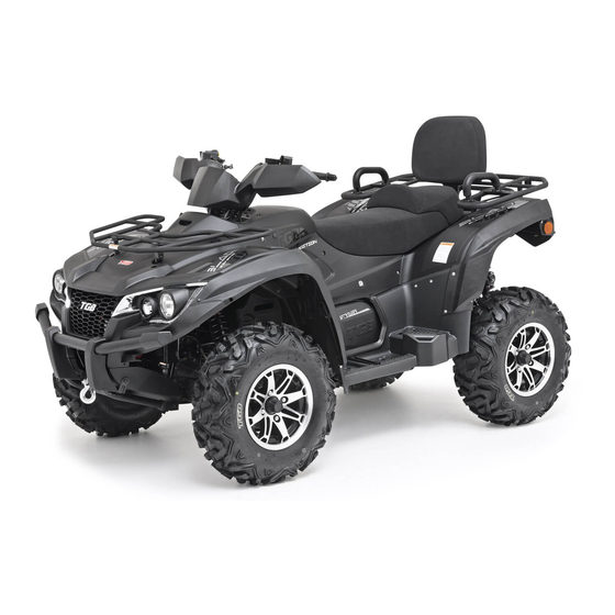
- Page 1 BLADE 1000 EPS IRS 4X4 BLADE 1000 EPS SE IRS 4X4 Recreation Utility Vehicle Assembly Manual...
- Page 2 The procedures below are described in the information required for the correct assembly order that the procedures are carried out of this TGB vehicle prior to delivery to the correctly and completely. Failure to do so can customer. Since some external parts of the...
-
Page 3: Table Of Contents
Table of Contents PAGE CONTENT Symbols Used on Outer Cover Crate Handling Uncrating 8-11 Parts Check Assembly (Shock Absorber) 12-13 Assembly (Rear A-arm Protector Cover) Assembly (Wheels) Assembly (Handlebar) 13-14 Assembly (Handlebar Cover / Hand Guard) Assembly (Shift Holder) Assembly (Front Bumper) Assembly (Rear Hand Hold) Assembly (Rear Carrier) - Page 4 Table of Contents PAGE CONTENT Assembly (Muffler Ornamental Cover) Assembly (Seat) Assembly (Battery)
-
Page 5: Symbols Used On Outer Cover
Symbols Used on Outer Cover (1) Indicates correct upright position of the transport package. (2) Transport package must be kept away from rain. (3) Contents of the transport package are fragile, therefore the package must be handled with care. (4) Up to 4 of the transport packages can be piled up. (5) Do not insert from the symbol position of the transport package. -
Page 6: Crate Handling
Crate Handling Warning 1. Always handling the crated vehicle by a forklift, include stacking/un-stacking and storing. 2. Never stacking up over the indicated high shown on the crate outer cover. Caution 1. Insert the fork according to the indication position where shown on the crate outer cover. 2. - Page 7 2. Remove top cage braces (A), and be careful to avoid damage to the vehicle plastics and the seat leather during the action. 3. Remove the bolts (A), and then lay down LH & RH side diagonal braces (B) to disengage its sockets from the pallet.
-
Page 8: Parts Check
Parts Check Note There may be minor differences in appearance between these illustrations and the actual vehicle parts. Remove the parts and check the crate base and packaged materials carefully for lost parts. Check the parts against the illustrations. In the following charts under Remarks, D=diameter in millimeters, and L=length in millimeters, and P=Pitch. - Page 9 Part Name Remark Rear Shock Absorber Shock Absorber Bolts D=10, L=48, P=1.25 Shock Absorber Nuts D=10, P=1.25 Rear A-arm Protector Cover (LH) Rear A-arm Protector Cover (RH) Rear A-arm Protector Cover Bolts D=6, L=16 Muffler Ornamental Cover Hex. Socket Bolts Rear Carrier Comp.
- Page 10 Part Name Remark Handlebar Upper Bracket Handlebar Lower Bracket Bottom Bracket Bolts D=6, L=16, P=1.0 Pan Head Screw D=6, L=16 Bolts D=8, L=80, P=1.25 Fuel Cap Shift Shaft Holder Tool Bag...
- Page 11 Part Name Remark Handlebar Front Cover Handlebar Rear Cover comp. Hand Guards Bracket (RH) Hand Guards Bracket (LH) Flange Screws D=5, L=16 Bolt D=8, P=1.25 (Right-Handed Thread) Bolt D=8, P=1.25 (Lift-Handed Thread) Washers φ8.4 x 15.5 x 1.2t Tapping Screw D=4, L=16 Tapping Screw D=4, L=12...
-
Page 12: Assembly (Rear A-Arm Protector Cover)
Assembly After opening the crate, lift the vehicle out from the packing crate, and place the vehicle on a suitable rack, or using jacks to raise the vehicle for assembling process. Warning Torque wrench tightening specifications must be adhered to. Warning 1. -
Page 13: Assembly (Handlebar Cover / Hand Guard)
Install the below flange bolt (A) from rear to front, and then tighten the nut (B) to 450~550 kgf-cm torque. 3. Rear A-arm Protector Cover There are marks (LH / RH) inside the a-arm protector cover, according to the mark to assemble the protector cover to the corresponding a-arm. - Page 14 Assemble the master cylinder on the left handlebar and close to switch assy., and make the top cover of the master cylinder parallel to the ground. And then tighten the bolt on the upper side of the master cylinder bracket, and then the lower side bolt. Make sure the “UP”...
-
Page 15: Assembly (Rear Hand Hold)
7. Shift Holder Screw the shift holder into the shift axle (A) with appropriate depth, and tighten the nut (B) under on the axle. 8. Front Bumper Take off the 4 bolts and washers on the front lower shield (A), and assemble back with front bumper. - Page 16 11. Muffler Ornamental Cover The ornamental cover (A) with slight adjustable ability, please adjust to the correct position to cover the skew deviation. And then tighten the 3 (B) bolts. Warning Never operate while the muffler with high temperature. 12. Seat Take off the 2 nuts on the passenger seat and then assemble to the mounting points (A) on the main seat.
Need help?
Do you have a question about the BLADE 1000 EPS IRS 4X4 and is the answer not in the manual?
Questions and answers
Где посмотреть номер двигателя