Table of Contents
Advertisement
Quick Links
Advertisement
Table of Contents

Related Manuals for Insportline IN 10893 inCondi UB30m


Summary of Contents for Insportline IN 10893 inCondi UB30m
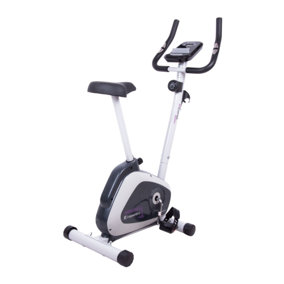
- Page 1 USER MANUAL – EN IN 10893 Exercise Bike inSPORTline inCondi UB30m...
-
Page 2: Table Of Contents
CONTENTS SAFETY FUNCTION ..........................3 TOOL KIT ..............................4 EXPLODED VIEW ........................... 5 PARTS LIST ............................6 ASSEMBLY ............................. 7 RESISTNCE ADJUSTMENT ......................... 14 CONSOLE INSTRUCTIONS ......................... 15 iBIKING+ INSTRUCTIONS ........................17 FAT BURNING ............................22 TERMS AND CONDITIONS OF WARRANTY, WARRANTY CLAIMS ..........23... -
Page 3: Safety Function
PREFACE Let’s start a fearless adventure in knowing what to do when no one’s there telling you what to do. BUT Before that please read the following. SAFETY FUNCTION This exerciser is made for home use only, and tested up to a max body weight of 120kg. 1. -
Page 4: Tool Kit
TOOL KIT These are all the accessories you will need to complete the assembly of your product. The following accessories are loosely assembled to the frame or master component and will need to be removed prior to assembly. -
Page 5: Exploded View
EXPLODED VIEW... -
Page 6: Parts List
PARTS LIST Part No. Description Q’ty Handlebar Handlebar Upright Main Frame Saddle Stem Front Stabilizer Rear Stabilizer Pedal Crank and Drive Wheel Flywheel Pulley Bracket Console Handlebar Grip Foam Pulse Sensor Pad M8 x 25 mm Allen Bolt Pulse Sensor Wire Tension Controller Saddle Saddle Stem Insert... -
Page 7: Assembly
M8 Nylon Lock Nut M8 Lock Nut M8 x 75 mm Carriage Bolt M8 x 20 mm Allen Bolt M8 Dome Nut M8 Curved Washer M8 Spring Washer M8 Flat Washer Allen Bolt 4.2 x 20mm Self-tapping Screw Bottle Cage ASSEMBLY Carefully unpack each component, checking against the parts list that you have all the necessary parts to complete the assembly of your product. - Page 8 Note: Do NOT FULLY TIGHTEN any Bolts, Nuts or Fittings at this stage unless specifically instructed to do so. STEP 2: Assemble the Pedals (Left and Right) (21L & 21R) to the Pedal Crank (7) (see note). Both Pedals MUST be tightened securely otherwise damage may occur to the Crank. Fit the Pedal Straps (Marked L and R) ensuring a snug, but not tight fit with your normal footwear.
- Page 9 STEP 3. Remove the 3 x M8 Nylon Locknuts (36) and 3 x M8 Flat Washers (43) from the underside of the Saddle (16). Attach the Saddle (16) to the Saddle Stem (4) then loosely refit the 3 x M8 Flat Washers (43) and 3 x M8 Nylon Locknuts (36).
- Page 10 STEP 4: Slide the assembled Saddle Stem (4) into the Main Frame (3), select the desired height to allow for a knee bend at the bottom of the pedaling action and secure in place with the Saddle Adjustment Knob (18). Align the Saddle and tighten the 3 x M8 Nylon Locknuts (36) securely.
-
Page 11: Handlebar
STEP 5: a) Place the end of the 8-stage Tension Control Cable (15) into the spring hook of the Lower Tension Cable (32). b) Pull the 8-stage Tension Control Cable upwards against the spring pressure and push it into the gap on the metal bracket of the Lower Tension Cable as shown. c) Complete the fitting as shown and if necessary, close the open section of the metal bracket slightly with a pair of pliers as this will help to retain the cables. - Page 12 STEP 6: Fit the Handlebar (1) onto the Handlebar Upright (2) with 2 x M8 x 25mm Allen Bolts (13), 2 x M8 Curved Washers (41), 2 x M8 Spring Washers (42).
-
Page 13: Console
STEP 7: Attach the Console (10) to the Handlebar Upright (2) using 2 x M5 x 10mm Screws (30). Connect the Upper Link Wire (33) and Pulse Sensor Wire (14) into the back of Console (10). -
Page 14: Resistnce Adjustment
RESISTNCE ADJUSTMENT To adjust the pedaling resistance during use, start by turning the Tension Controller Knob (15) fully COUNTER-CLOCKWISE at the start of your workout. Gradually increase the pedaling resistance by turning the Tension Controller Knob CLOCKWISE as required. When you have finished your routine, turn the Tension Controller Knob (15) fully COUNTER- CLOCKWISE again to ensure that the Tension Controller Cable is not under tension when your Magnetic Bike is not in use. -
Page 15: Console Instructions
CONSOLE INSTRUCTIONS DISPLAY FUNCTION SCAN The sequence of display: TMR→SPD→ DST→CAL→ODO→PULSE In SCAN mode, press MODE key to choose other functions. • Automatically scan through each mode in sequence every 6 seconds. • SPEED (SPD) W/O any signal been transmitted into the monitor for 4 seconds, SPEED will display “0.0” •... - Page 16 With setting the target value, calories will count down from your target calorie to 0, and as 0 is • achieved calorie alarm. Range 0.0~9999 Cals • Calorie count on the display only serves as a general guideline. For detail calorie consumption •...
-
Page 17: Ibiking+ Instructions
If there is no signal when you pedal, please check if the cable is well connected. • Drawing A Drawing B Drawing C Drawing D Note: 1. Compatible with iOS and Android system. 2. Console and mobile device connection via Tunelinc, once connecting, the display will be off. - Page 18 STARTING iBIKING+ Step 1 Step 2 Step 3 Entering the App Press “Tunelinc” icon Successful connection: • • • again to confirm Press “Tunelinc” icon • Connection not success • yet: MAIN FUNCTION OF iBIKING+ The main functions of iBiking+ are: 1. training 2. gym center 3. setting 4. information TRAINING The main function of training are: 1.
- Page 19 Main layout Workout summary Share layout After starting exercise user can press pause from console control to stop any time. • When finish, the workout summary can post on Facebook, Twitter, Weibo. • You can setting 2 values: 1. heart rate 2.time Main layout: *1 „x“...
- Page 20 2. My favorite There are five default routes in my favorites. User selected route can save in my favorites. Main layout: Choose vision mode Shows elevation and length of shows the exercise information: the route time, distance, calories, speed, rpm, heart rate 3.
- Page 21 Step 3 Step 4 Press „MapMyFitness“ Use the route database from MapMyFitness SETTING Log in by user’s Google/ Facebook account or create a new account. INFORMATION All the workout histories show up.
-
Page 22: Fat Burning
Note: 1. Without receiving any reply comment of communications protocol, the APP would continue sending signal and wait for acknowledging. And over 15 seconds the Tunelinc would off line, and user needs to reset (such as: phone, message, or any sound disturbance comes in. In 15 seconds the connection would continue but if over 15 seconds, user needs to reset.) 2. -
Page 23: Terms And Conditions Of Warranty, Warranty Claims
Pulse rate chart: SUCCESS Even after a short period of regular exercises you will realize that you constantly have to increase the pedaling resistance to reach your optimum pulse rate. The units will be continuously easier and you will feel a lot fitter during your normal day. For this achievement you should motivate yourself to exercise regularly. - Page 24 “The Buyer who is not the End Customer” is a Businessman that buys Goods or uses services for the purpose of using the Goods or services for his own business activities. The Buyer conforms to the General Purchase Agreement and business conditions to the extent specified in the Commercial Code.
- Page 25 VAT ID: CZ26847264 Phone: +420 556 300 970 E-mail: eshop@insportline.cz reklamace@insportline.cz servis@insportline.cz Web: www.insportline.cz INSPORTLINE s.r.o. Headquarters, Warranty & Service centre: Elektricna 6471, 911 01 Trencin, Slovakia CRN: 36311723 VAT ID: SK2020177082 Phone: +421(0)326 526 701 E-mail: objednavky@insportline.sk reklamacie@insportline.sk servis@insportline.sk Web: www.insportline.sk...
Need help?
Do you have a question about the IN 10893 inCondi UB30m and is the answer not in the manual?
Questions and answers