Table of Contents
Advertisement
Quick Links
Advertisement
Table of Contents

Related Manuals for Insportline IN 10895 inCondi UB20m


Summary of Contents for Insportline IN 10895 inCondi UB20m
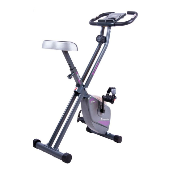
- Page 1 USER MANUAL – EN IN 10895 Exercise Bike inSPORTline inCondi UB20m Made in PRC...
-
Page 2: Table Of Contents
CONTENTS SAFETY INSTRUCTIONS ........................3 ASSEMBLY ............................. 5 EXPLODED VIEW ........................... 8 PARTS LIST ............................9 RESISTANCE ADJUSTMENT ......................11 LEVELLING THE BIKE .......................... 11 HOW TO FOLD ............................. 11 HOW TO ADJUST ..........................12 CONTROL PANEL OPERATION ......................13 iBIKING+ INSTRUCTIONS ........................ -
Page 3: Safety Instructions
SAFETY INSTRUCTIONS Before you undertake any program of exercise that will increase cardiovascular activity please be sure to consult with your doctor. Frequent strenuous exercise should be approved by your doctor and proper use of your product is essential. Please read this manual carefully before commencing assembly of your product or starting to exercise. -
Page 4: Hardware
CHECK LIST Main Frame (7), Rear Frame (2) Saddle (24) Exercise monitor (16), Handlebar (1) Saddle Support (6) Front Stabilizer (9) Adjuster Knob (26) Locking Pin (3) Rear Stabilizer (8) Pedal (29L), Pedal (29R) HARDWARE:... -
Page 5: Assembly
ASSEMBLY STEP 1: Assemble Rear & Front Stabilizer, Pedal (L/R) -
Page 6: Saddle
STEP 2: Assemble Saddle... - Page 7 STEP 3: Assemble Handlebar & Exercise Monitor Complete!
-
Page 8: Exploded View
EXPLODED VIEW... -
Page 9: Parts List
PARTS LIST Q’ty Part No. Description Handlebar Rear Frame Locking Pin M5*10 Screw Oval Line plug Saddle Support Main Frame Rear Stabilizer Front Stabilizer Crank (R&L) Main Shaft Lower Drive Wheel Shaft Magnetic Bracket Round Steel Handle Grip Foam Exercise Monitor Pulse Sensor Pad Chain Cover (U) Tension Control knob... - Page 10 Upper Drive Wheel Sensor Bracket Magnet Crank Guard Trim Pulley Waved Washer Spring Washer M4*20mm Self-tapping Screw M5*15mm Screw M6*12mm Allen Bolt M5*50mm Screw Drive Belt 230J Drive Belt 220J Spring M8*20 mm Allen Bolt M8 x 65 mm Carriage Bolt M6*40 mm Screw M6*15 mm Screw M4*20 Self-tapping Screw...
-
Page 11: Resistance Adjustment
Handlebar cap RESISTANCE ADJUSTMENT To ensure smooth efficient cycling action, the tension belt braking system on your Exercise Cycle has been correctly adjusted by our factory during production. To adjust the pedaling resistance during use, start by turning the Tension Control (19) fully ANTI- CLOCKWISE at the start of your workout. -
Page 12: How To Adjust
HOW TO ADJUST The Saddle Support has “Max” Sign to show the maximum height of Saddle. You should not exceed this height. Unscrew the Seat Adjustment Knob (26) a couple of turns then pull the knob outwards to release the Seat Support Tube (6). Position the Seat Support Tube to the desired height allowing for a slight bend in the knee at the lowest pedal position and retighten the Seat Adjustment Knob (26). -
Page 13: Control Panel Operation
CONTROL PANEL OPERATION FUNCTION 0:00 – 99:59 (min) TIME 0.0 – 999.9 (km/h) SPEED 0.0 – 999.9 (km) DISTANCE 0 – 9999 (km) ODOMETER 0.0 – 999.9 (Kcal) CALORIES 40 – 240 (BPM) PULSE 1. MONITOR 2. ODOMETER 3. CALORIES 4. -
Page 14: Ibiking+ Instructions
POWER ON/OFF Power on: LCD will display all segments with Beep sound as Drawing A. Power off: Without any signal been transmitted into the monitor for 4 minutes, and the monitor enter to SLEEP. OPERATION 1. When monitor power on (or press MODE, RESET key and hold for 3 seconds), LCD will display all segments with Beep sound for one second and enter to SCAN mode as Drawing B. - Page 15 STARTING iBIKING+ Step 1 Step 2 Step 3 Press “Tunelinc” icon Entering the App Successful connection: again to confirm Press “Tunelinc” icon Connection not success yet: MAIN FUNCTION OF iBIKING+ The main functions of iBiking+ are: 1. training 2. gym center 3. setting 4. information TRAINING The main function of training are: 1.
- Page 16 Main layout Workout summary Share layout After starting exercise user can press pause from console control to stop any time. When finish, the workout summary can post on Facebook, Twitter, Weibo. You can setting 2 values: 1. heart rate 2.time Main layout: *1 „x“...
- Page 17 2. My favorite There are five default routes in my favorites. User selected route can save in my favorites. Main layout: Choose vision mode Shows elevation and length of shows the exercise information: the route time, distance, calories, speed, rpm, heart rate 3.
- Page 18 Step 3 Step 4 Press „MapMyFitness“ Use the route database from MapMyFitness SETTING Log in by user’s Google/ Facebook account or create a new account. INFORMATION All the workout histories show up. Note: 1. Without receiving any reply comment of communications protocol, the APP would continue sending signal and wait for acknowledging.
-
Page 19: Terms And Conditions Of Warranty, Warranty Claims
needs to reset.) 2. Tunelinc’s audio cable connector is 4 pin, and the length limit is 50cm. 3. Tunelinc’s audio cable be sure to use the factory supplied to achieve high quality transmission. If using non-original audio cable, not only affect the transmit performance but also may happened unexpected result and we cannot provide assistance by then. - Page 20 Mechanical damages Regular use (e.g. wearing out of rubber and plastic parts, joints etc.) Unavoidable event, natural disaster Adjustments made by unqualified person Improper maintenance, improper placement, damages caused by low or high temperature, water, inappropriate pressure, shocks, intentional changes in design or construction etc. Warranty Claim Procedure The Buyer is obliged to check the Goods delivered by the Seller immediately after taking the responsibility for the Goods and its damages, i.e.
- Page 21 VAT ID: CZ26847264 Phone: +420 556 300 970 E-mail: eshop@insportline.cz reklamace@insportline.cz servis@insportline.cz Web: www.insportline.cz INSPORTLINE s.r.o. Headquarters, Warranty & Service centre: Elektricna 6471, 911 01 Trencin, Slovakia CRN: 36311723 VAT ID: SK2020177082 Phone: +421(0)326 526 701 E-mail: objednavky@insportline.sk reklamacie@insportline.sk servis@insportline.sk Web: www.insportline.sk...
Need help?
Do you have a question about the IN 10895 inCondi UB20m and is the answer not in the manual?
Questions and answers