Advertisement
Quick Links
Advertisement

Subscribe to Our Youtube Channel
Related Manuals for Insportline UB35i


Summary of Contents for Insportline UB35i
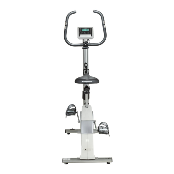
- Page 1 USER MANUAL – EN IN 11205 inSPORTline UB35i Exercise Bike...
-
Page 2: Table Of Contents
CONTENTS SAFETY INSTRUCTIONS ........................3 EXPLODED VIEW – ASSEMBLY DRAWING ..................4 PARTS LIST ............................5 HARDWARE & TOOL .......................... 7 ASSEMBLY ............................. 8 EXERCISE COMPUTER INSTRUCTIONS ................... 13 EXERCISE INSTRUCTIONS ........................ 18 TERMS AND CONDITIONS OF WARRANTY, WARRANTY CLAIMS ..........20... -
Page 3: Safety Instructions
SAFETY INSTRUCTIONS This exerciser is made for home use only, and tested up to a max body weight of 150kg. 1. Follow the steps of the assembly instructions carefully. 2. Use only original parts as delivered. 3. Place this exerciser on an even, non-slippery surface. Because of possible corrosion, the usage of any exerciser in moist areas is not recommended. -
Page 4: Exploded View - Assembly Drawing
EXPLODED VIEW – ASSEMBLY DRAWING... -
Page 5: Parts List
PARTS LIST Description Q'ty A,A-1 Console and screw Hex. screw M8xP1.25x12Lx5t Big Pulley Bushing Shaft C-1,C-3~C-13 Flywheel set Nut 3/8"-26x4.5t D-1~D-4,D-7~D9 Idler wheel set Hex. bolt M8xP1.25x20L Flat washer φ8.5xφ25x1t Flat washer φ8*φ19*2T Allen bolt M8*P1.25*16L Semi-circle washer Φ8xφ19x2t Magnetic set Hex. - Page 6 G-19 Adjusting knob for Main frame G-21 Screw M4x10L G-22 Sensor box G-23 Sensor holder G-24 Cover for handlebar post G-25 Crank (Left) Upper console cable Screw M5xP0.8x20L Handlebar post Stabilizer cap Adjustable pad Rear stabilizer Transport wheel for front stabilizer Screw M5x12L Front stabilizer K,G-20...
-
Page 7: Hardware & Tool
HARDWARE & TOOL ASSEMBLY PARTS IN THE CARTON:... -
Page 8: Assembly
ASSEMBLY STEP 1 1. Fasten front stabilizers (J-3) each with carriage bolts (N-2), flat washers (N-3), nuts (N-1) by box spanner. 2. Fasten rear stabilizers (I-3) each with carriage bolts (N-2), flat washers (N-3), nuts (N-1) by box spanner. - Page 9 STEP 2 1. Assemble the straps onto the pedals as the sketches. Adjust the ideal length of the straps according to your foot size. 2. Assemble the two pedals (G-4R/L) onto the cranks (G-25 & 26) with a screw driver by the screwdriver / box spanner.
- Page 10 STEP 3 1. Please remove the allen bolt (E-2) and semicircle washers (E-3) and flat washers (E-1) from the main frame (G-10). 2. Take the handlebar post (H-3) and pass it through the handlebar post cover (G-24). 3. Install the handlebar post (H-3) to the main frame with 2 flat washers (E-1), 2 semicircle washers (E-3), and 4 allen bolts (E-2).
- Page 11 STEP 4 1. Pass the hand-pulse wire (M-4) through the hole. 2. Attach the handlebar (M-6) to the hand post metal cover. 3. Place the handlebar cover (N-5) on the handlebar (M-6). Insert the T- knob (N-4) into the metal cover (N-5). Ensure again it is tightened very well. STEP 5 1.
- Page 12 CONNECTION THE TUNELINC WIRE Please connect the wire of Tunelinc to the audio port on the mobile phone or pad as illustrated drawing.
-
Page 13: Exercise Computer Instructions
EXERCISE COMPUTER INSTRUCTIONS BUTTON FUNCTIONS Increase resistance and WATT level or function value during exercise. Up ▲ Setting or function selection. Decrease resistance and WATT level or function value during exercise. Down ▼ Setting or function selection. Confirm setting or selection. Mode In MANUAL mode, press it to choose single function display. - Page 14 .Range 0 ~ 999 WATT .Workout power consumption .Display range 0~350 PULSE .Pulse bpm displayed during exercise. .Pulse alarm when over preset target pulse. Range 0-30~230. MANUAL .Manual mode workout. PROGRAM .12 PROGRAM selection. H.R.C .Target HR training mode. WATTS .
- Page 15 Drawing 6 Drawing 7 Manual Mode Press START in main menu may start workout in Manual mode directly. 1. Press UP or DOWN button to select workout program, choose M and press MODE to enter. 2. Press UP or DOWN to adjust load level (Drawing 8), preset value 1. The adjustment cannot be cycled.
- Page 16 Drawing 14 Drawing 15 Drawing 16 H.R.C Mode 1. Press UP or DOWN to select workout program, choose H.R.C. and press MODE to enter (Drawing 17). Input user AGE and confirm by MODE. (Drawing 18) (Each time when quit HRC mode, user must reset AGE.) 2.
- Page 17 4. Press START/STOP key to start workout. During workout, system will adjust load level automatically based on user training status. User can also press UP and DOWN to adjust Watt level. 5. Press START/STOP key to pause workout. Press RESET to reverse to main menu. Drawing 24 Drawing 25 Drawing 26...
-
Page 18: Exercise Instructions
Program profile: I-Console+ APP User can connect console to tablet for APP function through below method: Plug in audio cable into Tunelinc hole to connect the console to tablet. Turn on i-Console+ app on tablet, and start workout with tablet. EXERCISE INSTRUCTIONS Using your EXERCISE BIKE provides you with several benefits, it will improve your physical fitness, tone muscle and in conjunction with a calorie controlled diet help you lose weight. - Page 19 below. Each stretch should be held for approximately 30 seconds, do not force or jerk your muscles into a stretch - if it hurts, STOP. THE EXERCISE PHASE This is the stage where you put the effort in. After regular use, the muscles in your legs will become stronger.
-
Page 20: Terms And Conditions Of Warranty, Warranty Claims
The important factor here is the amount of effort you put in. The harder and longer you work the more calories you will burn. Effectively this is the same as if you were training to improve your fitness, the difference is the goal. TERMS AND CONDITIONS OF WARRANTY, WARRANTY CLAIMS General Conditions of Warranty and Definition of Terms All Warranty Conditions stated hereunder determine Warranty Coverage and Warranty Claim... - Page 21 VAT ID: CZ26847264 Phone: +420 556 300 970 E-mail: eshop@insportline.cz reklamace@insportline.cz servis@insportline.cz Web: www.insportline.cz INSPORTLINE s.r.o. Headquarters, Warranty & Service centre: Elektricna 6471, 911 01 Trencin, Slovakia CRN: 36311723 VAT ID: SK2020177082 Phone: +421(0)326 526 701 E-mail: objednavky@insportline.sk reklamacie@insportline.sk servis@insportline.sk Web: www.insportline.sk...
Need help?
Do you have a question about the UB35i and is the answer not in the manual?
Questions and answers