Table of Contents
Advertisement
Quick Links
Advertisement
Table of Contents

Related Manuals for Cembre RDS-14P


Summary of Contents for Cembre RDS-14P
- Page 1 14 M 113 E ENGLISH RAIL SAW RDS-14P RDS-14P.78...
- Page 2 Before using the machine, carefully read the instructions contained in this manual. SAVE THESE INSTRUCTIONS: this manual contains important safety and operating instructions for the machine. It is mandatory to wear approved personal protective equip- ment, such as: - Flame retardent clothing. - A helmet, goggles or face shield.
- Page 3 The machine should only be used by trained, competent personnel. • Do not use the RAIL SAW for purposes other than those intended by Cembre or for grinding operations using the side surface of the cutting disc as this may break and cause serious injury.
-
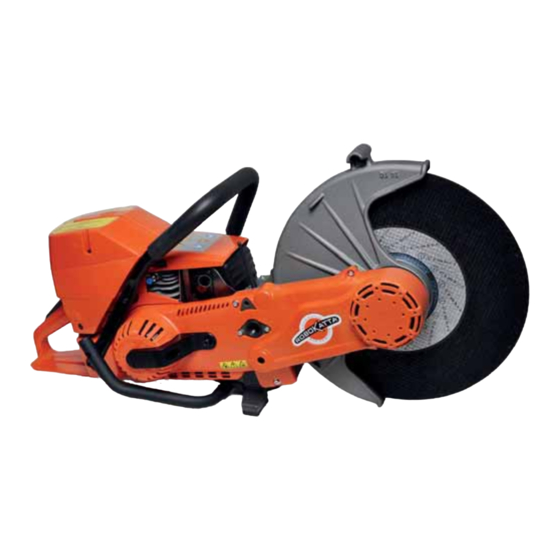
Page 4: Main Components
Descriptions and possible confi gurations: • RDS-14P RDS-14P.78 * • AA-RDS • SA-RDS • • RDS-14P-AA RDS-14P.78-AA * • • RDS-14P-SA RDS-14P.78-SA * (*) Rail saw suitable for cutting discs with hub diameter of 22.2 mm (7/8”). Main components (Ref. Fig. 1 page 5): 14 –... - Page 5 FIG. 1...
-
Page 6: General Characteristics
– Cutting group: – n° of revs of drive shaft: ........................4,700 RPM – drive shaft diameter (RDS-14P): .................... 25.4 mm (1”) – drive shaft diameter (RDS-14P.78): ................... 22.2 mm (7/8”) – max. diameter of suitable cutting disc: ................406 mm (16”) –... -
Page 7: Safety Guard
3.2) Safety devices on the machine The safety devices supplied on the RAIL SAW and listed below must be fully functional and checked before each use. If this is not the case do not use the machine and contact Cembre for any repairs. -
Page 8: Technical Details
3.3) Auxiliary switching device REAR VIEW Aerial STOP button (1) (switches the rail saw off ) Hook RESET button (2) (stops the air fi lter cleaning alarm) Protective rubber case Battery compartment TECHNICAL DETAILS: frequency: 433 Mhz max. distance: 5 metres power: CR2032 Lithium cell battery Cover... - Page 9 3.4) Abrasive cutting discs For maximum performance, use the rail saw in conjunction with the high quality C-Rex range Cembre discs listed below, in compliance with the requirements of the standard EN 12413 for bonded abrasives: Dimensions Peripheral Compatibility DISC...
- Page 10 4.1) Fuel mixture preparation Risk of explosion or fi re, petrol is extremely fl ammable, handle with caution. Risk of intoxication, avoid inhalation of petrol vapours. Risk of irritation, avoid prolonged and repeated contact with skin. The rail saw has a 2-stroke air cooled engine which runs on an oil-petrol mix; for the correct dosage of oil use the measure supplied, according to the following proportions: 1:50 (2 %) of specialist synthetic 2 stroke engine oil (e.g.
-
Page 11: Mounting The Cutting Disc
20-25 Nm. During the tightening phase counteract the movement of the disc with one hand. NOTE: with the RDS-14P.78 type rail saw, check that the disc hub is suited to the 7/8” shaft. NEVER use cutting discs with a 1”... -
Page 12: Starting And Stopping The Engine
Fig. a 4.4) Starting and stopping the engine Always start the machine at a safe distance from the re- fuelling area. Start the engine only when the abrasive cutting disc is mounted. Fig. b Before starting, check that the abrasive cutting disc can rotate freely. - Page 13 Fig. f Wait until the disc has completely stopped before mounting the machine on the support arm. – Restart the engine (Fig. f). The engine can be turned off : • On the machine: release the accelerator and turn the main switch to the right into the STOP position.
- Page 14 The AA-RDS automatic support arm allows the machine to cut rail without operator contact as it picks up the motion from the rail saw and automatically simulates the movement of the ope- rator during cutting; the rail saw is guided to obtain a perfectly perpendicular and straight cut. Furthermore,this arm safely supports the rail saw in a comfortable position to facilitate fi...
- Page 15 Serial Number Numéro de série Seriennummer Número de serie Numero di Matricola...
- Page 16 NOTE: The fi xing clamp is designed to allow a precise and secure tightening of the arm on Vignole type rails; for the fi xing of the arm on diff erent rail types contact Cembre. Type Vignole Contact Cembre...
- Page 17 15 for optimal function of the rail saw under the following conditions of use: – Cembre ø 350 mm cutting disc type CRDL 4381 or CRDL 4387 or similar. – Rail to be cut type UIC 60 or similar.
- Page 18 - Rotate the blue lever (18) in order to lock it in the external position, to facilitate this operation it is advisable to keep the arm slightly raised from the base by gripping it in position (A) with one hand. - At the same time unlock red lever (17).
- Page 19 IMPORTANT (Ref. to fi gure below): Make sure that at the end of rotation, lever (L) is resting on the bushes (A) so that the spring rod is positioned downwards; otherwise, it will not be possible to support the rail saw and perform the cut. 6.3.1) Rotating the interface group The overturning of the arm from one side of the rail to the other also requires the rotation of the interface group...
- Page 20 The figure shows the correct positioning of the rail saw supported by the arm on the two sides of the rail, in stationary position. 6.4) Mounting/dismounting the rail saw on the automatic support arm Before mounting the rail saw on the support arm: Check the gear (8) is in the downward position as described in §...
- Page 21 WARNING: WARNING: - Always consult your employer’s rules and procedures to cut rails in presence of electrical traction return current. - Never leave the rail saw unattended while cutting. - Make sure that everyone keeps a safe distance away from the cutting zone. - During the cutting operation move to a safe distance and always keep the auxiliary switching device close to hand if any problems occur during cutting.
- Page 22 – With the disc in contact with the rail, completely release the arm. – The rail saw will automatically perform regular alternate movements simulating the cutting action of an operator. During operation always keep a safe distance and always monitor the cutting process in order to readily intervene in case of problems.
- Page 23 If the rail saw stops at the rail head shortly after starting the cut, it means that the cutting force is too high: rotate the adjustment ring a couple of turns towards higher values in order to put more load on the contrast spring. If the rail saw stops at the intersection between the rail web/foot towards the end of the cut, it means that the cutting force is insuffi...
- Page 24 Description 1. Rail saw locking handle 2. Mobile arm 3. Sliding track 4. Clamp locking wheel/release 5. Cutting reference plate 6. Fixed jaw clamp 7. Stationary positioning lever 8. Knob to adjust arm height Serial Number 9. Vertical arm Numéro de série 10.
- Page 25 8.1) Attaching the arm to the rail Place the arm on the rail, the fi xed clamp is the same to that of the AA-RDS arm and follow the procedure described in § 6.1. 8.2) Adjusting the height of the manual arm The SA-RDS support arm can be adjusted to met the cutting requirements based on the rail dimensions and to allow the operator to adopt...
- Page 26 The fi gure shows the correct positioning of the rail saw on the support arm on both sides of the rail. 8.4) Mounting/dismounting the rail saw on the manual support arm Before mounting the rail saw on the support arm, make sure that clamp (6) is fi rmly locked as described in §...
- Page 27 WARNINGS: - Always consult your employer’s rules and procedures to cut rails in presence of electrical traction return current. - Follow the precautions described in § 9.1. - Ensure that everyone keeps the safety distance from the cutting zone. - Remove aggregate (min. 15 cm) from the cutting area under the rail, to avoid interference with the cutting disc guard and to make it easier to remove the disc when the cut is fi...
- Page 28 – Start the cut by using regular alter- nate movements, maintaining a steady pressure during the whole cutting phase. The double articulation of the support arm will relieve the operator of the weight of the machine thus making the cutting operation easier.
- Page 29 To cut short rail sections, the section must be sta- bilised with appropriate fi xtures to avoid the risk of unexpected machine movement; the stabilising support Cembre type SSR1 fulfi ls this function and is available as an accessory. SSR 1...
-
Page 30: Maintenance Plan
The maintenance procedures described may be carried out by the operator. For any eventual fi ne tuning or repairs, return to Cembre. The maintenance plan provided is intended for a machine which is used daily, so intervals may vary according to usage frequency. -
Page 31: Audible Alarm
fi lter then squeezing it to get rid of excess oil. Do not use normal engine oil for this purpose, contact Cembre for suitable oil. NOTE: Do not clean the fi lter with compressed air as high pressure could damage the sponge. -
Page 32: Re-Setting The Alarm
• Paper Filter (P) (spare part code: 6003911) – Remove the insert, Take the fi lter out and shake or clean it carefully with compressed air from the inside out, to remove the dust. – Reassemble correclty. NOTE: the paper fi lter must not be washed! Depending on usage, the fi... - Page 33 The engine is equipped with a fi xed nozzle that ensures the correct supply of the blended air and fuel. If the engine is losing power or is not accelerating, clean or if necessary replace the air fi lter. If this does not resolve the problem, contact Cembre. • Carburration adjustment Fully press the accelerator a couple of times and check that the rail saw accelerates as expected.
-
Page 34: Starter Rope
10.6) Starter rope Always wear safety goggles when replacing the starter rope; the recoil spring is tensio- ned and if accidentally released may cause personal injury! • Replacing a worn or broken starter rope – Unscrew 4 screws that hold the side motor cover and remove it (Ref. - Page 35 • Replacing the recoil spring – Remove the starter pulley by unscrewing the central screw. – Remove the recoil spring carefully by grasping it with grips. – Lubricate the recoil spring with a few drops of oil and then reassemble the starter pulley and tension the spring.
-
Page 36: Replacing Belts
10.8) Replacing belts – Disassemble the side cover (Ref. to § 10.7). Replacing the timing belt: (spare part code: 6003791) Fig. a – Remove the belt from the pinion fi rst. Assemble the new belt (Refer to Fig. a) Timing belt starting from the pulley side. - Page 37 Insuffi cient oil in fuel mixture. Prepare mixture with more oil. Obstructed cooling fi ns. Clean the cooling fi ns. Check engine for seizure, contact Cembre (§ 13). - Too much exhaust Too much oil in fuel mixture. Prepare mixture with less oil.
- Page 38 During transport or storage of the machine always remove the cutting disc. To facilitate transport and protect the Rail Saw, support arms and accessories from accidental knocks and dirt, Cembre recommends the use of appropriate containers, robust wooden crate with convenient spaces.
- Page 39 Test Certifi cate supplied by Cembre together with the machine or, if no other references are available, indicate the approximate purchase date and the machine serial number.
- Page 40 CS 92014 – 91423 Morangis Cédex E-mail: sales@cembre.com E-mail: sales@cembre.co.uk E-mail: info@cembre.fr www.cembre.it www.cembre.co.uk www.cembre.fr Cembre España S.L. Cembre GmbH Cembre Inc. Calle Verano, 6 y 8 - P.I. Las Monjas Heidemannstraße 166 Raritan Center Business Park 28850 Torrejón de Ardoz - Madrid (España) 80939 München (Deutschland)
Need help?
Do you have a question about the RDS-14P and is the answer not in the manual?
Questions and answers