Table of Contents
Advertisement
Features
•
High Performance, Low Power Atmel
•
Advanced RISC Architecture
– 131 Powerful Instructions – Most Single Clock Cycle Execution
– 32 x 8 General Purpose Working Registers
– Fully Static Operation
– Up to 20 MIPS Throughput at 20MHz
– On-chip 2-cycle Multiplier
•
High Endurance Non-volatile Memory Segments
– 4/8/16/32KBytes of In-System Self-Programmable Flash program memory
– 256/512/512/1KBytes EEPROM
– 512/1K/1K/2KBytes Internal SRAM
– Write/Erase Cycles: 10,000 Flash/100,000 EEPROM
– Data retention: 20 years at 85°C/100 years at 25°C
– Optional Boot Code Section with Independent Lock Bits
In-System Programming by On-chip Boot Program
True Read-While-Write Operation
– Programming Lock for Software Security
®
®
•
Atmel
QTouch
library support
– Capacitive touch buttons, sliders and wheels
– QTouch and QMatrix
– Up to 64 sense channels
•
Peripheral Features
– Two 8-bit Timer/Counters with Separate Prescaler and Compare Mode
– One 16-bit Timer/Counter with Separate Prescaler, Compare Mode, and Capture
Mode
– Real Time Counter with Separate Oscillator
– Six PWM Channels
– 8-channel 10-bit ADC in TQFP and QFN/MLF package
Temperature Measurement
– 6-channel 10-bit ADC in PDIP Package
Temperature Measurement
– Programmable Serial USART
– Master/Slave SPI Serial Interface
– Byte-oriented 2-wire Serial Interface (Philips I
– Programmable Watchdog Timer with Separate On-chip Oscillator
– On-chip Analog Comparator
– Interrupt and Wake-up on Pin Change
•
Special Microcontroller Features
– Power-on Reset and Programmable Brown-out Detection
– Internal Calibrated Oscillator
– External and Internal Interrupt Sources
– Six Sleep Modes: Idle, ADC Noise Reduction, Power-save, Power-down, Standby,
and Extended Standby
•
I/O and Packages
– 23 Programmable I/O Lines
– 28-pin PDIP, 32-lead TQFP, 28-pad QFN/MLF and 32-pad QFN/MLF
•
Operating Voltage:
– 1.8 - 5.5V
•
Temperature Range:
°
°
– -40
C to 85
C
•
Speed Grade:
– 0 - 4MHz@1.8 - 5.5V, 0 - 10MHz@2.7 - 5.5.V, 0 - 20MHz @ 4.5 - 5.5V
•
Power Consumption at 1MHz, 1.8V, 25°C
– Active Mode: 0.2mA
– Power-down Mode: 0.1µA
– Power-save Mode: 0.75µA (Including 32kHz RTC)
®
®
AVR
8-Bit Microcontroller
®
acquisition
(1)
2
C compatible)
8-bit Atmel
Microcontroller
with 4/8/16/32K
Bytes In-System
Programmable
Flash
ATmega48A
ATmega48PA
ATmega88A
ATmega88PA
ATmega168A
ATmega168PA
ATmega328
ATmega328P
Rev. 8271D–AVR–05/11
Advertisement
Chapters
Table of Contents

Related Manuals for Atmel ATmega48A


Summary of Contents for Atmel ATmega48A
-
Page 1: Features
Features ® ® • High Performance, Low Power Atmel 8-Bit Microcontroller • Advanced RISC Architecture – 131 Powerful Instructions – Most Single Clock Cycle Execution – 32 x 8 General Purpose Working Registers – Fully Static Operation – Up to 20 MIPS Throughput at 20MHz –... -
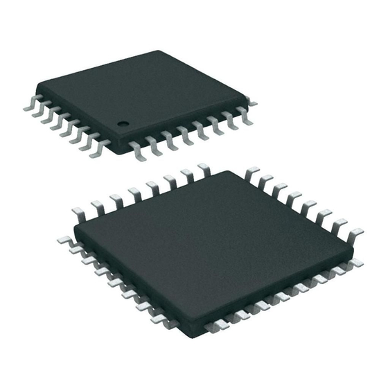
Page 2: Pin Configurations
(PCINT7/XTAL2/TOSC2) PB7 AVCC (PCINT6/XTAL1/TOSC1) PB6 AVCC (PCINT21/OC0B/T1) PD5 PB5 (SCK/PCINT5) PB5 (SCK/PCINT5) (PCINT7/XTAL2/TOSC2) PB7 NOTE: Bottom pad should be soldered to ground. NOTE: Bottom pad should be soldered to ground. Table 1-1. 32UFBGA - Pinout ATmega48A/48PA/88A/88PA/168A/168PA ADC7 AREF ADC6 AVDD 8271D–AVR–05/11... -
Page 3: Pin Descriptions
ATmega48A/PA/88A/PA/168A/PA/328/P Pin Descriptions 1.1.1 Digital supply voltage. 1.1.2 Ground. 1.1.3 Port B (PB7:0) XTAL1/XTAL2/TOSC1/TOSC2 Port B is an 8-bit bi-directional I/O port with internal pull-up resistors (selected for each bit). The Port B output buffers have symmetrical drive characteristics with both high sink and source capability. - Page 4 ATmega48A/PA/88A/PA/168A/PA/328/P The various special features of Port D are elaborated in ”Alternate Functions of Port D” on page 1.1.7 is the supply voltage pin for the A/D Converter, PC3:0, and ADC7:6. It should be externally connected to V , even if the ADC is not used. If the ADC is used, it should be connected to V through a low-pass filter.
-
Page 5: Overview
ATmega48A/PA/88A/PA/168A/PA/328/P 2. Overview The ATmega48A/PA/88A/PA/168A/PA/328/P is a low-power CMOS 8-bit microcontroller based on the AVR enhanced RISC architecture. By executing powerful instructions in a single clock cycle, the ATmega48A/PA/88A/PA/168A/PA/328/P achieves throughputs approaching 1 MIPS per MHz allowing the system designer to optimize power consumption versus processing speed. -
Page 6: Comparison Between Processors
Atmel ATmega48A/PA/88A/PA/168A/PA/328/P is a powerful microcontroller that provides a highly flexible and cost effective solution to many embedded control applications. The ATmega48A/PA/88A/PA/168A/PA/328/P AVR is supported with a full suite of program and system development tools including: C Compilers, Macro Assemblers, Program Debugger/Sim- ulators, In-Circuit Emulators, and Evaluation kits. - Page 7 1KBytes 2KBytes 2 instruction words/vector ATmega48A/PA/88A/PA/168A/PA/328/P support a real Read-While-Write Self-Programming mechanism. There is a separate Boot Loader Section, and the SPM instruction can only execute from there. In ATmega 48A/48PA there is no Read-While-Write support and no separate Boot Loader Section.
-
Page 8: Resources
® acquisition methods. Touch sensing can be added to any application by linking the appropriate Atmel QTouch Library for the AVR Microcontroller. This is done by using a simple set of APIs to define the touch chan- nels and sensors, and then calling the touch sensing API’s to retrieve the channel information and determine the touch sensor states. -
Page 9: Avr Cpu Core
ATmega48A/PA/88A/PA/168A/PA/328/P 7. AVR CPU Core Overview This section discusses the AVR core architecture in general. The main function of the CPU core is to ensure correct program execution. The CPU must therefore be able to access memories, perform calculations, control peripherals, and handle interrupts. -
Page 10: Alu - Arithmetic Logic Unit
SPI, and other I/O functions. The I/O Memory can be accessed directly, or as the Data Space locations following those of the Register File, 0x20 - 0x5F. In addition, the ATmega48A/PA/88A/PA/168A/PA/328/P has Extended I/O space from 0x60 - 0xFF in SRAM where only the ST/STS/STD and LD/LDS/LDD instructions can be used. - Page 11 ATmega48A/PA/88A/PA/168A/PA/328/P specified in the Instruction Set Reference. This will in many cases remove the need for using the dedicated compare instructions, resulting in faster and more compact code. The Status Register is not automatically stored when entering an interrupt routine and restored when returning from an interrupt.
-
Page 12: General Purpose Register File
ATmega48A/PA/88A/PA/168A/PA/328/P General Purpose Register File The Register File is optimized for the AVR Enhanced RISC instruction set. In order to achieve the required performance and flexibility, the following input/output schemes are supported by the Register File: • One 8-bit output operand and one 8-bit result input •... -
Page 13: Stack Pointer
ATmega48A/PA/88A/PA/168A/PA/328/P 7.4.1 The X-register, Y-register, and Z-register The registers R26...R31 have some added functions to their general purpose usage. These reg- isters are 16-bit address pointers for indirect addressing of the data space. The three indirect address registers X, Y, and Z are defined as described in Figure 7-3. -
Page 14: Instruction Execution Timing
ATmega48A/PA/88A/PA/168A/PA/328/P 7.5.1 SPH and SPL – Stack Pointer High and Stack Pointer Low Register 0x3E (0x5E) SP15 SP14 SP13 SP12 SP11 SP10 0x3D (0x5D) Read/Write Initial Value RAMEND RAMEND RAMEND RAMEND RAMEND RAMEND RAMEND RAMEND RAMEND RAMEND RAMEND RAMEND RAMEND... -
Page 15: Reset And Interrupt Handling
ATmega48A/PA/88A/PA/168A/PA/328/P Reset and Interrupt Handling The AVR provides several different interrupt sources. These interrupts and the separate Reset Vector each have a separate program vector in the program memory space. All interrupts are assigned individual enable bits which must be written logic one together with the Global Interrupt Enable bit in the Status Register in order to enable the interrupt. - Page 16 ATmega48A/PA/88A/PA/168A/PA/328/P Assembly Code Example in r16, SREG ; store SREG value ; disable interrupts during timed sequence sbi EECR, EEMPE ; start EEPROM write sbi EECR, EEPE out SREG, r16 ; restore SREG value (I-bit) C Code Example char cSREG;...
-
Page 17: Avr Memories
ATmega48A/PA/88A/PA/168A/PA/328/P 8. AVR Memories Overview This section describes the different memories in the ATmega48A/PA/88A/PA/168A/PA/328/P. The AVR architecture has two main memory spaces, the Data Memory and the Program Mem- ory space. In addition, the ATmega48A/PA/88A/PA/168A/PA/328/P features an EEPROM Memory for data storage. All three memory spaces are linear and regular. - Page 18 ATmega48A/PA/88A/PA/168A/PA/328/P Figure 8-1. Program Memory Map ATmega 48A/48PA Program Memory 0x0000 Application Flash Section 0x7FF Figure 8-2. Program Memory Map ATmega88A, ATmega88PA, ATmega168A, ATmega168PA, ATmega328 and ATmega328P Program Memory 0x0000 Application Flash Section Boot Flash Section 0x0FFF/0x1FFF/0x3FFF 8271D–AVR–05/11...
-
Page 19: Sram Data Memory
ATmega48A/PA/88A/PA/168A/PA/328/P SRAM Memory is organized. The ATmega48A/PA/88A/PA/168A/PA/328/P is a complex microcontroller with more peripheral units than can be supported within the 64 locations reserved in the Opcode for the IN and OUT instructions. For the Extended I/O space from 0x60 - 0xFF in SRAM, only the ST/STS/STD and LD/LDS/LDD instructions can be used. -
Page 20: Eeprom Data Memory
Next Instruction EEPROM Data Memory The ATmega48A/PA/88A/PA/168A/PA/328/P contains 256/512/512/1Kbytes of data EEPROM memory. It is organized as a separate data space, in which single bytes can be read and written. The EEPROM has an endurance of at least 100,000 write/erase cycles. The access between the EEPROM and the CPU is described in the following, specifying the EEPROM Address Reg- isters, the EEPROM Data Register, and the EEPROM Control Register. -
Page 21: I/O Memory
Summary” on page 533. All ATmega48A/PA/88A/PA/168A/PA/328/P I/Os and peripherals are placed in the I/O space. All I/O locations may be accessed by the LD/LDS/LDD and ST/STS/STD instructions, transferring data between the 32 general purpose working registers and the I/O space. I/O Registers within the address range 0x00 - 0x1F are directly bit-accessible using the SBI and CBI instructions. -
Page 22: Register Description
Read/Write Initial Value • Bits [15:9] – Reserved These bits are reserved bits in the ATmega48A/PA/88A/PA/168A/PA/328/P and will always read as zero. • Bits 8:0 – EEAR[8:0]: EEPROM Address The EEPROM Address Registers – EEARH and EEARL specify the EEPROM address in the 256/512/512/1Kbytes EEPROM space. - Page 23 ATmega48A/PA/88A/PA/168A/PA/328/P • Bits 5, 4 – EEPM1 and EEPM0: EEPROM Programming Mode Bits The EEPROM Programming mode bit setting defines which programming action that will be trig- gered when writing EEPE. It is possible to program data in one atomic operation (erase the old value and program the new value) or to split the Erase and Write operations in two different operations.
- Page 24 ATmega48A/PA/88A/PA/168A/PA/328/P Caution: An interrupt between step 5 and step 6 will make the write cycle fail, since the EEPROM Master Write Enable will time-out. If an interrupt routine accessing the EEPROM is interrupting another EEPROM access, the EEAR or EEDR Register will be modified, causing the interrupted EEPROM access to fail.
- Page 25 ATmega48A/PA/88A/PA/168A/PA/328/P Assembly Code Example EEPROM_write: ; Wait for completion of previous write sbic EECR,EEPE rjmp EEPROM_write ; Set up address (r18:r17) in address register out EEARH, r18 out EEARL, r17 ; Write data (r16) to Data Register out EEDR,r16 ; Write logical one to EEMPE sbi EECR,EEMPE ;...
- Page 26 ATmega48A/PA/88A/PA/168A/PA/328/P The next code examples show assembly and C functions for reading the EEPROM. The exam- ples assume that interrupts are controlled so that no interrupts will occur during execution of these functions. Assembly Code Example EEPROM_read: ; Wait for completion of previous write...
-
Page 27: System Clock And Clock Options
ATmega48A/PA/88A/PA/168A/PA/328/P 9. System Clock and Clock Options Clock Systems and their Distribution Figure 9-1 presents the principal clock systems in the AVR and their distribution. All of the clocks need not be active at a given time. In order to reduce power consumption, the clocks to modules not being used can be halted by using different sleep modes, as described in ”Power Manage-... -
Page 28: Clock Sources
ATmega48A/PA/88A/PA/168A/PA/328/P 9.1.3 Flash Clock – clk FLASH The Flash clock controls operation of the Flash interface. The Flash clock is usually active simul- taneously with the CPU clock. 9.1.4 Asynchronous Timer Clock – clk The Asynchronous Timer clock allows the Asynchronous Timer/Counter to be clocked directly from an external clock or an external 32kHz clock crystal. -
Page 29: Low Power Crystal Oscillator
ATmega48A/PA/88A/PA/168A/PA/328/P selectable delays are shown in Table 9-2. The frequency of the Watchdog Oscillator is voltage dependent as shown in ”Typical Characteristics” on page 332. Table 9-2. Number of Watchdog Oscillator Cycles Typ Time-out (V = 5.0V) Typ Time-out (V = 3.0V) - Page 30 ATmega48A/PA/88A/PA/168A/PA/328/P Figure 9-2. Crystal Oscillator Connections XTAL2 (TOSC2) XTAL1 (TOSC1) The Low Power Oscillator can operate in three different modes, each optimized for a specific fre- quency range. The operating mode is selected by the fuses CKSEL3...1 as shown in...
-
Page 31: Full Swing Crystal Oscillator
ATmega48A/PA/88A/PA/168A/PA/328/P Table 9-4. Start-up Times for the Low Power Crystal Oscillator Clock Selection (Continued) Start-up Time from Additional Delay Oscillator Source / Power-down and from Reset Power Conditions Power-save = 5.0V) CKSEL0 SUT1...0 Crystal Oscillator, BOD 16K CK 14CK enabled... - Page 32 ATmega48A/PA/88A/PA/168A/PA/328/P Figure 9-3. Crystal Oscillator Connections XTAL2 (TOSC2) XTAL1 (TOSC1) Table 9-6. Start-up Times for the Full Swing Crystal Oscillator Clock Selection Start-up Time from Additional Delay Oscillator Source / Power-down and from Reset Power Conditions Power-save = 5.0V) CKSEL0 SUT1...0...
-
Page 33: Low Frequency Crystal Oscillator
. B o t h v a l u e s a r e s p e c i f i e d b y t h e c r y s t a l v e n d o r . ATmega48A/PA/88A/PA/168A/PA/328/P oscillator is optimized for very low power consumption,... -
Page 34: Calibrated Internal Rc Oscillator
ATmega48A/PA/88A/PA/168A/PA/328/P Table 9-10. Start-up Times for the Low-frequency Crystal Oscillator Clock Selection CKSEL3... Start-up Time from Power-down and Power-save Recommended Usage 0100 1K CK 0101 32K CK Stable frequency at start-up Note: 1. This option should only be used if frequency stability at start-up is not important for the... -
Page 35: 8Khz Internal Oscillator
ATmega48A/PA/88A/PA/168A/PA/328/P 128kHz Internal Oscillator The 128kHz internal Oscillator is a low power Oscillator providing a clock of 128kHz. The fre- quency is nominal at 3V and 25°C. This clock may be select as the system clock by programming the CKSEL Fuses to “11” as shown in Table 9-13. -
Page 36: Clock Output Buffer
32.768kHz watch crystal. 9.11 System Clock Prescaler The ATmega48A/PA/88A/PA/168A/PA/328/P has a system clock prescaler, and the system clock can be divided by setting the ”CLKPR – Clock Prescale Register” on page 387. - Page 37 ATmega48A/PA/88A/PA/168A/PA/328/P When switching between prescaler settings, the System Clock Prescaler ensures that no glitches occurs in the clock system. It also ensures that no intermediate frequency is higher than neither the clock frequency corresponding to the previous setting, nor the clock frequency corre- sponding to the new setting.
-
Page 38: Register Description
ATmega48A/PA/88A/PA/168A/PA/328/P 9.12 Register Description 9.12.1 OSCCAL – Oscillator Calibration Register (0x66) CAL7 CAL6 CAL5 CAL4 CAL3 CAL2 CAL1 CAL0 OSCCAL Read/Write Initial Value Device Specific Calibration Value • Bits 7:0 – CAL[7:0]: Oscillator Calibration Value The Oscillator Calibration Register is used to trim the Calibrated Internal RC Oscillator to remove process variations from the oscillator frequency. - Page 39 ATmega48A/PA/88A/PA/168A/PA/328/P The CKDIV8 Fuse determines the initial value of the CLKPS bits. If CKDIV8 is unprogrammed, the CLKPS bits will be reset to “0000”. If CKDIV8 is programmed, CLKPS bits are reset to “0011”, giving a division factor of 8 at start up. This feature should be used if the selected clock source has a higher frequency than the maximum frequency of the device at the present operat- ing conditions.
-
Page 40: Power Management And Sleep Modes
ATmega48A/PA/88A/PA/168A/PA/328/P, and their distribution. The figure is helpful in selecting an appropriate sleep mode. -
Page 41: Bod Disable
ATmega48A/PA/88A/PA/168A/PA/328/P 10.2 BOD Disable When the Brown-out Detector (BOD) is enabled by BODLEVEL fuses - see Table 28-7 on page and onwards, the BOD is actively monitoring the power supply voltage during a sleep period. To save power, it is possible to disable the BOD by software for some of the sleep... -
Page 42: Power-Down Mode
ATmega48A/PA/88A/PA/168A/PA/328/P 10.5 Power-down Mode When the SM2...0 bits are written to 010, the SLEEP instruction makes the MCU enter Power- down mode. In this mode, the external Oscillator is stopped, while the external interrupts, the 2- wire Serial Interface address watch, and the Watchdog continue operating (if enabled). Only an... -
Page 43: Extended Standby Mode
ATmega48A/PA/88A/PA/168A/PA/328/P 10.8 Extended Standby Mode When the SM2...0 bits are 111 and an external crystal/resonator clock option is selected, the SLEEP instruction makes the MCU enter Extended Standby mode. This mode is identical to Power-save with the exception that the Oscillator is kept running. From Extended Standby mode, the device wakes up in six clock cycles. - Page 44 ATmega48A/PA/88A/PA/168A/PA/328/P 10.10.4 Internal Voltage Reference The Internal Voltage Reference will be enabled when needed by the Brown-out Detection, the Analog Comparator or the ADC. If these modules are disabled as described in the sections above, the internal voltage reference will be disabled and it will not be consuming power. When turned on again, the user must allow the reference to start up before the output is used.
-
Page 45: Register Description
Read/Write Initial Value • Bits [7:4]: Reserved These bits are unused in the ATmega48A/PA/88A/PA/168A/PA/328/P, and will always be read as zero. • Bits 3:1 – SM[2:0]: Sleep Mode Select Bits 2, 1, and 0 These bits select between the five available sleep modes as shown in Table 10-2. - Page 46 • Bit 4 – Reserved This bit is reserved in ATmega48A/PA/88A/PA/168A/PA/328/P and will always read as zero. • Bit 3 – PRTIM1: Power Reduction Timer/Counter1 Writing a logic one to this bit shuts down the Timer/Counter1 module. When the Timer/Counter1 is enabled, operation will continue like before the shutdown.
- Page 47 ATmega48A/PA/88A/PA/168A/PA/328/P • Bit 2 – PRSPI: Power Reduction Serial Peripheral Interface If using debugWIRE On-chip Debug System, this bit should not be written to one. Writing a logic one to this bit shuts down the Serial Peripheral Interface by stopping the clock to the module.
-
Page 48: System Control And Reset
”Clock Sources” on page 11.2 Reset Sources The ATmega48A/PA/88A/PA/168A/PA/328/P has four sources of reset: • Power-on Reset. The MCU is reset when the supply voltage is below the Power-on Reset threshold (V • External Reset. The MCU is reset when a low level is present on the RESET pin for longer than the minimum pulse length. -
Page 49: Power-On Reset
ATmega48A/PA/88A/PA/168A/PA/328/P Figure 11-1. Reset Logic DATA BUS MCU Status Register (MCUSR) Power-on Reset Circuit Brown-out BODLEVEL [2..0] Reset Circuit Pull-up Resistor SPIKE FILTER RSTDISBL Watchdog Oscillator Delay Counters Clock Generator TIMEOUT CKSEL[3:0] SUT[1:0] 11.3 Power-on Reset A Power-on Reset (POR) pulse is generated by an On-chip detection circuit. The detection level is defined in ”System and Reset Characteristics”... -
Page 50: External Reset
Figure 11-4. External Reset During Operation 11.5 Brown-out Detection ATmega48A/PA/88A/PA/168A/PA/328/P has an On-chip Brown-out Detection (BOD) circuit for monitoring the V level during operation by comparing it to a fixed trigger level. The trigger level for the BOD can be selected by the BODLEVEL Fuses. The trigger level has a hysteresis to ensure spike free Brown-out Detection. -
Page 51: Watchdog System Reset
Figure 11-6. Watchdog System Reset During Operation 11.7 Internal Voltage Reference ATmega48A/PA/88A/PA/168A/PA/328/P features an internal bandgap reference. This reference is used for Brown-out Detection, and it can be used as an input to the Analog Comparator or the ADC. 11.7.1 Voltage Reference Enable Signals and Start-up Time The voltage reference has a start-up time that may influence the way it should be used. -
Page 52: Watchdog Timer
11.8.2 Overview ATmega48A/PA/88A/PA/168A/PA/328/P has an Enhanced Watchdog Timer (WDT). The WDT is a timer counting cycles of a separate on-chip 128kHz oscillator. The WDT gives an interrupt or a system reset when the counter reaches a given time-out value. In normal operation mode, it is required that the system uses the WDR - Watchdog Timer Reset - instruction to restart the coun- ter before the time-out value is reached. - Page 53 ATmega48A/PA/88A/PA/168A/PA/328/P mode bit (WDIE) are locked to 1 and 0 respectively. To further ensure program security, altera- tions to the Watchdog set-up must follow timed sequences. The sequence for clearing WDE and changing time-out configuration is as follows: 1. In the same operation, write a logic one to the Watchdog change enable bit (WDCE) and WDE.
- Page 54 ATmega48A/PA/88A/PA/168A/PA/328/P Assembly Code Example WDT_off: ; Turn off global interrupt ; Reset Watchdog Timer ; Clear WDRF in MCUSR r16, MCUSR andi r16, (0xff & (0<<WDRF)) MCUSR, r16 ; Write logical one to WDCE and WDE ; Keep old prescaler setting to prevent unintentional time-out lds r16, WDTCSR r16, (1<<WDCE) | (1<<WDE)
- Page 55 ATmega48A/PA/88A/PA/168A/PA/328/P The following code example shows one assembly and one C function for changing the time-out value of the Watchdog Timer. Assembly Code Example WDT_Prescaler_Change: ; Turn off global interrupt ; Reset Watchdog Timer ; Start timed sequence lds r16, WDTCSR r16, (1<<WDCE) | (1<<WDE)
-
Page 56: Register Description
Initial Value See Bit Description • Bit 7:4: Reserved These bits are unused bits in the ATmega48A/PA/88A/PA/168A/PA/328/P, and will always read as zero. • Bit 3 – WDRF: Watchdog System Reset Flag This bit is set if a Watchdog System Reset occurs. The bit is reset by a Power-on Reset, or by writing a logic zero to the flag. - Page 57 ATmega48A/PA/88A/PA/168A/PA/328/P Watchdog Timer will set WDIF. Executing the corresponding interrupt vector will clear WDIE and WDIF automatically by hardware (the Watchdog goes to System Reset Mode). This is useful for keeping the Watchdog Timer security while using the interrupt. To stay in Interrupt and System Reset Mode, WDIE must be set after each interrupt.
- Page 58 ATmega48A/PA/88A/PA/168A/PA/328/P Table 11-2. Watchdog Timer Prescale Select (Continued) Number of WDT Oscillator Typical Time-out at WDP3 WDP2 WDP1 WDP0 Cycles = 5.0V 512K (524288) cycles 4.0 s 1024K (1048576) cycles 8.0 s Reserved 8271D–AVR–05/11...
-
Page 59: Interrupts
T h i s s e c t i o n d e s c r i b e s t h e s p e c i f i c s o f t h e i n t e r r u p t h a n d l i n g a s p e r f o r m e d i n ATmega48A/PA/88A/PA/168A/PA/328/P. For a general explanation of the AVR interrupt han- dling, refer to ”Reset and Interrupt Handling”... - Page 60 ATmega48A/PA/88A/PA/168A/PA/328/P Table 12-1. Reset and Interrupt Vectors in ATmega48A and ATmega48PA (Continued) Vector No. Program Address Source Interrupt Definition 0x017 ANALOG COMP Analog Comparator 0x018 2-wire Serial Interface 0x019 SPM READY Store Program Memory Ready The most typical and general program setup for the Reset and Interrupt Vector Addresses in...
-
Page 61: Interrupt Vectors In Atmega88A And Atmega88Pa
ATmega48A/PA/88A/PA/168A/PA/328/P 12.2 Interrupt Vectors in ATmega88A and ATmega88PA Table 12-2. Reset and Interrupt Vectors in ATmega88A and ATmega88PA Program Vector No. Address Source Interrupt Definition 0x000 RESET External Pin, Power-on Reset, Brown-out Reset and Watchdog System Reset 0x001 INT0 External Interrupt Request 0... - Page 62 ATmega48A/PA/88A/PA/168A/PA/328/P Table 12-3. Reset and Interrupt Vectors Placement in ATmega88A and ATmega88PA BOOTRST IVSEL Reset Address Interrupt Vectors Start Address 0x000 0x001 0x000 Boot Reset Address + 0x001 Boot Reset Address 0x001 Boot Reset Address Boot Reset Address + 0x001 Note: 1.
- Page 63 ATmega48A/PA/88A/PA/168A/PA/328/P When the BOOTRST Fuse is unprogrammed, the Boot section size set to 2Kbytes and the IVSEL bit in the MCUCR Register is set before any interrupts are enabled, the most typical and general program setup for the Reset and Interrupt Vector Addresses in ATmega88A/88PA is:...
-
Page 64: Interrupt Vectors In Atmega168A And Atmega168Pa
ATmega48A/PA/88A/PA/168A/PA/328/P 0xC1B SPH,r16 ; Set Stack Pointer to top of RAM 0xC1C r16,low(RAMEND) 0xC1D SPL,r16 0xC1E ; Enable interrupts 0xC1F <instr> 12.3 Interrupt Vectors in ATmega168A and ATmega168PA Table 12-4. Reset and Interrupt Vectors in ATmega168A and ATmega168PA Program VectorNo. - Page 65 ATmega48A/PA/88A/PA/168A/PA/328/P Table 12-5 on page 65 shows reset and Interrupt Vectors placement for the various combina- tions of BOOTRST and IVSEL settings. If the program never enables an interrupt source, the Interrupt Vectors are not used, and regular program code can be placed at these locations. This is also the case if the Reset Vector is in the Application section while the Interrupt Vectors are in the Boot section or vice versa.
- Page 66 ATmega48A/PA/88A/PA/168A/PA/328/P 0x0034 SPH,r16 ; Set Stack Pointer to top of RAM 0x0035 r16, low(RAMEND) 0x0036 SPL,r16 0x0037 ; Enable interrupts 0x0038 <instr> When the BOOTRST Fuse is unprogrammed, the Boot section size set to 2Kbytes and the IVSEL bit in the MCUCR Register is set before any interrupts are enabled, the most typical and...
-
Page 67: Interrupt Vectors In Atmega328 And Atmega328P
ATmega48A/PA/88A/PA/168A/PA/328/P Address Labels Code Comments .org 0x1C00 0x1C00 RESET ; Reset handler 0x1C02 EXT_INT0 ; IRQ0 Handler 0x1C04 EXT_INT1 ; IRQ1 Handler 0x1C32 SPM_RDY ; Store Program Memory Ready Handler 0x1C33 RESET: ldi r16,high(RAMEND); Main program start 0x1C34 SPH,r16 ; Set Stack Pointer to top of RAM... - Page 68 ATmega48A/PA/88A/PA/168A/PA/328/P Table 12-6. Reset and Interrupt Vectors in ATmega328 and ATmega328P (Continued) Program VectorNo. Address Source Interrupt Definition 0x0028 USART, TX USART, Tx Complete 0x002A ADC Conversion Complete 0x002C EE READY EEPROM Ready 0x002E ANALOG COMP Analog Comparator 0x0030 2-wire Serial Interface...
- Page 69 ATmega48A/PA/88A/PA/168A/PA/328/P 0x001A TIM1_OVF ; Timer1 Overflow Handler 0x001C TIM0_COMPA ; Timer0 Compare A Handler 0x001E TIM0_COMPB ; Timer0 Compare B Handler 0x0020 TIM0_OVF ; Timer0 Overflow Handler 0x0022 SPI_STC ; SPI Transfer Complete Handler 0x0024 USART_RXC ; USART, RX Complete Handler...
-
Page 70: Register Description
ATmega48A/PA/88A/PA/168A/PA/328/P .org 0x3C00 0x3C00 RESET: ldi r16,high(RAMEND); Main program start 0x3C01 SPH,r16 ; Set Stack Pointer to top of RAM 0x3C02 r16,low(RAMEND) 0x3C03 SPL,r16 0x3C04 ; Enable interrupts 0x3C05 <instr> When the BOOTRST Fuse is programmed, the Boot section size set to 2Kbytes and the IVSEL... - Page 71 ATmega48A/PA/88A/PA/168A/PA/328/P a. Write the Interrupt Vector Change Enable (IVCE) bit to one. b. Within four cycles, write the desired value to IVSEL while writing a zero to IVCE. Interrupts will automatically be disabled while this sequence is executed. Interrupts are disabled in the cycle IVCE is set, and they remain disabled until after the instruction following the write to IVSEL.
-
Page 72: External Interrupts
ATmega48A/PA/88A/PA/168A/PA/328/P 13. External Interrupts The External Interrupts are triggered by the INT0 and INT1 pins or any of the PCINT23...0 pins. Observe that, if enabled, the interrupts will trigger even if the INT0 and INT1 or PCINT23...0 pins are configured as outputs. This feature provides a way of generating a software interrupt. The pin change interrupt PCI2 will trigger if any enabled PCINT[23:16] pin toggles. -
Page 73: Register Description
Read/Write Initial Value • Bit 7:4 – Reserved These bits are unused bits in the ATmega48A/PA/88A/PA/168A/PA/328/P, and will always read as zero. • Bit 3, 2 – ISC11, ISC10: Interrupt Sense Control 1 Bit 1 and Bit 0 The External Interrupt 1 is activated by the external pin INT1 if the SREG I-flag and the corre- sponding interrupt mask are set. - Page 74 Read/Write Initial Value • Bit 7:2 – Reserved These bits are unused bits in the ATmega48A/PA/88A/PA/168A/PA/328/P, and will always read as zero. • Bit 1 – INT1: External Interrupt Request 1 Enable When the INT1 bit is set (one) and the I-bit in the Status Register (SREG) is set (one), the exter- nal pin interrupt is enabled.
- Page 75 Read/Write Initial Value • Bit 7:3 – Reserved These bits are unused bits in the ATmega48A/PA/88A/PA/168A/PA/328/P, and will always read as zero. • Bit 2 – PCIE2: Pin Change Interrupt Enable 2 When the PCIE2 bit is set (one) and the I-bit in the Status Register (SREG) is set (one), pin change interrupt 2 is enabled.
- Page 76 Read/Write Initial Value • Bit 7 – Reserved This bit is an unused bit in the ATmega48A/PA/88A/PA/168A/PA/328/P, and will always read as zero. • Bit 6:0 – PCINT[14:8]: Pin Change Enable Mask 14...8 Each PCINT[14:8]-bit selects whether pin change interrupt is enabled on the corresponding I/O pin.
-
Page 77: O-Ports
ATmega48A/PA/88A/PA/168A/PA/328/P 14. I/O-Ports 14.1 Overview All AVR ports have true Read-Modify-Write functionality when used as general digital I/O ports. This means that the direction of one port pin can be changed without unintentionally changing the direction of any other pin with the SBI and CBI instructions. The same applies when chang- ing drive value (if configured as output) or enabling/disabling of pull-up resistors (if configured as input). -
Page 78: Ports As General Digital I/O
ATmega48A/PA/88A/PA/168A/PA/328/P Note that enabling the alternate function of some of the port pins does not affect the use of the other pins in the port as general digital I/O. 14.2 Ports as General Digital I/O The ports are bi-directional I/O ports with optional internal pull-ups. - Page 79 ATmega48A/PA/88A/PA/168A/PA/328/P If PORTxn is written logic one when the pin is configured as an output pin, the port pin is driven high (one). If PORTxn is written logic zero when the pin is configured as an output pin, the port pin is driven low (zero).
- Page 80 ATmega48A/PA/88A/PA/168A/PA/328/P Figure 14-3. Synchronization when Reading an Externally Applied Pin value SYSTEM CLK INSTRUCTIONS in r17, PINx SYNC LATCH PINxn 0x00 0xFF pd, max pd, min Consider the clock period starting shortly after the first falling edge of the system clock. The latch is closed when the clock is low, and goes transparent when the clock is high, as indicated by the shaded region of the “SYNC LATCH”...
- Page 81 ATmega48A/PA/88A/PA/168A/PA/328/P Assembly Code Example ; Define pull-ups and set outputs high ; Define directions for port pins r16,(1<<PB7)|(1<<PB6)|(1<<PB1)|(1<<PB0) r17,(1<<DDB3)|(1<<DDB2)|(1<<DDB1)|(1<<DDB0) PORTB,r16 DDRB,r17 ; Insert nop for synchronization ; Read port pins r16,PINB C Code Example unsigned char i; /* Define pull-ups and set outputs high */ /* Define directions for port pins */ PORTB = (1<<PB7)|(1<<PB6)|(1<<PB1)|(1<<PB0);...
-
Page 82: Alternate Port Functions
ATmega48A/PA/88A/PA/168A/PA/328/P ing inputs should be avoided to reduce current consumption in all other modes where the digital inputs are enabled (Reset, Active mode and Idle mode). The simplest method to ensure a defined level of an unused pin, is to enable the internal pull-up. - Page 83 ATmega48A/PA/88A/PA/168A/PA/328/P Table 14-2 summarizes the function of the overriding signals. The pin and port indexes from Fig- ure 14-5 on page 82 are not shown in the succeeding tables. The overriding signals are generated internally in the modules having the alternate function.
- Page 84 ATmega48A/PA/88A/PA/168A/PA/328/P 14.3.1 Alternate Functions of Port B The Port B pins with alternate functions are shown in Table 14-3. Table 14-3. Port B Pins Alternate Functions Port Pin Alternate Functions Chip Clock Oscillator pin 2 XTAL2 ( Timer Oscillator pin 2...
- Page 85 ATmega48A/PA/88A/PA/168A/PA/328/P AS2 bit in ASSR is set (one) to enable asynchronous clocking of Timer/Counter2, pin PB6 is dis- connected from the port, and becomes the input of the inverting Oscillator amplifier. In this mode, a crystal Oscillator is connected to this pin, and the pin can not be used as an I/O pin.
- Page 86 ATmega48A/PA/88A/PA/168A/PA/328/P (one)) to serve this function. The OC1A pin is also the output pin for the PWM mode timer function. PCINT1: Pin Change Interrupt source 1. The PB1 pin can serve as an external interrupt source. • ICP1/CLKO/PCINT0 – Port B, Bit 0 ICP1, Input Capture Pin: The PB0 pin can act as an Input Capture Pin for Timer/Counter1.
- Page 87 ATmega48A/PA/88A/PA/168A/PA/328/P Table 14-5. Overriding Signals for Alternate Functions in PB3...PB0 Signal PB3/MOSI/ PB2/SS/ PB1/OC1A/ PB0/ICP1/ Name OC2/PCINT3 OC1B/PCINT2 PCINT1 PCINT0 PUOE SPE • MSTR SPE • MSTR PUOV PORTB3 • PUD PORTB2 • PUD DDOE SPE • MSTR SPE • MSTR DDOV SPE •...
- Page 88 ATmega48A/PA/88A/PA/168A/PA/328/P The alternate pin configuration is as follows: • RESET/PCINT14 – Port C, Bit 6 RESET, Reset pin: When the RSTDISBL Fuse is programmed, this pin functions as a normal I/O pin, and the part will have to rely on Power-on Reset and Brown-out Reset as its reset sources.
- Page 89 ATmega48A/PA/88A/PA/168A/PA/328/P • ADC1/PCINT9 – Port C, Bit 1 PC1 can also be used as ADC input Channel 1. Note that ADC input channel 1 uses analog power. PCINT9: Pin Change Interrupt source 9. The PC1 pin can serve as an external interrupt source.
- Page 90 ATmega48A/PA/88A/PA/168A/PA/328/P Table 14-8. Overriding Signals for Alternate Functions in PC3...PC0 Signal PC3/ADC3/ PC2/ADC2/ PC1/ADC1/ PC0/ADC0/ Name PCINT11 PCINT10 PCINT9 PCINT8 PUOE PUOV DDOE DDOV PVOE PVOV PCINT11 • PCIE1 + PCINT10 • PCIE1 + PCINT9 • PCIE1 + PCINT8 • PCIE1 +...
- Page 91 ATmega48A/PA/88A/PA/168A/PA/328/P The alternate pin configuration is as follows: • AIN1/OC2B/PCINT23 – Port D, Bit 7 AIN1, Analog Comparator Negative Input. Configure the port pin as input with the internal pull-up switched off to avoid the digital port function from interfering with the function of the Analog Comparator.
- Page 92 ATmega48A/PA/88A/PA/168A/PA/328/P • INT0/PCINT18 – Port D, Bit 2 INT0, External Interrupt source 0: The PD2 pin can serve as an external interrupt source. PCINT18: Pin Change Interrupt source 18. The PD2 pin can serve as an external interrupt source. • TXD/PCINT17 – Port D, Bit 1 TXD, Transmit Data (Data output pin for the USART).
- Page 93 ATmega48A/PA/88A/PA/168A/PA/328/P Table 14-11. Overriding Signals for Alternate Functions in PD3...PD0 Signal PD3/OC2B/INT1/ PD2/INT0/ PD1/TXD/ PD0/RXD/ Name PCINT19 PCINT18 PCINT17 PCINT16 PUOE TXEN RXEN PORTD0 • PUD DDOE TXEN RXEN DDOV PVOE OC2B ENABLE TXEN PVOV OC2B INT1 ENABLE + INT0 ENABLE + DIEOE PCINT17 •...
-
Page 94: Register Description
ATmega48A/PA/88A/PA/168A/PA/328/P 14.4 Register Description 14.4.1 MCUCR – MCU Control Register 0x35 (0x55) – BODS BODSE – – IVSEL IVCE MCUCR Read/Write Initial Value Notes: 1. BODS and BODSE only available for picoPower devices ATmega48PA/88PA/168PA/328P • Bit 4 – PUD: Pull-up Disable When this bit is written to one, the pull-ups in the I/O ports are disabled even if the DDxn and PORTxn Registers are configured to enable the pull-ups ({DDxn, PORTxn} = 0b01). - Page 95 ATmega48A/PA/88A/PA/168A/PA/328/P 14.4.8 PORTD – The Port D Data Register 0x0B (0x2B) PORTD7 PORTD6 PORTD5 PORTD4 PORTD3 PORTD2 PORTD1 PORTD0 PORTD Read/Write Initial Value 14.4.9 DDRD – The Port D Data Direction Register 0x0A (0x2A) DDD7 DDD6 DDD5 DDD4 DDD3 DDD2...
-
Page 96: 15 8-Bit Timer/Counter0 With Pwm
Figure 15-1. For the actual placement of I/O pins, refer to ”Pinout ATmega48A/PA/88A/PA/168A/PA/328/P” on page 2. CPU accessible I/O Registers, including I/O bits and I/O pins, are shown in bold. The device-specific I/O Register and bit locations are listed in the ”Register Description”... - Page 97 ATmega48A/PA/88A/PA/168A/PA/328/P Figure 15-1. 8-bit Timer/Counter Block Diagram Count TOVn (Int.Req.) Clear Control Logic Clock Select Direction Edge Detector BOTTOM ( From Prescaler ) Timer/Counter TCNTn OCnA (Int.Req.) Waveform OCnA Generation OCRnA Fixed OCnB (Int.Req.) Value Waveform OCnB Generation OCRnB TCCRnA TCCRnB 15.2.1...
-
Page 98: Timer/Counter Clock Sources
ATmega48A/PA/88A/PA/168A/PA/328/P The Timer/Counter can be clocked internally, via the prescaler, or by an external clock source on the T0 pin. The Clock Select logic block controls which clock source and edge the Timer/Counter uses to increment (or decrement) its value. The Timer/Counter is inactive when no clock source is selected. -
Page 99: Output Compare Unit
ATmega48A/PA/88A/PA/168A/PA/328/P The counting sequence is determined by the setting of the WGM01 and WGM00 bits located in the Timer/Counter Control Register (TCCR0A) and the WGM02 bit located in the Timer/Counter Control Register B (TCCR0B). There are close connections between how the counter behaves (counts) and how waveforms are generated on the Output Compare outputs OC0A and OC0B. -
Page 100: Compare Match Output Unit
ATmega48A/PA/88A/PA/168A/PA/328/P The OCR0x Register access may seem complex, but this is not case. When the double buffering is enabled, the CPU has access to the OCR0x Buffer Register, and if double buffering is dis- abled the CPU will access the OCR0x directly. -
Page 101: Modes Of Operation
ATmega48A/PA/88A/PA/168A/PA/328/P Figure 15-4. Compare Match Output Unit, Schematic COMnx1 Waveform COMnx0 Generator FOCn OCnx OCnx PORT The general I/O port function is overridden by the Output Compare (OC0x) from the Waveform Generator if either of the COM0x1:0 bits are set. However, the OC0x pin direction (input or out- put) is still controlled by the Data Direction Register (DDR) for the port pin. - Page 102 ATmega48A/PA/88A/PA/168A/PA/328/P 15.7.1 Normal Mode The simplest mode of operation is the Normal mode (WGM02:0 = 0). In this mode the counting direction is always up (incrementing), and no counter clear is performed. The counter simply overruns when it passes its maximum 8-bit value (TOP = 0xFF) and then restarts from the bot- tom (0x00).
- Page 103 ATmega48A/PA/88A/PA/168A/PA/328/P the pin is set to output. The waveform generated will have a maximum frequency of f /2 when OCR0A is set to zero (0x00). The waveform frequency is defined by the following clk_I/O equation: clk_I/O ------------------------------------------------- - ⋅ ⋅...
- Page 104 ATmega48A/PA/88A/PA/168A/PA/328/P In fast PWM mode, the compare unit allows generation of PWM waveforms on the OC0x pins. Setting the COM0x1:0 bits to two will produce a non-inverted PWM and an inverted PWM output can be generated by setting the COM0x1:0 to three: Setting the COM0A1:0 bits to one allows the OC0A pin to toggle on Compare Matches if the WGM02 bit is set.
- Page 105 ATmega48A/PA/88A/PA/168A/PA/328/P Figure 15-7. Phase Correct PWM Mode, Timing Diagram OCnx Interrupt Flag Set OCRnx Update TOVn Interrupt Flag Set TCNTn OCnx (COMnx1:0 = 2) OCnx (COMnx1:0 = 3) Period The Timer/Counter Overflow Flag (TOV0) is set each time the counter reaches BOTTOM. The Interrupt Flag can be used to generate an interrupt each time the counter reaches the BOTTOM value.
-
Page 106: Timer/Counter Timing Diagrams
ATmega48A/PA/88A/PA/168A/PA/328/P symmetry around BOTTOM the OCnx value at MAX must correspond to the result of an up- counting Compare Match. • The timer starts counting from a value higher than the one in OCRnx, and for that reason misses the Compare Match and hence the OCnx change that would have happened on the way up. - Page 107 ATmega48A/PA/88A/PA/168A/PA/328/P Figure 15-10. Timer/Counter Timing Diagram, Setting of OCF0x, with Prescaler (f clk_I/O (clk TCNTn OCRnx - 1 OCRnx OCRnx + 1 OCRnx + 2 OCRnx OCRnx Value OCFnx Figure 15-11 shows the setting of OCF0A and the clearing of TCNT0 in CTC mode and fast PWM mode where OCR0A is TOP.
-
Page 108: Register Description
ATmega48A/PA/88A/PA/168A/PA/328/P 15.9 Register Description 15.9.1 TCCR0A – Timer/Counter Control Register A 0x24 (0x44) COM0A1 COM0A0 COM0B1 COM0B0 – – WGM01 WGM00 TCCR0A Read/Write Initial Value • Bits 7:6 – COM0A1:0: Compare Match Output A Mode These bits control the Output Compare pin (OC0A) behavior. If one or both of the COM0A1:0 bits are set, the OC0A output overrides the normal port functionality of the I/O pin it is connected to. - Page 109 ATmega48A/PA/88A/PA/168A/PA/328/P Table 15-4 shows the COM0A1:0 bit functionality when the WGM02:0 bits are set to phase cor- rect PWM mode. Table 15-4. Compare Output Mode, Phase Correct PWM Mode COM0A1 COM0A0 Description Normal port operation, OC0A disconnected. WGM02 = 0: Normal Port Operation, OC0A Disconnected.
- Page 110 104 for more details. • Bits 3, 2 – Reserved These bits are reserved bits in the ATmega48A/PA/88A/PA/168A/PA/328/P and will always read as zero. • Bits 1:0 – WGM01:0: Waveform Generation Mode Combined with the WGM02 bit found in the TCCR0B Register, these bits control the counting...
- Page 111 OCR0B as TOP. The FOC0B bit is always read as zero. • Bits 5:4 – Reserved These bits are reserved bits in the ATmega48A/PA/88A/PA/168A/PA/328/P and will always read as zero. • Bit 3 – WGM02: Waveform Generation Mode See the description in the ”TCCR0A –...
- Page 112 ATmega48A/PA/88A/PA/168A/PA/328/P Table 15-9. Clock Select Bit Description CS02 CS01 CS00 Description No clock source (Timer/Counter stopped) /(No prescaling) /8 (From prescaler) /64 (From prescaler) /256 (From prescaler) /1024 (From prescaler) External clock source on T0 pin. Clock on falling edge.
- Page 113 Read/Write Initial Value • Bits 7:3 – Reserved These bits are reserved bits in the ATmega48A/PA/88A/PA/168A/PA/328/P and will always read as zero. • Bit 2 – OCIE0B: Timer/Counter Output Compare Match B Interrupt Enable When the OCIE0B bit is written to one, and the I-bit in the Status Register is set, the Timer/Counter Compare Match B interrupt is enabled.
- Page 114 ATmega48A/PA/88A/PA/168A/PA/328/P the flag. When the I-bit in SREG, OCIE0A (Timer/Counter0 Compare Match Interrupt Enable), and OCF0A are set, the Timer/Counter0 Compare Match Interrupt is executed. • Bit 0 – TOV0: Timer/Counter0 Overflow Flag The bit TOV0 is set when an overflow occurs in Timer/Counter0. TOV0 is cleared by hardware when executing the corresponding interrupt handling vector.
-
Page 115: 16-Bit Timer/Counter1 With Pwm
Figure 16-1. For the actual placement of I/O pins, refer to ”Pinout ATmega48A/PA/88A/PA/168A/PA/328/P” on page 2. CPU accessible I/O Registers, including I/O bits and I/O pins, are shown in bold. The device-specific I/O Register and bit locations are listed in the ”Register Description”... - Page 116 ATmega48A/PA/88A/PA/168A/PA/328/P Figure 16-1. 16-bit Timer/Counter Block Diagram Count TOVn (Int.Req.) Clear Control Logic Clock Select Direction Edge Detector BOTTOM ( From Prescaler ) Timer/Counter TCNTn OCnA (Int.Req.) Waveform OCnA Generation OCRnA OCnB Fixed (Int.Req.) Values Waveform OCnB Generation OCRnB ( From Analog Comparator Ouput ) ICFn (Int.Req.)
-
Page 117: Accessing 16-Bit Registers
ATmega48A/PA/88A/PA/168A/PA/328/P put Compare Units” on page 124. The compare match event will also set the Compare Match Flag (OCF1A/B) which can be used to generate an Output Compare interrupt request. The Input Capture Register can capture the Timer/Counter value at a given external (edge trig- gered) event on either the Input Capture pin (ICP1) or on the Analog Comparator pins (See ”Analog Comparator”... - Page 118 ATmega48A/PA/88A/PA/168A/PA/328/P Assembly Code Examples ; Set TCNT1 to 0x01FF ldi r17,0x01 ldi r16,0xFF out TCNT1H,r17 out TCNT1L,r16 ; Read TCNT1 into r17:r16 in r16,TCNT1L in r17,TCNT1H C Code Examples unsigned int i; /* Set TCNT1 to 0x01FF */ TCNT1 = 0x1FF;...
- Page 119 ATmega48A/PA/88A/PA/168A/PA/328/P Assembly Code Example TIM16_ReadTCNT1: ; Save global interrupt flag in r18,SREG ; Disable interrupts ; Read TCNT1 into r17:r16 in r16,TCNT1L in r17,TCNT1H ; Restore global interrupt flag out SREG,r18 C Code Example unsigned int TIM16_ReadTCNT1( void ) unsigned char sreg;...
-
Page 120: Timer/Counter Clock Sources
ATmega48A/PA/88A/PA/168A/PA/328/P Assembly Code Example TIM16_WriteTCNT1: ; Save global interrupt flag in r18,SREG ; Disable interrupts ; Set TCNT1 to r17:r16 out TCNT1H,r17 out TCNT1L,r16 ; Restore global interrupt flag out SREG,r18 C Code Example void TIM16_WriteTCNT1( unsigned int i ) unsigned char sreg;... -
Page 121: Counter Unit
ATmega48A/PA/88A/PA/168A/PA/328/P 16.5 Counter Unit The main part of the 16-bit Timer/Counter is the programmable 16-bit bi-directional counter unit. Figure 16-2 shows a block diagram of the counter and its surroundings. Figure 16-2. Counter Unit Block Diagram DATA BUS (8-bit) TOVn (Int.Req.) -
Page 122: Input Capture Unit
ATmega48A/PA/88A/PA/168A/PA/328/P The Timer/Counter Overflow Flag (TOV1) is set according to the mode of operation selected by the WGM13:0 bits. TOV1 can be used for generating a CPU interrupt. 16.6 Input Capture Unit The Timer/Counter incorporates an Input Capture unit that can capture external events and give them a time-stamp indicating time of occurrence. - Page 123 ATmega48A/PA/88A/PA/168A/PA/328/P tion mode (WGM13:0) bits must be set before the TOP value can be written to the ICR1 Register. When writing the ICR1 Register the high byte must be written to the ICR1H I/O location before the low byte is written to ICR1L.
-
Page 124: Output Compare Units
ATmega48A/PA/88A/PA/168A/PA/328/P cleared by software (writing a logical one to the I/O bit location). For measuring frequency only, the clearing of the ICF1 Flag is not required (if an interrupt handler is used). 16.7 Output Compare Units The 16-bit comparator continuously compares TCNT1 with the Output Compare Register (OCR1x). - Page 125 ATmega48A/PA/88A/PA/168A/PA/328/P prevents the occurrence of odd-length, non-symmetrical PWM pulses, thereby making the out- put glitch-free. The OCR1x Register access may seem complex, but this is not case. When the double buffering is enabled, the CPU has access to the OCR1x Buffer Register, and if double buffering is dis- abled the CPU will access the OCR1x directly.
-
Page 126: Compare Match Output Unit
ATmega48A/PA/88A/PA/168A/PA/328/P 16.8 Compare Match Output Unit The Compare Output mode (COM1x1:0) bits have two functions. The Waveform Generator uses the COM1x1:0 bits for defining the Output Compare (OC1x) state at the next compare match. Secondly the COM1x1:0 bits control the OC1x pin output source. -
Page 127: Modes Of Operation
ATmega48A/PA/88A/PA/168A/PA/328/P non-PWM modes refer to Table 16-1 on page 136. For fast PWM mode refer to Table 16-2 on page 137, and for phase correct and phase and frequency correct PWM refer to Table 16-3 on page 137. A change of the COM1x1:0 bits state will have effect at the first compare match after the bits are written. - Page 128 ATmega48A/PA/88A/PA/168A/PA/328/P Figure 16-6. CTC Mode, Timing Diagram OCnA Interrupt Flag Set or ICFn Interrupt Flag Set (Interrupt on TOP) TCNTn OCnA (COMnA1:0 = 1) (Toggle) Period An interrupt can be generated at each time the counter value reaches the TOP value by either using the OCF1A or ICF1 Flag according to the register used to define the TOP value.
- Page 129 ATmega48A/PA/88A/PA/168A/PA/328/P The PWM resolution for fast PWM can be fixed to 8-, 9-, or 10-bit, or defined by either ICR1 or OCR1A. The minimum resolution allowed is 2-bit (ICR1 or OCR1A set to 0x0003), and the max- imum resolution is 16-bit (ICR1 or OCR1A set to MAX). The PWM resolution in bits can be...
- Page 130 ATmega48A/PA/88A/PA/168A/PA/328/P to be written anytime. When the OCR1A I/O location is written the value written will be put into the OCR1A Buffer Register. The OCR1A Compare Register will then be updated with the value in the Buffer Register at the next timer clock cycle the TCNT1 matches TOP. The update is done at the same timer clock cycle as the TCNT1 is cleared and the TOV1 Flag is set.
- Page 131 ATmega48A/PA/88A/PA/168A/PA/328/P 0x0003), and the maximum resolution is 16-bit (ICR1 or OCR1A set to MAX). The PWM resolu- tion in bits can be calculated by using the following equation: ---------------------------------- - 2 ( ) PCPWM In phase correct PWM mode the counter is incremented until the counter value matches either one of the fixed values 0x00FF, 0x01FF, or 0x03FF (WGM13:0 = 1, 2, or 3), the value in ICR1 (WGM13:0 = 10), or the value in OCR1A (WGM13:0 = 11).
- Page 132 ATmega48A/PA/88A/PA/168A/PA/328/P implies that the length of the falling slope is determined by the previous TOP value, while the length of the rising slope is determined by the new TOP value. When these two values differ the two slopes of the period will differ in length. The difference in length gives the unsymmetrical result on the output.
- Page 133 ATmega48A/PA/88A/PA/168A/PA/328/P the maximum resolution is 16-bit (ICR1 or OCR1A set to MAX). The PWM resolution in bits can be calculated using the following equation: ---------------------------------- - 2 ( ) PFCPWM In phase and frequency correct PWM mode the counter is incremented until the counter value matches either the value in ICR1 (WGM13:0 = 8), or the value in OCR1A (WGM13:0 = 9).
-
Page 134: Timer/Counter Timing Diagrams
ATmega48A/PA/88A/PA/168A/PA/328/P Using the ICR1 Register for defining TOP works well when using fixed TOP values. By using ICR1, the OCR1A Register is free to be used for generating a PWM output on OC1A. However, if the base PWM frequency is actively changed by changing the TOP value, using the OCR1A as TOP is clearly a better choice due to its double buffer feature. - Page 135 ATmega48A/PA/88A/PA/168A/PA/328/P Figure 16-11. Timer/Counter Timing Diagram, Setting of OCF1x, with Prescaler (f clk_I/O (clk TCNTn OCRnx - 1 OCRnx OCRnx + 1 OCRnx + 2 OCRnx OCRnx Value OCFnx Figure 16-12 shows the count sequence close to TOP in various modes. When using phase and frequency correct PWM mode the OCR1x Register is updated at BOTTOM.
-
Page 136: Register Description
ATmega48A/PA/88A/PA/168A/PA/328/P Figure 16-13 shows the same timing data, but with the prescaler enabled. Figure 16-13. Timer/Counter Timing Diagram, with Prescaler (f clk_I/O (clk TCNTn TOP - 1 BOTTOM BOTTOM + 1 (CTC and FPWM) TCNTn TOP - 1 TOP - 1... - Page 137 ATmega48A/PA/88A/PA/168A/PA/328/P Table 16-2 shows the COM1x1:0 bit functionality when the WGM13:0 bits are set to the fast PWM mode. Table 16-2. Compare Output Mode, Fast PWM COM1A1/COM1B1 COM1A0/COM1B0 Description Normal port operation, OC1A/OC1B disconnected. WGM13:0 = 14 or 15: Toggle OC1A on Compare Match, OC1B disconnected (normal port operation).
- Page 138 ATmega48A/PA/88A/PA/168A/PA/328/P Table 16-4. Waveform Generation Mode Bit Description WGM12 WGM11 WGM10 Timer/Counter Mode of Update of TOV1 Flag Mode WGM13 (CTC1) (PWM11) (PWM10) Operation OCR1 Set on Normal 0xFFFF Immediate PWM, Phase Correct, 8-bit 0x00FF BOTTOM PWM, Phase Correct, 9-bit...
- Page 139 ATmega48A/PA/88A/PA/168A/PA/328/P When the ICR1 is used as TOP value (see description of the WGM13:0 bits located in the TCCR1A and the TCCR1B Register), the ICP1 is disconnected and consequently the Input Cap- ture function is disabled. • Bit 5 – Reserved This bit is reserved for future use.
- Page 140 ATmega48A/PA/88A/PA/168A/PA/328/P 16.11.4 TCNT1H and TCNT1L – Timer/Counter1 (0x85) TCNT1[15:8] TCNT1H (0x84) TCNT1[7:0] TCNT1L Read/Write Initial Value The two Timer/Counter I/O locations (TCNT1H and TCNT1L, combined TCNT1) give direct access, both for read and for write operations, to the Timer/Counter unit 16-bit counter. To...
- Page 141 Read/Write Initial Value • Bit 7, 6 – Reserved These bits are unused bits in the ATmega48A/PA/88A/PA/168A/PA/328/P, and will always read as zero. • Bit 5 – ICIE1: Timer/Counter1, Input Capture Interrupt Enable When this bit is written to one, and the I-flag in the Status Register is set (interrupts globally enabled), the Timer/Counter1 Input Capture interrupt is enabled.
- Page 142 ICF1 can be cleared by writing a logic one to its bit location. • Bit 4, 3 – Reserved These bits are unused bits in the ATmega48A/PA/88A/PA/168A/PA/328/P, and will always read as zero. • Bit 2 – OCF1B: Timer/Counter1, Output Compare B Match Flag This flag is set in the timer clock cycle after the counter (TCNT1) value matches the Output Compare Register B (OCR1B).
-
Page 143: Timer/Counter0 And Timer/Counter1 Prescalers
ATmega48A/PA/88A/PA/168A/PA/328/P 17. Timer/Counter0 and Timer/Counter1 Prescalers ”8-bit Timer/Counter0 with PWM” on page 96 ”16-bit Timer/Counter1 with PWM” on page share the same prescaler module, but the Timer/Counters can have different prescaler set- tings. The description below applies to both Timer/Counter1 and Timer/Counter0. - Page 144 ATmega48A/PA/88A/PA/168A/PA/328/P Enabling and disabling of the clock input must be done when T1/T0 has been stable for at least one system clock cycle, otherwise it is a risk that a false Timer/Counter clock pulse is generated. Each half period of the external clock applied must be longer than one system clock cycle to ensure correct sampling.
-
Page 145: Register Description
ATmega48A/PA/88A/PA/168A/PA/328/P 17.4 Register Description 17.4.1 GTCCR – General Timer/Counter Control Register 0x23 (0x43) – – – – – PSRASY PSRSYNC GTCCR Read/Write Initial Value • Bit 7 – TSM: Timer/Counter Synchronization Mode Writing the TSM bit to one activates the Timer/Counter Synchronization mode. In this mode, the value that is written to the PSRASY and PSRSYNC bits is kept, hence keeping the correspond- ing prescaler reset signals asserted. - Page 146 Figure 18-1. For the actual placement of I/O pins, refer to ”Pinout ATmega48A/PA/88A/PA/168A/PA/328/P” on page 2. CPU accessible I/O Registers, including I/O bits and I/O pins, are shown in bold. The device-specific I/O Register and bit locations are listed in the ”Register Description”...
- Page 147 ATmega48A/PA/88A/PA/168A/PA/328/P 18.2.1 Registers The Timer/Counter (TCNT2) and Output Compare Register (OCR2A and OCR2B) are 8-bit reg- isters. Interrupt request (shorten as Int.Req.) signals are all visible in the Timer Interrupt Flag Register (TIFR2). All interrupts are individually masked with the Timer Interrupt Mask Register (TIMSK2).
- Page 148 ATmega48A/PA/88A/PA/168A/PA/328/P Figure 18-2. Counter Unit Block Diagram TOVn DATA BUS (Int.Req.) TOSC1 count clear Oscillator TCNTn Control Logic Prescaler direction TOSC2 bottom Signal description (internal signals): count Increment or decrement TCNT2 by 1. direction Selects between increment and decrement. clear Clear TCNT2 (set all bits to zero).
- Page 149 ATmega48A/PA/88A/PA/168A/PA/328/P Figure 18-3. Output Compare Unit, Block Diagram DATA BUS OCRnx TCNTn (8-bit Comparator ) OCFnx (Int.Req.) bottom Waveform Generator OCnx FOCn WGMn1:0 COMnX1:0 The OCR2x Register is double buffered when using any of the Pulse Width Modulation (PWM) modes. For the Normal and Clear Timer on Compare (CTC) modes of operation, the double buffering is disabled.
- Page 150 ATmega48A/PA/88A/PA/168A/PA/328/P The setup of the OC2x should be performed before setting the Data Direction Register for the port pin to output. The easiest way of setting the OC2x value is to use the Force Output Com- pare (FOC2x) strobe bit in Normal mode. The OC2x Register keeps its value even when changing between Waveform Generation modes.
- Page 151 ATmega48A/PA/88A/PA/168A/PA/328/P 18.6.1 Compare Output Mode and Waveform Generation The Waveform Generator uses the COM2x1:0 bits differently in normal, CTC, and PWM modes. For all modes, setting the COM2x1:0 = 0 tells the Waveform Generator that no action on the OC2x Register is to be performed on the next compare match. For compare output actions in the...
- Page 152 ATmega48A/PA/88A/PA/168A/PA/328/P Figure 18-5. CTC Mode, Timing Diagram OCnx Interrupt Flag Set TCNTn OCnx (COMnx1:0 = 1) (Toggle) Period An interrupt can be generated each time the counter value reaches the TOP value by using the OCF2A Flag. If the interrupt is enabled, the interrupt handler routine can be used for updating the TOP value.
- Page 153 ATmega48A/PA/88A/PA/168A/PA/328/P In fast PWM mode, the counter is incremented until the counter value matches the TOP value. The counter is then cleared at the following timer clock cycle. The timing diagram for the fast PWM mode is shown in Figure 18-6.
- Page 154 ATmega48A/PA/88A/PA/168A/PA/328/P generated will have a maximum frequency of f /2 when OCR2A is set to zero. This fea- clk_I/O ture is similar to the OC2A toggle in CTC mode, except the double buffer feature of the Output Compare unit is enabled in the fast PWM mode.
- Page 155 ATmega48A/PA/88A/PA/168A/PA/328/P output can be generated by setting the COM2x1:0 to three. TOP is defined as 0xFF when WGM2:0 = 3, and OCR2A when MGM2:0 = 7 (See Table 18-4 on page 161). The actual OC2x value will only be visible on the port pin if the data direction for the port pin is set as output. The...
- Page 156 ATmega48A/PA/88A/PA/168A/PA/328/P Figure 18-9. Timer/Counter Timing Diagram, with Prescaler (f clk_I/O (clk TCNTn MAX - 1 BOTTOM BOTTOM + 1 TOVn Figure 18-10 shows the setting of OCF2A in all modes except CTC mode. Figure 18-10. Timer/Counter Timing Diagram, Setting of OCF2A, with Prescaler (f...
- Page 157 ATmega48A/PA/88A/PA/168A/PA/328/P 18.9 Asynchronous Operation of Timer/Counter2 When Timer/Counter2 operates asynchronously, some considerations must be taken. • Warning: When switching between asynchronous and synchronous clocking of Timer/Counter2, the Timer Registers TCNT2, OCR2x, and TCCR2x might be corrupted. A safe procedure for switching clock source is: a.
- Page 158 ATmega48A/PA/88A/PA/168A/PA/328/P • Description of wake up from Power-save or ADC Noise Reduction mode when the timer is clocked asynchronously: When the interrupt condition is met, the wake up process is started on the following cycle of the timer clock, that is, the timer is always advanced by at least one before the processor can read the counter value.
- Page 159 ATmega48A/PA/88A/PA/168A/PA/328/P (RTC). When AS2 is set, pins TOSC1 and TOSC2 are disconnected from Port B. A crystal can then be connected between the TOSC1 and TOSC2 pins to serve as an independent clock source for Timer/Counter2. The Oscillator is optimized for use with a 32.768kHz crystal.
- Page 160 ATmega48A/PA/88A/PA/168A/PA/328/P 18.11 Register Description 18.11.1 TCCR2A – Timer/Counter Control Register A (0xB0) COM2A1 COM2A0 COM2B1 COM2B0 – – WGM21 WGM20 TCCR2A Read/Write Initial Value • Bits 7:6 – COM2A1:0: Compare Match Output A Mode These bits control the Output Compare pin (OC2A) behavior. If one or both of the COM2A1:0 bits are set, the OC2A output overrides the normal port functionality of the I/O pin it is connected to.
- Page 161 ATmega48A/PA/88A/PA/168A/PA/328/P Table 18-4 shows the COM2A1:0 bit functionality when the WGM22:0 bits are set to phase cor- rect PWM mode. Table 18-4. Compare Output Mode, Phase Correct PWM Mode COM2A1 COM2A0 Description Normal port operation, OC2A disconnected. WGM22 = 0: Normal Port Operation, OC2A Disconnected.
- Page 162 154 for more details. • Bits 3, 2 – Reserved These bits are reserved bits in the ATmega48A/PA/88A/PA/168A/PA/328/P and will always read as zero. • Bits 1:0 – WGM21:0: Waveform Generation Mode Combined with the WGM22 bit found in the TCCR2B Register, these bits control the counting...
- Page 163 OCR2B as TOP. The FOC2B bit is always read as zero. • Bits 5:4 – Reserved These bits are reserved bits in the ATmega48A/PA/88A/PA/168A/PA/328/P and will always read as zero. • Bit 3 – WGM22: Waveform Generation Mode See the description in the ”TCCR2A –...
- Page 164 ATmega48A/PA/88A/PA/168A/PA/328/P Table 18-9. Clock Select Bit Description CS22 CS21 CS20 Description No clock source (Timer/Counter stopped). /(No prescaling) /8 (From prescaler) /32 (From prescaler) /64 (From prescaler) /128 (From prescaler) /256 (From prescaler) /1024 (From prescaler) If external pin modes are used for the Timer/Counter0, transitions on the T0 pin will clock the counter even if the pin is configured as an output.
- Page 165 ATmega48A/PA/88A/PA/168A/PA/328/P 18.11.6 TIMSK2 – Timer/Counter2 Interrupt Mask Register (0x70) – – – – – OCIE2B OCIE2A TOIE2 TIMSK2 Read/Write Initial Value • Bit 2 – OCIE2B: Timer/Counter2 Output Compare Match B Interrupt Enable When the OCIE2B bit is written to one and the I-bit in the Status Register is set (one), the Timer/Counter2 Compare Match B interrupt is enabled.
- Page 166 ATmega48A/PA/88A/PA/168A/PA/328/P 18.11.8 ASSR – Asynchronous Status Register (0xB6) – EXCLK TCN2UB OCR2AUB OCR2BUB TCR2AUB TCR2BUB ASSR Read/Write Initial Value • Bit 7 – Reserved This bit is reserved and will always read as zero. • Bit 6 – EXCLK: Enable External Clock Input...
- Page 167 ATmega48A/PA/88A/PA/168A/PA/328/P The mechanisms for reading TCNT2, OCR2A, OCR2B, TCCR2A and TCCR2B are different. When reading TCNT2, the actual timer value is read. When reading OCR2A, OCR2B, TCCR2A and TCCR2B the value in the temporary storage register is read. 18.11.9 GTCCR – General Timer/Counter Control Register 0x23 (0x43) –...
- Page 168 Overview The Serial Peripheral Interface (SPI) allows high-speed synchronous data transfer between the ATmega48A/PA/88A/PA/168A/PA/328/P and peripheral devices or between several AVR devices. The USART can also be used in Master SPI mode, see “USART in SPI Mode” on page 206. The PRSPI bit in ”Minimizing Power Consumption”...
- Page 169 ATmega48A/PA/88A/PA/168A/PA/328/P Figure 19-1. SPI Block Diagram DIVIDER /2/4/8/16/32/64/128 Note: 1. Refer to Figure 1-1 on page 2, and Table 14-3 on page 84 for SPI pin placement. The interconnection between Master and Slave CPUs with SPI is shown in Figure 19-2 on page 170.
- Page 170 ATmega48A/PA/88A/PA/168A/PA/328/P is requested. The Slave may continue to place new data to be sent into SPDR before reading the incoming data. The last incoming byte will be kept in the Buffer Register for later use. Figure 19-2. SPI Master-slave Interconnection...
- Page 171 ATmega48A/PA/88A/PA/168A/PA/328/P Assembly Code Example SPI_MasterInit: ; Set MOSI and SCK output, all others input r17,(1<<DD_MOSI)|(1<<DD_SCK) DDR_SPI,r17 ; Enable SPI, Master, set clock rate fck/16 r17,(1<<SPE)|(1<<MSTR)|(1<<SPR0) SPCR,r17 SPI_MasterTransmit: ; Start transmission of data (r16) SPDR,r16 Wait_Transmit: ; Wait for transmission complete...
- Page 172 ATmega48A/PA/88A/PA/168A/PA/328/P The following code examples show how to initialize the SPI as a Slave and how to perform a simple reception. Assembly Code Example SPI_SlaveInit: ; Set MISO output, all others input r17,(1<<DD_MISO) DDR_SPI,r17 ; Enable SPI r17,(1<<SPE) SPCR,r17 SPI_SlaveReceive: ;...
-
Page 173: Mode
ATmega48A/PA/88A/PA/168A/PA/328/P 19.3 SS Pin Functionality 19.3.1 Slave Mode When the SPI is configured as a Slave, the Slave Select (SS) pin is always input. When SS is held low, the SPI is activated, and MISO becomes an output if configured so by the user. All other pins are inputs. -
Page 174: Table Of Contents
ATmega48A/PA/88A/PA/168A/PA/328/P Figure 19-3. SPI Transfer Format with CPHA = 0 SCK (CPOL = 0) mode 0 SCK (CPOL = 1) mode 2 SAMPLE I MOSI/MISO CHANGE 0 MOSI PIN CHANGE 0 MISO PIN MSB first (DORD = 0) Bit 6... -
Page 175: Mode
ATmega48A/PA/88A/PA/168A/PA/328/P 19.5 Register Description 19.5.1 SPCR – SPI Control Register 0x2C (0x4C) SPIE DORD MSTR CPOL CPHA SPR1 SPR0 SPCR Read/Write Initial Value • Bit 7 – SPIE: SPI Interrupt Enable This bit causes the SPI interrupt to be executed if SPIF bit in the SPSR Register is set and the if the Global Interrupt Enable bit in SREG is set. -
Page 176: Mode
WCOL bit (and the SPIF bit) are cleared by first reading the SPI Status Register with WCOL set, and then accessing the SPI Data Register. • Bit [5:1] – Reserved These bits are reserved bits in the ATmega48A/PA/88A/PA/168A/PA/328/P and will always read as zero. • Bit 0 – SPI2X: Double SPI Speed Bit... - Page 177 ATmega48A/PA/88A/PA/168A/PA/328/P 19.5.3 SPDR – SPI Data Register 0x2E (0x4E) SPDR Read/Write Initial Value Undefined The SPI Data Register is a read/write register used for data transfer between the Register File and the SPI Shift Register. Writing to the register initiates data transmission. Reading the regis- ter causes the Shift Register Receive buffer to be read.
- Page 178 ATmega48A/PA/88A/PA/168A/PA/328/P 20. USART0 20.1 Features • Full Duplex Operation (Independent Serial Receive and Transmit Registers) • Asynchronous or Synchronous Operation • Master or Slave Clocked Synchronous Operation • High Resolution Baud Rate Generator • Supports Serial Frames with 5, 6, 7, 8, or 9 Data Bits and 1 or 2 Stop Bits •...
- Page 179 ATmega48A/PA/88A/PA/168A/PA/328/P Figure 20-1. USART Block Diagram Clock Generator UBRRn [H:L] BAUD RATE GENERATOR SYNC LOGIC XCKn CONTROL Transmitter UDRn(Transmit) CONTROL PARITY GENERATOR TRANSMIT SHIFT REGISTER TxDn CONTROL Receiver CLOCK RECOVERY CONTROL DATA RECEIVE SHIFT REGISTER RxDn RECOVERY CONTROL PARITY UDRn (Receive)
- Page 180 ATmega48A/PA/88A/PA/168A/PA/328/P Figure 20-2 shows a block diagram of the clock generation logic. Figure 20-2. Clock Generation Logic, Block Diagram UBRRn U2Xn foscn UBRRn+1 Prescaling Down-Counter txclk DDR_XCKn Sync Edge Register Detector xcki UMSELn XCKn xcko DDR_XCKn UCPOLn rxclk Signal description: txclk Transmitter clock (Internal Signal).
- Page 181 ATmega48A/PA/88A/PA/168A/PA/328/P Table 20-1 contains equations for calculating the baud rate (in bits per second) and for calculat- ing the UBRRn value for each mode of operation using an internally generated clock source. Table 20-1. Equations for Calculating Baud Rate Register Setting...
-
Page 182: Change
ATmega48A/PA/88A/PA/168A/PA/328/P 20.3.3 External Clock External clocking is used by the synchronous slave modes of operation. The description in this section refers to Figure 20-2 for details. External clock input from the XCKn pin is sampled by a synchronization register to minimize the chance of meta-stability. - Page 183 ATmega48A/PA/88A/PA/168A/PA/328/P A frame starts with the start bit followed by the least significant data bit. Then the next data bits, up to a total of nine, are succeeding, ending with the most significant bit. If enabled, the parity bit is inserted after the data bits, before the stop bits. When a complete frame is transmitted, it can be directly followed by a new frame, or the communication line can be set to an idle (high) state.
- Page 184 ATmega48A/PA/88A/PA/168A/PA/328/P 20.5 USART Initialization The USART has to be initialized before any communication can take place. The initialization pro- cess normally consists of setting the baud rate, setting frame format and enabling the Transmitter or the Receiver depending on the usage. For interrupt driven USART operation, the Global Interrupt Flag should be cleared (and interrupts globally disabled) when doing the initialization.
- Page 185 ATmega48A/PA/88A/PA/168A/PA/328/P Assembly Code Example USART_Init: ; Set baud rate UBRRnH, r17 UBRRnL, r16 ; Enable receiver and transmitter r16, (1<<RXENn)|(1<<TXENn) UCSRnB,r16 ; Set frame format: 8data, 2stop bit r16, (1<<USBSn)|(3<<UCSZn0) UCSRnC,r16 C Code Example #define FOSC 1843200 // Clock Speed...
- Page 186 ATmega48A/PA/88A/PA/168A/PA/328/P chronous operation is used, the clock on the XCKn pin will be overridden and used as transmission clock. 20.6.1 Sending Frames with 5 to 8 Data Bit A data transmission is initiated by loading the transmit buffer with the data to be transmitted. The CPU can load the transmit buffer by writing to the UDRn I/O location.
- Page 187 ATmega48A/PA/88A/PA/168A/PA/328/P (1)(2) Assembly Code Example USART_Transmit: ; Wait for empty transmit buffer in r16, UCSRnA sbrs r16, UDREn rjmp USART_Transmit ; Copy 9th bit from r17 to TXB8 UCSRnB,TXB8 sbrc r17,0 UCSRnB,TXB8 ; Put LSB data (r16) into buffer, sends the data...
- Page 188 ATmega48A/PA/88A/PA/168A/PA/328/P UDRn in order to clear UDREn or disable the Data Register Empty interrupt, otherwise a new interrupt will occur once the interrupt routine terminates. The Transmit Complete (TXCn) Flag bit is set one when the entire frame in the Transmit Shift Register has been shifted out and there are no new data currently present in the transmit buffer.
- Page 189 ATmega48A/PA/88A/PA/168A/PA/328/P Assembly Code Example USART_Receive: ; Wait for data to be received in r16, UCSRnA sbrs r16, UDREn rjmp USART_Receive ; Get and return received data from buffer r16, UDRn C Code Example unsigned char USART_Receive( void ) /* Wait for data to be received */ while ( !(UCSRnA &...
- Page 190 ATmega48A/PA/88A/PA/168A/PA/328/P Assembly Code Example USART_Receive: ; Wait for data to be received in r16, UCSRnA sbrs r16, RXCn rjmp USART_Receive ; Get status and 9th bit, then data from buffer r18, UCSRnA r17, UCSRnB r16, UDRn ; If error, return -1 andi r18,(1<<FEn)|(1<<DORn)|(1<<UPEn)
- Page 191 ATmega48A/PA/88A/PA/168A/PA/328/P The receive function example reads all the I/O Registers into the Register File before any com- putation is done. This gives an optimal receive buffer utilization since the buffer location read will be free to accept new data as early as possible.
- Page 192 ATmega48A/PA/88A/PA/168A/PA/328/P Checker calculates the parity of the data bits in incoming frames and compares the result with the parity bit from the serial frame. The result of the check is stored in the receive buffer together with the received data and stop bits. The Parity Error (UPEn) Flag can then be read by software to check if the frame had a Parity Error.
- Page 193 ATmega48A/PA/88A/PA/168A/PA/328/P 20.8.1 Asynchronous Clock Recovery The clock recovery logic synchronizes internal clock to the incoming serial frames. Figure 20-5 illustrates the sampling process of the start bit of an incoming frame. The sample rate is 16 times the baud rate for Normal mode, and eight times the baud rate for Double Speed mode. The hor- izontal arrows illustrate the synchronization variation due to the sampling process.
- Page 194 ATmega48A/PA/88A/PA/168A/PA/328/P recovery process is then repeated until a complete frame is received. Including the first stop bit. Note that the Receiver only uses the first stop bit of a frame. Figure 20-7 on page 194 shows the sampling of the stop bit and the earliest possible beginning of the start bit of the next frame.
- Page 195 ATmega48A/PA/88A/PA/168A/PA/328/P Table 20-2 on page 195 Table 20-3 on page 195 list the maximum receiver baud rate error that can be tolerated. Note that Normal Speed mode has higher toleration of baud rate variations. Table 20-2. Recommended Maximum Receiver Baud Rate Error for Normal Speed Mode...
- Page 196 ATmega48A/PA/88A/PA/168A/PA/328/P setting, but has to be used differently when it is a part of a system utilizing the Multi-processor Communication mode. If the Receiver is set up to receive frames that contain 5 to 8 data bits, then the first stop bit indi- cates if the frame contains data or address information.
- Page 197 ATmega48A/PA/88A/PA/168A/PA/328/P table. Higher error ratings are acceptable, but the Receiver will have less noise resistance when the error ratings are high, especially for large serial frames (see ”Asynchronous Operational Range” on page 194). The error values are calculated using the following equation: BaudRate ⎛...
- Page 198 ATmega48A/PA/88A/PA/168A/PA/328/P Table 20-4. Examples of UBRRn Settings for Commonly Used Oscillator Frequencies (Continued) = 3.6864MHz = 4.0000MHz = 7.3728MHz Baud U2Xn = 0 U2Xn = 1 U2Xn = 0 U2Xn = 1 U2Xn = 0 U2Xn = 1 Rate (bps)
- Page 199 ATmega48A/PA/88A/PA/168A/PA/328/P Table 20-5. Examples of UBRRn Settings for Commonly Used Oscillator Frequencies (Continued) 11.0592 = 8.0000MHz = 14.7456MHz Baud U2Xn = 0 U2Xn = 1 U2Xn = 0 U2Xn = 1 U2Xn = 0 U2Xn = 1 Rate (bps) UBRRn...
- Page 200 ATmega48A/PA/88A/PA/168A/PA/328/P Table 20-6. Examples of UBRRn Settings for Commonly Used Oscillator Frequencies (Continued) = 16.0000MHz = 18.4320MHz = 20.0000MHz Baud U2Xn = 0 U2Xn = 1 U2Xn = 0 U2Xn = 1 U2Xn = 0 U2Xn = 1 Rate (bps)
- Page 201 ATmega48A/PA/88A/PA/168A/PA/328/P 20.11 Register Description 20.11.1 UDRn – USART I/O Data Register n RXB[7:0] UDRn (Read) TXB[7:0] UDRn (Write) Read/Write Initial Value The USART Transmit Data Buffer Register and USART Receive Data Buffer Registers share the same I/O address referred to as USART Data Register or UDRn. The Transmit Data Buffer Reg- ister (TXB) will be the destination for data written to the UDRn Register location.
- Page 202 ATmega48A/PA/88A/PA/168A/PA/328/P Data Register Empty interrupt (see description of the UDRIEn bit). UDREn is set after a reset to indicate that the Transmitter is ready. • Bit 4 – FEn: Frame Error This bit is set if the next character in the receive buffer had a Frame Error when received. I.e., when the first stop bit of the next character in the receive buffer is zero.
- Page 203 ATmega48A/PA/88A/PA/168A/PA/328/P • Bit 5 – UDRIEn: USART Data Register Empty Interrupt Enable n Writing this bit to one enables interrupt on the UDREn Flag. A Data Register Empty interrupt will be generated only if the UDRIEn bit is written to one, the Global Interrupt Flag in SREG is written to one and the UDREn bit in UCSRnA is set.
- Page 204 ATmega48A/PA/88A/PA/168A/PA/328/P • Bits 5:4 – UPMn1:0: Parity Mode These bits enable and set type of parity generation and check. If enabled, the Transmitter will automatically generate and send the parity of the transmitted data bits within each frame. The Receiver will generate a parity value for the incoming data and compare it to the UPMn setting.
- Page 205 ATmega48A/PA/88A/PA/168A/PA/328/P Table 20-11. UCPOLn Bit Settings Transmitted Data Changed (Output of Received Data Sampled (Input on RxDn UCPOLn TxDn Pin) Pin) Rising XCKn Edge Falling XCKn Edge Falling XCKn Edge Rising XCKn Edge 20.11.5 UBRRnL and UBRRnH – USART Baud Rate Registers –...
- Page 206 ATmega48A/PA/88A/PA/168A/PA/328/P 21. USART in SPI Mode 21.1 Features • Full Duplex, Three-wire Synchronous Data Transfer • Master Operation • Supports all four SPI Modes of Operation (Mode 0, 1, 2, and 3) • LSB First or MSB First Data Transfer (Configurable Data Order) •...
- Page 207 ATmega48A/PA/88A/PA/168A/PA/328/P Table 21-1. Equations for Calculating Baud Rate Register Setting Equation for Calculating Baud Equation for Calculating UBRRn Operating Mode Rate Value Synchronous Master ------------------- - 1 BAUD -------------------------------------- - UBRRn – mode 2 UBRRn 2BAUD Note: 1. The baud rate is defined to be the transfer rate in bit per second (bps)
- Page 208 ATmega48A/PA/88A/PA/168A/PA/328/P Figure 21-1. UCPHAn and UCPOLn data transfer timing diagrams. UCPOL=0 UCPOL=1 Data setup (TXD) Data setup (TXD) Data sample (RXD) Data sample (RXD) Data setup (TXD) Data setup (TXD) Data sample (RXD) Data sample (RXD) 21.5 Frame Formats A serial frame for the MSPIM is defined to be one character of 8 data bits. The USART in MSPIM mode has two valid frame formats: •...
- Page 209 ATmega48A/PA/88A/PA/168A/PA/328/P be used to check that there are no unread data in the receive buffer. Note that the TXCn Flag must be cleared before each transmission (before UDRn is written) if it is used for this purpose. The following simple USART initialization code examples show one assembly and one C func- tion that are equal in functionality.
- Page 210 ATmega48A/PA/88A/PA/168A/PA/328/P 21.6 Data Transfer Using the USART in MSPI mode requires the Transmitter to be enabled, i.e. the TXENn bit in the UCSRnB register is set to one. When the Transmitter is enabled, the normal port operation of the TxDn pin is overridden and given the function as the Transmitter's serial output. Enabling the receiver is optional and is done by setting the RXENn bit in the UCSRnB register to one.
- Page 211 ATmega48A/PA/88A/PA/168A/PA/328/P Assembly Code Example USART_MSPIM_Transfer: ; Wait for empty transmit buffer in r16, UCSRnA sbrs r16, UDREn rjmp USART_MSPIM_Transfer ; Put data (r16) into buffer, sends the data out UDRn,r16 ; Wait for data to be received USART_MSPIM_Wait_RXCn: in r16, UCSRnA...
- Page 212 ATmega48A/PA/88A/PA/168A/PA/328/P 21.7 AVR USART MSPIM vs. AVR SPI The USART in MSPIM mode is fully compatible with the AVR SPI regarding: • Master mode timing diagram. • The UCPOLn bit functionality is identical to the SPI CPOL bit. • The UCPHAn bit functionality is identical to the SPI CPHA bit.
- Page 213 ATmega48A/PA/88A/PA/168A/PA/328/P 21.8 Register Description The following section describes the registers used for SPI operation using the USART. 21.8.1 UDRn – USART MSPIM I/O Data Register The function and bit description of the USART data register (UDRn) in MSPI mode is identical to normal USART operation.
- Page 214 ATmega48A/PA/88A/PA/168A/PA/328/P • Bit 6 – TXCIEn: TX Complete Interrupt Enable Writing this bit to one enables interrupt on the TXCn Flag. A USART Transmit Complete interrupt will be generated only if the TXCIEn bit is written to one, the Global Interrupt Flag in SREG is written to one and the TXCn bit in UCSRnA is set.
- Page 215 ATmega48A/PA/88A/PA/168A/PA/328/P • Bit 5:3 – Reserved Bits in MSPI mode When in MSPI mode, these bits are reserved for future use. For compatibility with future devices, these bits must be written to zero when UCSRnC is written. • Bit 2 – UDORDn: Data Order When set to one the LSB of the data word is transmitted first.
- Page 216 ATmega48A/PA/88A/PA/168A/PA/328/P 22. 2-wire Serial Interface 22.1 Features • Simple Yet Powerful and Flexible Communication Interface, only two Bus Lines Needed • Both Master and Slave Operation Supported • Device can Operate as Transmitter or Receiver • 7-bit Address Space Allows up to 128 Different Slave Addresses •...
- Page 217 ATmega48A/PA/88A/PA/168A/PA/328/P 22.2.1 TWI Terminology The following definitions are frequently encountered in this section. Table 22-1. TWI Terminology Term Description The device that initiates and terminates a transmission. The Master also generates the Master SCL clock. Slave The device addressed by a Master.
- Page 218 ATmega48A/PA/88A/PA/168A/PA/328/P 22.3 Data Transfer and Frame Format 22.3.1 Transferring Bits Each data bit transferred on the TWI bus is accompanied by a pulse on the clock line. The level of the data line must be stable when the clock line is high. The only exception to this rule is for generating start and stop conditions.
- Page 219 ATmega48A/PA/88A/PA/168A/PA/328/P 22.3.3 Address Packet Format All address packets transmitted on the TWI bus are 9 bits long, consisting of 7 address bits, one READ/WRITE control bit and an acknowledge bit. If the READ/WRITE bit is set, a read opera- tion is to be performed, otherwise a write operation should be performed. When a Slave recognizes that it is being addressed, it should acknowledge by pulling SDA low in the ninth SCL (ACK) cycle.
- Page 220 ATmega48A/PA/88A/PA/168A/PA/328/P Figure 22-5. Data Packet Format Data MSB Data LSB Aggregate SDA from Transmitter SDA from Receiver SCL from Master STOP, REPEATED SLA+R/W Data Byte START or Next Data Byte 22.3.5 Combining Address and Data Packets into a Transmission A transmission basically consists of a START condition, a SLA+R/W, one or more data packets and a STOP condition.
- Page 221 ATmega48A/PA/88A/PA/168A/PA/328/P masters have started transmission at the same time should not be detectable to the slaves, i.e. the data being transferred on the bus must not be corrupted. • Different masters may use different SCL frequencies. A scheme must be devised to synchronize the serial clocks from all masters, in order to let the transmission proceed in a lockstep fashion.
- Page 222 ATmega48A/PA/88A/PA/168A/PA/328/P Figure 22-8. Arbitration Between Two Masters START Master A Loses Arbitration, SDA SDA from Master A SDA from Master B SDA Line Synchronized SCL Line Note that arbitration is not allowed between: • A REPEATED START condition and a data bit.
- Page 223 ATmega48A/PA/88A/PA/168A/PA/328/P 22.5 Overview of the TWI Module The TWI module is comprised of several submodules, as shown in Figure 22-9. All registers drawn in a thick line are accessible through the AVR data bus. Figure 22-9. Overview of the TWI Module...
- Page 224 ATmega48A/PA/88A/PA/168A/PA/328/P that slaves may prolong the SCL low period, thereby reducing the average TWI bus clock period. The SCL frequency is generated according to the following equation: CPU Clock frequency ---------------------------------------------------------------------------------------- - SCL frequency ⋅ 2(TWBR) PrescalerValue • TWBR = Value of the TWI Bit Rate Register.
- Page 225 ATmega48A/PA/88A/PA/168A/PA/328/P • After the TWI has transmitted SLA+R/W. • After the TWI has transmitted an address byte. • After the TWI has lost arbitration. • After the TWI has been addressed by own slave address or general call. • After the TWI has received a data byte.
- Page 226 ATmega48A/PA/88A/PA/168A/PA/328/P TWINT bit is set in the value written. Writing a one to TWINT clears the flag. The TWI will not start any operation as long as the TWINT bit in TWCR is set. Immediately after the application has cleared TWINT, the TWI will initiate transmission of the START condition.
- Page 227 ATmega48A/PA/88A/PA/168A/PA/328/P • When the TWINT Flag is set, the user must update all TWI Registers with the value relevant for the next TWI bus cycle. As an example, TWDR must be loaded with the value to be transmitted in the next bus cycle.
- Page 228 ATmega48A/PA/88A/PA/168A/PA/328/P Table 2. Assembly Code Example C Example Comments r16, TWCR = (1<<TWINT)|(1<<TWSTA)| (1<<TWINT)|(1<<TWSTA)| (1<<TWEN) Send START condition (1<<TWEN) TWCR, r16 wait1: while (!(TWCR & (1<<TWINT))) Wait for TWINT Flag set. This r16,TWCR indicates that the START sbrs r16,TWINT condition has been transmitted...
- Page 229 ATmega48A/PA/88A/PA/168A/PA/328/P 22.7 Transmission Modes The TWI can operate in one of four major modes. These are named Master Transmitter (MT), Master Receiver (MR), Slave Transmitter (ST) and Slave Receiver (SR). Several of these modes can be used in the same application. As an example, the TWI can use MT mode to write data into a TWI EEPROM, MR mode to read the data back from the EEPROM.
- Page 230 ATmega48A/PA/88A/PA/168A/PA/328/P Figure 22-11. Data Transfer in Master Transmitter Mode Device 1 Device 2 ..Device 3 Device n MASTER SLAVE TRANSMITTER RECEIVER A START condition is sent by writing the following value to TWCR: TWCR TWINT TWEA TWSTA TWSTO TWWC TWEN –...
- Page 231 ATmega48A/PA/88A/PA/168A/PA/328/P After a repeated START condition (state 0x10) the 2-wire Serial Interface can access the same Slave again, or a new Slave without transmitting a STOP condition. Repeated START enables the Master to switch between Slaves, Master Transmitter mode and Master Receiver mode with- out losing control of the bus.
- Page 232 ATmega48A/PA/88A/PA/168A/PA/328/P Figure 22-12. Formats and States in the Master Transmitter Mode Successfull DATA transmission to a slave receiver Next transfer started with a repeated start condition Not acknowledge received after the slave address Not acknowledge received after a data byte...
- Page 233 ATmega48A/PA/88A/PA/168A/PA/328/P Figure 22-13. Data Transfer in Master Receiver Mode Device 1 Device 2 ..Device 3 Device n MASTER SLAVE RECEIVER TRANSMITTER A START condition is sent by writing the following value to TWCR: TWCR TWINT TWEA TWSTA TWSTO TWWC TWEN –...
- Page 234 ATmega48A/PA/88A/PA/168A/PA/328/P the Master to switch between Slaves, Master Transmitter mode and Master Receiver mode with- out losing control over the bus. Table 22-3. Status codes for Master Receiver Mode Status Code Application Software Response (TWSR) Status of the 2-wire Serial Bus...
- Page 235 ATmega48A/PA/88A/PA/168A/PA/328/P Figure 22-14. Formats and States in the Master Receiver Mode Successfull DATA DATA reception from a slave receiver Next transfer started with a repeated start condition Not acknowledge received after the slave address Arbitration lost in slave Other master...
- Page 236 ATmega48A/PA/88A/PA/168A/PA/328/P To initiate the Slave Receiver mode, TWAR and TWCR must be initialized as follows: TWAR TWA6 TWA5 TWA4 TWA3 TWA2 TWA1 TWA0 TWGCE value Device’s Own Slave Address The upper 7 bits are the address to which the 2-wire Serial Interface will respond when addressed by a Master.
- Page 237 ATmega48A/PA/88A/PA/168A/PA/328/P Table 22-4. Status Codes for Slave Receiver Mode Status Code Application Software Response (TWSR) Status of the 2-wire Serial Bus To TWCR Prescaler Bits and 2-wire Serial Interface Hard- To/from TWDR TWIN are 0 ware Next Action Taken by TWI Hardware 0x60 Own SLA+W has been received;...
- Page 238 ATmega48A/PA/88A/PA/168A/PA/328/P Figure 22-16. Formats and States in the Slave Receiver Mode Reception of the own DATA DATA P or S slave address and one or more data bytes. All are acknowledged Last data byte received P or S is not acknowledged...
- Page 239 ATmega48A/PA/88A/PA/168A/PA/328/P To initiate the Slave Transmitter mode, TWAR and TWCR must be initialized as follows: TWAR TWA6 TWA5 TWA4 TWA3 TWA2 TWA1 TWA0 TWGCE value Device’s Own Slave Address The upper seven bits are the address to which the 2-wire Serial Interface will respond when addressed by a Master.
- Page 240 ATmega48A/PA/88A/PA/168A/PA/328/P Table 22-5. Status Codes for Slave Transmitter Mode Status Code Application Software Response (TWSR) Status of the 2-wire Serial Bus To TWCR Prescaler and 2-wire Serial Interface Hard- To/from TWDR TWIN Bits ware Next Action Taken by TWI Hardware...
- Page 241 ATmega48A/PA/88A/PA/168A/PA/328/P Figure 22-18. Formats and States in the Slave Transmitter Mode Reception of the own DATA DATA P or S slave address and one or more data bytes Arbitration lost as master and addressed as slave Last data byte transmitted.
- Page 242 ATmega48A/PA/88A/PA/168A/PA/328/P Note that data is transmitted both from Master to Slave and vice versa. The Master must instruct the Slave what location it wants to read, requiring the use of the MT mode. Subsequently, data must be read from the Slave, implying the use of the MR mode. Thus, the transfer direction must be changed.
- Page 243 ATmega48A/PA/88A/PA/168A/PA/328/P • Two or more masters are accessing different slaves. In this case, arbitration will occur in the SLA bits. Masters trying to output a one on SDA while another Master outputs a zero will lose the arbitration. Masters losing arbitration in SLA will switch to Slave mode to check if they are being addressed by the winning Master.
- Page 244 ATmega48A/PA/88A/PA/168A/PA/328/P • Bit 7 – TWINT: TWI Interrupt Flag This bit is set by hardware when the TWI has finished its current job and expects application software response. If the I-bit in SREG and TWIE in TWCR are set, the MCU will jump to the TWI Interrupt Vector.
- Page 245 ATmega48A/PA/88A/PA/168A/PA/328/P • Bit 0 – TWIE: TWI Interrupt Enable When this bit is written to one, and the I-bit in SREG is set, the TWI interrupt request will be acti- vated for as long as the TWINT Flag is high.
- Page 246 ATmega48A/PA/88A/PA/168A/PA/328/P of a lost bus arbitration, no data is lost in the transition from Master to Slave. Handling of the ACK bit is controlled automatically by the TWI logic, the CPU cannot access the ACK bit directly. • Bits 7:0 – TWD: TWI Data Register These eight bits constitute the next data byte to be transmitted, or the latest data byte received on the 2-wire Serial Bus.
- Page 247 Figure 22-22. TWI Address Match Logic, Block Diagram TWAR0 Address Match Address Bit 0 TWAMR0 Address Bit Comparator 0 Address Bit Comparator 6..1 • Bit 0 – Reserved This bit is an unused bit in the ATmega48A/PA/88A/PA/168A/PA/328/P, and will always read as zero. 8271D–AVR–05/11...
- Page 248 ATmega48A/PA/88A/PA/168A/PA/328/P 23. Analog Comparator 23.1 Overview The Analog Comparator compares the input values on the positive pin AIN0 and negative pin AIN1. When the voltage on the positive pin AIN0 is higher than the voltage on the negative pin AIN1, the Analog Comparator output, ACO, is set. The comparator’s output can be set to trigger the Timer/Counter1 Input Capture function.
- Page 249 ATmega48A/PA/88A/PA/168A/PA/328/P Table 23-1. Analog Comparator Multiplexed Input ACME ADEN MUX2...0 Analog Comparator Negative Input AIN1 AIN1 ADC0 ADC1 ADC2 ADC3 ADC4 ADC5 ADC6 ADC7 23.3 Register Description 23.3.1 ADCSRB – ADC Control and Status Register B (0x7B) – ACME –...
- Page 250 ATmega48A/PA/88A/PA/168A/PA/328/P certain time for the voltage to stabilize. If not stabilized, the first conversion may give a wrong value. See ”Internal Voltage Reference” on page 51 • Bit 5 – ACO: Analog Comparator Output The output of the Analog Comparator is synchronized and then directly connected to ACO. The synchronization introduces a delay of 1 - 2 clock cycles.
- Page 251 Read/Write Initial Value • Bit 7:2 – Reserved These bits are unused bits in the ATmega48A/PA/88A/PA/168A/PA/328/P, and will always read as zero. • Bit 1, 0 – AIN1D, AIN0D: AIN1, AIN0 Digital Input Disable When this bit is written logic one, the digital input buffer on the AIN1/0 pin is disabled. The corre- sponding PIN Register bit will always read as zero when this bit is set.
- Page 252 24.2 Overview The ATmega48A/PA/88A/PA/168A/PA/328/P features a 10-bit successive approximation ADC. The ADC is connected to an 8-channel Analog Multiplexer which allows eight single-ended volt- age inputs constructed from the pins of Port A. The single-ended voltage inputs refer to 0V (GND).
- Page 253 ATmega48A/PA/88A/PA/168A/PA/328/P Figure 24-1. Analog to Digital Converter Block Schematic Operation, ADC CONVERSION COMPLETE IRQ 8-BIT DATA BUS ADC MULTIPLEXER ADC CTRL. & STATUS ADC DATA REGISTER SELECT (ADMUX) REGISTER (ADCSRA) (ADCH/ADCL) MUX DECODER PRESCALER CONVERSION LOGIC AVCC INTERNAL 1.1V REFERENCE SAMPLE &...
- Page 254 ATmega48A/PA/88A/PA/168A/PA/328/P read, neither register is updated and the result from the conversion is lost. When ADCH is read, ADC access to the ADCH and ADCL Registers is re-enabled. The ADC has its own interrupt which can be triggered when a conversion completes. When ADC access to the Data Registers is prohibited between reading of ADCH and ADCL, the interrupt will trigger even if the result is lost.
- Page 255 ATmega48A/PA/88A/PA/168A/PA/328/P If Auto Triggering is enabled, single conversions can be started by writing ADSC in ADCSRA to one. ADSC can also be used to determine if a conversion is in progress. The ADSC bit will be read as one during a conversion, independently of how the conversion was started.
- Page 256 ATmega48A/PA/88A/PA/168A/PA/328/P In Free Running mode, a new conversion will be started immediately after the conversion com- pletes, while ADSC remains high. For a summary of conversion times, see Table 24-1 on page 257. Figure 24-4. ADC Timing Diagram, First Conversion (Single Conversion Mode)
- Page 257 ATmega48A/PA/88A/PA/168A/PA/328/P Figure 24-7. ADC Timing Diagram, Free Running Conversion One Conversion Next Conversion Cycle Number ADC Clock ADSC ADIF ADCH Sign and MSB of Result ADCL LSB of Result Sample & Hold Conversion Complete MUX and REFS Update Table 24-1.
- Page 258 ATmega48A/PA/88A/PA/168A/PA/328/P 24.5.1 ADC Input Channels When changing channel selections, the user should observe the following guidelines to ensure that the correct channel is selected: In Single Conversion mode, always select the channel before starting the conversion. The chan- nel selection may be changed one ADC clock cycle after writing one to ADSC. However, the simplest method is to wait for the conversion to complete before changing the channel selection.
- Page 259 ATmega48A/PA/88A/PA/168A/PA/328/P 24.6.1 Analog Input Circuitry The analog input circuitry for single ended channels is illustrated in Figure 24-8. An analog source applied to ADCn is subjected to the pin capacitance and input leakage of that pin, regard- less of whether that channel is selected as input for the ADC. When the channel is selected, the source must drive the S/H capacitor through the series resistance (combined resistance in the input path).
- Page 260 ATmega48A/PA/88A/PA/168A/PA/328/P and ADC5) will only affect the conversion on ADC4 and ADC5 and not the other ADC channels. Figure 24-9. ADC Power Connections PC1 (ADC1) PC0 (ADC0) ADC7 AREF ADC6 AVCC 24.6.3 ADC Accuracy Definitions An n-bit single-ended ADC converts a voltage linearly between GND and V...
- Page 261 ATmega48A/PA/88A/PA/168A/PA/328/P Figure 24-10. Offset Error Output Code Ideal ADC Actual ADC Offset Error Input Voltage • Gain error: After adjusting for offset, the gain error is found as the deviation of the last transition (0x3FE to 0x3FF) compared to the ideal transition (at 1.5 LSB below maximum). Ideal value: 0 Figure 24-11.
- Page 262 ATmega48A/PA/88A/PA/168A/PA/328/P Figure 24-12. Integral Non-linearity (INL) Output Code Ideal ADC Actual ADC Input Voltage • Differential Non-linearity (DNL): The maximum deviation of the actual code width (the interval between two adjacent transitions) from the ideal code width (1 LSB). Ideal value: 0 LSB.
- Page 263 ATmega48A/PA/88A/PA/168A/PA/328/P 24.7 ADC Conversion Result After the conversion is complete (ADIF is high), the conversion result can be found in the ADC Result Registers (ADCL, ADCH). For single ended conversion, the result is ⋅ 1024 -------------------------- where V is the voltage on the selected input pin and V...
- Page 264 267. • Bit 4 – Reserved This bit is an unused bit in the ATmega48A/PA/88A/PA/168A/PA/328/P, and will always read as zero. • Bits 3:0 – MUX[3:0]: Analog Channel Selection Bits The value of these bits selects which analog inputs are connected to the ADC. See Table 24-4 for details.
- Page 265 ATmega48A/PA/88A/PA/168A/PA/328/P Table 24-4. Input Channel Selections MUX3...0 Single Ended Input 0000 ADC0 0001 ADC1 0010 ADC2 0011 ADC3 0100 ADC4 0101 ADC5 0110 ADC6 0111 ADC7 1000 ADC8 1001 (reserved) 1010 (reserved) 1011 (reserved) 1100 (reserved) 1101 (reserved) 1110 1.1V (V...
- Page 266 ATmega48A/PA/88A/PA/168A/PA/328/P • Bit 5 – ADATE: ADC Auto Trigger Enable When this bit is written to one, Auto Triggering of the ADC is enabled. The ADC will start a con- version on a positive edge of the selected trigger signal. The trigger source is selected by setting the ADC Trigger Select bits, ADTS in ADCSRB.
- Page 267 ATmega48A/PA/88A/PA/168A/PA/328/P 24.9.3 ADCL and ADCH – The ADC Data Register 24.9.3.1 ADLAR = 0 (0x79) – – – – – – ADC9 ADC8 ADCH (0x78) ADC7 ADC6 ADC5 ADC4 ADC3 ADC2 ADC1 ADC0 ADCL Read/Write Initial Value 24.9.3.2 ADLAR = 1...
- Page 268 ATmega48A/PA/88A/PA/168A/PA/328/P trigger signal. If ADEN in ADCSRA is set, this will start a conversion. Switching to Free Running mode (ADTS[2:0]=0) will not cause a trigger event, even if the ADC Interrupt Flag is set Table 24-6. ADC Auto Trigger Source Selections...
- Page 269 ATmega48A/PA/88A/PA/168A/PA/328/P 25. debugWIRE On-chip Debug System 25.1 Features • Complete Program Flow Control • Emulates All On-chip Functions, Both Digital and Analog, except RESET Pin • Real-time Operation • Symbolic Debugging Support (Both at C and Assembler Source Level, or for Other HLLs) •...
- Page 270 ATmega48A/PA/88A/PA/168A/PA/328/P When designing a system where debugWIRE will be used, the following observations must be made for correct operation: • Pull-up resistors on the dW/(RESET) line must not be smaller than 10kΩ. The pull-up resistor is not required for debugWIRE functionality.
- Page 271 ATmega48A/PA/88A/PA/168A/PA/328/P 26. Self-Programming the Flash, ATmega 48A/48PA 26.1 Overview In ATmega 48A/48PA there is no Read-While-Write support, and no separate Boot Loader Sec- tion. The SPM instruction can be executed from the entire Flash. The device provides a Self-Programming mechanism for downloading and uploading program code by the MCU itself.
- Page 272 ATmega48A/PA/88A/PA/168A/PA/328/P SPMCSR. It is also erased after a system reset. Note that it is not possible to write more than one time to each address without erasing the temporary buffer. If the EEPROM is written in the middle of an SPM Page Load operation, all data loaded will be lost.
- Page 273 ATmega48A/PA/88A/PA/168A/PA/328/P Figure 26-1. Addressing the Flash During SPM ZPCMSB ZPAGEMSB Z - REGISTER PCMSB PAGEMSB PROGRAM PCPAGE PCWORD COUNTER PAGE ADDRESS WORD ADDRESS WITHIN THE FLASH WITHIN A PAGE PROGRAM MEMORY PAGE PCWORD[PAGEMSB:0]: PAGE INSTRUCTION WORD PAGEEND Note: 1. The different variables used in...
- Page 274 ATmega48A/PA/88A/PA/168A/PA/328/P Similarly, when reading the Fuse High byte (FHB), load 0x0003 in the Z-pointer. When an LPM instruction is executed within three cycles after the BLBSET and SELFPRGEN bits are set in the SPMCSR, the value of the Fuse High byte will be loaded in the destination register as shown below.
- Page 275 ATmega48A/PA/88A/PA/168A/PA/328/P 26.2.3 Preventing Flash Corruption During periods of low V , the Flash program can be corrupted because the supply voltage is too low for the CPU and the Flash to operate properly. These issues are the same as for board level systems using the Flash, and the same design solutions should be applied.
- Page 276 ATmega48A/PA/88A/PA/168A/PA/328/P 26.2.5 Simple Assembly Code Example for a Boot Loader Note that the RWWSB bit will always be read as zero in ATmega 48A/48PA. Nevertheless, it is recommended to check this bit as shown in the code example, to ensure compatibility with devices supporting Read-While-Write.
- Page 277 ATmega48A/PA/88A/PA/168A/PA/328/P sbci YH, high(PAGESIZEB) Rdloop: r0, Z+ r1, Y+ cpse r0, r1 rjmp Error sbiw loophi:looplo, 1 ;use subi for PAGESIZEB<=256 brne Rdloop ; return to RWW section ; verify that RWW section is safe to read Return: temp1, SPMCSR sbrs temp1, RWWSB ;...
- Page 278 This bit is for compatibility with devices supporting Read-While-Write. It will always read as zero in ATmega 48A/48PA. • Bit 5 – Reserved This bit is a reserved bit in the ATmega48A/PA/88A/PA/168A/PA/328/P and will always read as zero. • Bit 4 – RWWSRE: Read-While-Write Section Read Enable The functionality of this bit in ATmega 48A/48PA is a subset of the functionality in ATmega88A/88PA/168A/168PA/328/328P.
- Page 279 ATmega48A/PA/88A/PA/168A/PA/328/P Page Erase, or if no SPM instruction is executed within four clock cycles. The CPU is halted dur- ing the entire Page Write operation. • Bit 0 – SELFPRGEN: Self Programming Enable This bit enables the SPM instruction for the next four clock cycles. If written to one together with either RWWSRE, BLBSET, PGWRT, or PGERS, the following SPM instruction will have a spe- cial meaning, see description above.
- Page 280 ATmega48A/PA/88A/PA/168A/PA/328/P 27. Boot Loader Support – Read-While-Write Self-Programming The Boot Loader Support applies to ATmega88A/88PA/168A/168PA/328/328P 27.1 Features • Read-While-Write Self-Programming • Flexible Boot Memory Size • High Security (Separate Boot Lock Bits for a Flexible Protection) • Separate Fuse to Select Reset Vector •...
- Page 281 ATmega48A/PA/88A/PA/168A/PA/328/P 27.4 Read-While-Write and No Read-While-Write Flash Sections Whether the CPU supports Read-While-Write or if the CPU is halted during a Boot Loader soft- ware update is dependent on which address that is being programmed. In addition to the two...
- Page 282 ATmega48A/PA/88A/PA/168A/PA/328/P Figure 27-1. Read-While-Write vs. No Read-While-Write Read-While-Write (RWW) Section Z-pointer Addresses NRWW Section Z-pointer Addresses RWW No Read-While-Write (NRWW) Section Section CPU is Halted During the Operation Code Located in NRWW Section Can be Read During the Operation 8271D–AVR–05/11...
- Page 283 ATmega48A/PA/88A/PA/168A/PA/328/P Figure 27-2. Memory Sections Program Memory Program Memory BOOTSZ = '10' BOOTSZ = '11' 0x0000 0x0000 Application Flash Section Application Flash Section End RWW End RWW Start NRWW Start NRWW Application Flash Section Application Flash Section End Application End Application...
- Page 284 ATmega48A/PA/88A/PA/168A/PA/328/P Table 27-2. Boot Lock Bit0 Protection Modes (Application Section) BLB0 Mode BLB02 BLB01 Protection No restrictions for SPM or LPM accessing the Application section. SPM is not allowed to write to the Application section. SPM is not allowed to write to the Application section, and LPM executing from the Boot Loader section is not allowed to read from the Application section.
- Page 285 ATmega48A/PA/88A/PA/168A/PA/328/P Note: 1. “1” means unprogrammed, “0” means programmed 27.7 Addressing the Flash During Self-Programming The Z-pointer is used to address the SPM commands. ZH (R31) ZL (R30) Since the Flash is organized in pages (see Table 28-11 on page 302), the Program Counter can be treated as having two different sections.
- Page 286 ATmega48A/PA/88A/PA/168A/PA/328/P fer is filled one word at a time using SPM and the buffer can be filled either before the Page Erase command or between a Page Erase and a Page Write operation: Alternative 1, fill the buffer before a Page Erase •...
- Page 287 ATmega48A/PA/88A/PA/168A/PA/328/P 27.8.4 Using the SPM Interrupt If the SPM interrupt is enabled, the SPM interrupt will generate a constant interrupt when the SELFPRGEN bit in SPMCSR is cleared. This means that the interrupt can be used instead of polling the SPMCSR Register in software. When using the SPM interrupt, the Interrupt Vectors should be moved to the BLS section to avoid that an interrupt is accessing the RWW section when it is blocked for reading.
- Page 288 ATmega48A/PA/88A/PA/168A/PA/328/P instruction is executed within three CPU cycles after the BLBSET and SELFPRGEN bits are set in SPMCSR, the value of the Lock bits will be loaded in the destination register. The BLBSET and SELFPRGEN bits will auto-clear upon completion of reading the Lock bits or if no LPM instruction is executed within three CPU cycles or no SPM instruction is executed within four CPU cycles.
- Page 289 ATmega48A/PA/88A/PA/168A/PA/328/P Table 27-5. Signature Row Addressing Signature Byte Z-Pointer Address Device Signature Byte 1 0x0000 Device Signature Byte 2 0x0002 Device Signature Byte 3 0x0004 RC Oscillator Calibration Byte 0x0001 Note: All other addresses are reserved for future use. 27.8.11...
- Page 290 ATmega48A/PA/88A/PA/168A/PA/328/P 27.8.13 Simple Assembly Code Example for a Boot Loader ;-the routine writes one page of data from RAM to Flash ; the first data location in RAM is pointed to by the Y pointer ; the first data location in Flash is pointed to by the Z-pointer ;-error handling is not included...
- Page 291 ATmega48A/PA/88A/PA/168A/PA/328/P ; return to RWW section ; verify that RWW section is safe to read Return: temp1, SPMCSR sbrs temp1, RWWSB ; If RWWSB is set, the RWW section is not ready yet ; re-enable the RWW section spmcrval, (1<<RWWSRE) | (1<<SELFPRGEN)
- Page 292 ATmega48A/PA/88A/PA/168A/PA/328/P 27.8.14 ATmega88A and ATmega88PA Boot Loader Parameters Table 27-7 through Table 27-9, the parameters used in the description of the self programming are given. Table 27-7. Boot Size Configuration, ATmega88A/88PA Boot Application Loader Boot Flash Flash Application Boot Reset Address (Start Boot Loader...
- Page 293 ATmega48A/PA/88A/PA/168A/PA/328/P 27.8.15 ATmega168A and ATmega168PA Boot Loader Parameters Table 27-10 through Table 27-12, the parameters used in the description of the self programming are given. Table 27-10. Boot Size Configuration, ATmega168A/168PA Boot Application Loader Boot Flash Flash Application Boot Reset Address (Start Boot...
- Page 294 ATmega48A/PA/88A/PA/168A/PA/328/P 27.8.16 ATmega328 and ATmega328P Boot Loader Parameters Table 27-13 through Table 27-15, the parameters used in the description of the self programming are given. Table 27-13. Boot Size Configuration, ATmega328/328P Boot Application Loader Boot Flash Flash Application Boot Reset Address (Start Boot...
- Page 295 Self-Programming operation is completed. Alternatively the RWWSB bit will automatically be cleared if a page load operation is initiated. • Bit 5 – Reserved This bit is a reserved bit in the ATmega48A/PA/88A/PA/168A/PA/328/P and always read as zero. • Bit 4 – RWWSRE: Read-While-Write Section Read Enable When programming (Page Erase or Page Write) to the RWW section, the RWW section is blocked for reading (the RWWSB will be set by hardware).
- Page 296 ATmega48A/PA/88A/PA/168A/PA/328/P address is taken from the high part of the Z-pointer. The data in R1 and R0 are ignored. The PGWRT bit will auto-clear upon completion of a Page Write, or if no SPM instruction is executed within four clock cycles. The CPU is halted during the entire Page Write operation if the NRWW section is addressed.
- Page 297 ATmega48A/PA/88A/PA/168A/PA/328/P 28. Memory Programming 28.1 Program And Data Memory Lock Bits T h e A T m e g a 4 8 A / 4 8 P A p r o v i d e s t w o L o c k...
- Page 298 1. Program the Fuse bits and Boot Lock bits before programming the LB1 and LB2. 2. “1” means unprogrammed, “0” means programmed 28.2 Fuse Bits The ATmega48A/PA/88A/PA/168A/PA/328/P has three Fuse bytes. Table 28-5 Table 28-9 describe briefly the functionality of all the fuses and how they are mapped into the Fuse bytes.
- Page 299 BODLEVEL0 Brown-out Detector trigger level 1 (unprogrammed) Note: 1. See Table 29-13 on page 324 for BODLEVEL Fuse decoding. Table 28-7. Fuse High Byte for ATmega48A/48PA/88A/88PA/168A/168PA High Fuse Byte Bit No Description Default Value RSTDISBL External Reset Disable 1 (unprogrammed)
- Page 300 ATmega48A/PA/88A/PA/168A/PA/328/P Table 28-7. Fuse High Byte for ATmega48A/48PA/88A/88PA/168A/168PA (Continued) High Fuse Byte Bit No Description Default Value EEPROM memory is preserved 1 (unprogrammed), EESAVE through the Chip Erase EEPROM not reserved BODLEVEL2 Brown-out Detector trigger level 1 (unprogrammed) BODLEVEL1 Brown-out Detector trigger level...
- Page 301 28.3 Signature Bytes All Atmel microcontrollers have a three-byte signature code which identifies the device. This code can be read in both serial and parallel mode, also when the device is locked. The three bytes reside in a separate address space. For the ATmega48A/PA/88A/PA/168A/PA/328/P the...
- Page 302 28.4 Calibration Byte The ATmega48A/PA/88A/PA/168A/PA/328/P has a byte calibration value for the Internal RC Oscillator. This byte resides in the high byte of address 0x000 in the signature address space. During reset, this byte is automatically written into the OSCCAL Register to ensure correct fre- quency of the calibrated RC Oscillator.
- Page 303 Data memory, Memory Lock bits, and Fuse bits in the ATmega48A/PA/88A/PA/168A/PA/328/P. Pulses are assumed to be at least 250 ns unless otherwise noted. 28.6.1 Signal Names In this section, some pins of the ATmega48A/PA/88A/PA/168A/PA/328/P are referenced by sig- nal names describing their functionality during parallel programming, see Figure 28-1 Table 28-13.
- Page 304 ATmega48A/PA/88A/PA/168A/PA/328/P Table 28-13. Pin Name Mapping Signal Name in Programming Mode Pin Name Function 0: Device is busy programming, 1: Device is RDY/BSY ready for new command Output Enable (Active low) Write Pulse (Active low) Byte Select 1 (“0” selects Low byte, “1” selects...
- Page 305 ATmega48A/PA/88A/PA/168A/PA/328/P Table 28-16. Command Byte Bit Coding Command Byte Command Executed 0000 1000 Read Signature Bytes and Calibration byte 0000 0100 Read Fuse and Lock bits 0000 0010 Read Flash 0000 0011 Read EEPROM 28.7 Parallel Programming 28.7.1 Enter Programming Mode The following algorithm puts the device in Parallel (High-voltage) Programming mode: 1.
- Page 306 ATmega48A/PA/88A/PA/168A/PA/328/P 28.7.3 Chip Erase The Chip Erase will erase the Flash and EEPROM memories plus Lock bits. The Lock bits are not reset until the program memory has been completely erased. The Fuse bits are not changed. A Chip Erase must be performed before the Flash and/or EEPROM are reprogrammed.
- Page 307 ATmega48A/PA/88A/PA/168A/PA/328/P While the lower bits in the address are mapped to words within the page, the higher bits address the pages within the FLASH. This is illustrated in Figure 28-2 on page 307. Note that if less than eight bits are required to address words in the page (pagesize < 256), the most significant bit(s) in the address low byte are used to address the page when performing a Page Write.
- Page 308 ATmega48A/PA/88A/PA/168A/PA/328/P Figure 28-3. Programming the Flash Waveforms 0x10 ADDR. LOW DATA LOW DATA HIGH ADDR. LOW DATA LOW DATA HIGH ADDR. HIGH DATA XTAL1 RDY/BSY RESET +12V PAGEL Note: 1. “XX” is don’t care. The letters refer to the programming description above.
- Page 309 ATmega48A/PA/88A/PA/168A/PA/328/P Figure 28-4. Programming the EEPROM Waveforms 0x11 ADDR. HIGH ADDR. LOW DATA ADDR. LOW DATA DATA XTAL1 RDY/BSY RESET +12V PAGEL 28.7.6 Reading the Flash The algorithm for reading the Flash memory is as follows (refer to ”Programming the Flash” on...
- Page 310 ATmega48A/PA/88A/PA/168A/PA/328/P 1. A: Load Command “0100 0000”. 2. C: Load Data Low Byte. Bit n = “0” programs and bit n = “1” erases the Fuse bit. 3. Set BS1 to “1” and BS2 to “0”. This selects high data byte.
- Page 311 ATmega48A/PA/88A/PA/168A/PA/328/P 28.7.12 Reading the Fuse and Lock Bits The algorithm for reading the Fuse and Lock bits is as follows (refer to ”Programming the Flash” on page 306 for details on Command loading): 1. A: Load Command “0000 0100”. 2. Set OE to “0”, BS2 to “0” and BS1 to “0”. The status of the Fuse Low bits can now be read at DATA (“0”...
- Page 312 ATmega48A/PA/88A/PA/168A/PA/328/P 28.7.15 Parallel Programming Characteristics For characteristics of the Parallel Programming, see ”Parallel Programming Characteristics” on page 330. 28.8 Serial Downloading Both the Flash and EEPROM memory arrays can be programmed using the serial SPI bus while RESET is pulled to GND. The serial interface consists of pins SCK, MOSI (input) and MISO (out- put).
- Page 313 Serial Data out Serial Clock 28.8.2 Serial Programming Algorithm When writing serial data to the ATmega48A/PA/88A/PA/168A/PA/328/P, data is clocked on the rising edge of SCK. When reading data from the ATmega48A/PA/88A/PA/168A/PA/328/P, data is clocked on the falling edge of SCK. See Figure 28-9 for timing details.
- Page 314 ATmega48A/PA/88A/PA/168A/PA/328/P not used, the used must wait at least t before issuing the next byte (See Table WD_EEPROM 28-18). In a chip erased device, no 0xFF in the data file(s) need to be programmed. 6. Any memory location can be verified by using the Read instruction which returns the con- tent at the selected address at serial output MISO.
- Page 315 5. Refer to the corresponding section for Fuse and Lock bits, Calibration and Signature bytes and Page size. 6. Instructions accessing program memory use a word address. This address may be random within the page range. 7. See http://www.atmel.com/avr for Application Notes regarding programming and programmers. 8. WORDS If the LSB in RDY/BSY data byte out is ‘1’, a programming operation is still pending.
- Page 316 ATmega48A/PA/88A/PA/168A/PA/328/P Figure 28-8. Serial Programming Instruction example Serial Programming Instruction Load Program Memory Page (High/Low Byte)/ Write Program Memory Page/ Load EEPROM Memory Page (page access) Write EEPROM Memory Page Byte 1 Byte 2 Byte 3 Byte 4 Byte 1...
- Page 317 ATmega48A/PA/88A/PA/168A/PA/328/P 29. Electrical Characteristics 29.1 Absolute Maximum Ratings* *NOTICE: Stresses beyond those listed under “Absolute Operating Temperature........-55°C to +125°C Maximum Ratings” may cause permanent dam- age to the device. This is a stress rating only and Storage Temperature ........-65°C to +150°C...
- Page 318 Pins are not guaranteed to sink current greater than the listed test condition. 29.2.1 ATmega48A DC Characteristics Table 29-2. ATmega48A DC characteristics - T = -40°C to 85°C, V = 1.8V to 5.5V (unless otherwise noted) Symbol Parameter Condition Min.
- Page 319 ATmega48A/PA/88A/PA/168A/PA/328/P 29.2.2 ATmega48PA DC Characteristics Table 29-3. ATmega48PA Dc characteristics T = -40°C to 85°C, V = 1.8V to 5.5V (unless otherwise noted) Symbol Parameter Condition Min. Typ. Max. Units Active 1MHz, V = 2V Active 4MHz, V = 3V...
- Page 320 ATmega48A/PA/88A/PA/168A/PA/328/P 29.2.4 ATmega88PA DC Characteristics Table 29-5. ATmega88PA DC characteristics - T = -40°C to 85°C, V = 1.8V to 5.5V (unless otherwise noted) Symbol Parameter Condition Min. Typ. Max. Units Active 1MHz, V = 2V Active 4MHz, V = 3V...
- Page 321 ATmega48A/PA/88A/PA/168A/PA/328/P 29.2.6 ATmega168PA DC Characteristics Table 29-7. ATmega168PA Dc characteristics - T = -40°C to 85°C, V = 1.8V to 5.5V (unless otherwise noted) Symbol Parameter Condition Min. Typ. Max. Units Active 1MHz, V = 2V Active 4MHz, V = 3V...
- Page 322 ATmega48A/PA/88A/PA/168A/PA/328/P 29.2.8 ATmega328P DC Characteristics Table 29-9. ATmega328P Dc characteristics - T = -40°C to 85°C, V = 1.8V to 5.5V (unless otherwise noted) Symbol Parameter Condition Min. Typ. Max. Units Active 1MHz, V = 2V Active 4MHz, V = 3V...
- Page 323 ATmega48A/PA/88A/PA/168A/PA/328/P 29.4 Clock Characteristics 29.4.1 Calibrated Internal RC Oscillator Accuracy Table 29-10. Calibration Accuracy of Internal RC Oscillator Frequency Temperature Calibration Accuracy Factory 8.0MHz 25°C ±10% Calibration User 7.3 - 8.1MHz 1.8V - 5.5V -40°C - 85°C ±1% Calibration 29.4.2 External Clock Drive Waveforms Figure 29-2.
- Page 324 ATmega48A/PA/88A/PA/168A/PA/328/P 29.5 System and Reset Characteristics Table 29-12. Reset, Brown-out and Internal Voltage Characteristics Symbol Parameter Min. Units Power-on Reset Threshold Voltage (rising) Power-on Reset Threshold Voltage (falling) Power-on Slope Rate 0.01 V/ms RESET Pin Threshold Voltage 0.2 V 0.9 V Minimum pulse width on RESET Pin µs...
- Page 325 ATmega48A/PA/88A/PA/168A/PA/328/P 29.6 SPI Timing Characteristics Figure 29-3 Figure 29-4 for details. Table 29-14. SPI Timing Parameters Description Mode Min. SCK period Master Table 19-5 SCK high/low Master 50% duty cycle Rise/Fall time Master Setup Master Hold Master Out to SCK Master 0.5 •...
-
Page 326: Sck (Cpol
ATmega48A/PA/88A/PA/168A/PA/328/P Figure 29-3. SPI Interface Timing Requirements (Master Mode) (CPOL = 0) (CPOL = 1) MISO (Data Input) MOSI (Data Output) Figure 29-4. SPI Interface Timing Requirements (Slave Mode) (CPOL = 0) (CPOL = 1) MOSI (Data Input) MISO (Data Output) - Page 327 2 - w i r e S e r i a l B u s . T h e ATmega48A/PA/88A/PA/168A/PA/328/P 2-wire Serial Interface meets or exceeds these requirements under the noted conditions.
- Page 328 = capacitance of one bus line in pF. 4. f = CPU clock frequency 5. This requirement applies to all ATmega48A/PA/88A/PA/168A/PA/328/P 2-wire Serial Interface operation. Other devices con- nected to the 2-wire Serial Bus need only obey the general f requirement.
- Page 329 ATmega48A/PA/88A/PA/168A/PA/328/P 29.8 ADC Characteristics Table 29-16. ADC Characteristics Symbol Parameter Condition Min. Units Resolution Bits = 4V, V = 4V, ADC clock = 200kHz = 4V, V = 4V, ADC clock = 1MHz Absolute accuracy (Including = 4V, V = 4V,...
- Page 330 ATmega48A/PA/88A/PA/168A/PA/328/P 29.9 Parallel Programming Characteristics Table 29-17. Parallel Programming Characteristics, V = 5V ± 10% Symbol Parameter Min. Units Programming Enable Voltage 11.5 12.5 μA Programming Enable Current Data and Control Valid before XTAL1 High DVXH XTAL1 Low to XTAL1 High...
- Page 331 ATmega48A/PA/88A/PA/168A/PA/328/P Figure 29-6. Parallel Programming Timing, Including some General Timing Requirements XLWL XHXL XTAL1 DVXH XLDX Data & Contol (DATA, XA0/1, BS1, BS2) BVPH PLBX BVWL WLBX PAGEL PHPL WLWH PLWL WLRL RDY/BSY WLRH Figure 29-7. Parallel Programming Timing, Loading Sequence with Timing Requirements...
- Page 332 ATmega48A/PA/88A/PA/168A/PA/328/P 30. Typical Characteristics The following charts show typical behavior. These figures are not tested during manufacturing. All current consumption measurements are performed with all I/O pins configured as inputs and with internal pull-ups enabled. A square wave generator with rail-to-rail output is used as clock source.
- Page 333 ATmega48A/PA/88A/PA/168A/PA/328/P 30.1 ATmega48A Typical Characteristics 30.1.1 Active Supply Current Figure 30-1. ATmega48A: Active Supply Current vs. Low Frequency (0.1-1.0MHz) 5.5 V 5.0 V 4.5 V 4.0 V 3.3 V 2.7 V 1.8 V Frequency (MHz) Figure 30-2. ATmega48A: Active Supply Current vs. Frequency (1-20MHz 5.5 V...
- Page 334 ATmega48A/PA/88A/PA/168A/PA/328/P Figure 30-3. ATmega48A: Active Supply Current vs. V (Internal RC Oscillator, 128kHz) 0.14 85 °C 0.12 -40 °C 25 °C 0.08 0.06 0.04 0.02 Figure 30-4. ATmega48A: Active Supply Current vs. V (Internal RC Oscillator, 1MHz) 85 °C 25 °C -40 °C...
- Page 335 Figure 30-5. ATmega48A: Active Supply Current vs. V (Internal RC Oscillator, 8MHz) 85 °C 25 °C -40 °C 30.1.2 Idle Supply Current Figure 30-6. ATmega48A: Idle Supply Current vs. Low Frequency (0.1-1.0MHz) 0.16 5.5 V 0.14 5.0 V 0.12 4.5 V 4.0 V...
- Page 336 ATmega48A/PA/88A/PA/168A/PA/328/P Figure 30-7. ATmega48A: Idle Supply Current vs. Frequency (1-20MHz) 5.5 V 5.0 V 4.5 V 4.0 V 3.3 V 2.7 V 1.8 V Frequency (MHz) Figure 30-8. ATmega48A: Idle Supply Current vs. V (Internal RC Oscillator, 128kHz) 0.042 85 °C 0.035...
- Page 337 Figure 30-9. ATmega48A: Idle Supply Current vs. V (Internal RC Oscillator, 1MHz) 0.35 85 °C 25 °C -40 °C 0.25 0.15 0.05 Figure 30-10. ATmega48A: Idle Supply Current vs. Vcc (Internal RC Oscillator, 8MHz) 85 °C 25 °C -40 °C 8271D–AVR–05/11...
- Page 338 ATmega48A/PA/88A/PA/168A/PA/328/P 30.1.3 ATmega48A: Supply Current of IO Modules The tables and formulas below can be used to calculate the additional current consumption for the different I/O modules in Active and Idle mode. The enabling or disabling of the I/O modules are controlled by the Power Reduction Register.
- Page 339 ATmega48A/PA/88A/PA/168A/PA/328/P 30.1.4 Power-down Supply Current Figure 30-11. ATmega48A: Power-Down Supply Current vs. V (Watchdog Timer Disabled) 85 °C -40 °C 25 °C Figure 30-12. ATmega48A: Power-Down Supply Current vs. V (Watchdog Timer Enabled) -40 °C 85 °C 25 °C 8271D–AVR–05/11...
- Page 340 Figure 30-13. ATmega48A: Power-Save Supply Current vs. V (Watchdog Timer Disabled and 32kHz Crystal Oscillator Running) 85 °C 25 °C -40 °C 30.1.6 Standby Supply Current Figure 30-14. ATmega48A: Standby Supply Current vs. Vcc (Watchdog Timer Disabled 0.16 6MHz_xtal 0.14 6MHz_res 0.12 4MHz_res 4MHz_xtal 0.08...
- Page 341 ATmega48A/PA/88A/PA/168A/PA/328/P 30.1.7 Pin Pull-Up Figure 30-15. ATmega48A: I/O Pin Pull-up Resistor Current vs. Input Voltage (V = 1.8 V) 25 °C 85 °C -40 °C Figure 30-16. ATmega48A: I/O Pin Pull-up Resistor Current vs. Input Voltage (V = 2.7 V) 25 °C...
- Page 342 ATmega48A/PA/88A/PA/168A/PA/328/P Figure 30-17. ATmega48A: I/O Pin Pull-up Resistor Current vs. Input Voltage (V = 5V) 25 °C 85 °C -40 °C Figure 30-18. ATmega48A: Reset Pull-up Resistor Current vs. Reset Pin Voltage (V = 1.8V)) 25 °C -40 °C 85 °C RESET 8271D–AVR–05/11...
- Page 343 ATmega48A/PA/88A/PA/168A/PA/328/P Figure 30-19. ATmega48A: Reset Pull-up Resistor Current vs. Reset Pin Voltage (V = 2.7 V) 25 °C -40 °C 85 °C RESET Figure 30-20. ATmega48A: Reset Pull-up Resistor Current vs. Reset Pin Voltage (V = 5V) 25 °C -40 °C 85 °C...
- Page 344 ATmega48A/PA/88A/PA/168A/PA/328/P 30.1.8 Pin Driver Strength Figure 30-21. ATmega48A: I/O Pin Output Voltage vs. Sink Current (V = 3 V) 85 °C 25 °C -40 °C (mA) Figure 30-22. ATmega48A: I/O Pin Output Voltage vs. Sink Current (V = 5 V) 85 °C...
- Page 345 ATmega48A/PA/88A/PA/168A/PA/328/P Figure 30-23. ATmega48A: I/O Pin Output Voltage vs. Source Current (Vcc = 3 V) -40 °C 25 °C 85 °C (mA) Figure 30-24. ATmega48A: I/O Pin Output Voltage vs. Source Current (V = 5 V) -40 °C 25 °C 85 °C...
- Page 346 ATmega48A/PA/88A/PA/168A/PA/328/P 30.1.9 Pin Threshold and Hysteresis Figure 30-25. ATmega48A: I/O Pin Input Threshold Voltage vs. V , I/O Pin read as ‘1’) -40 °C 25 °C 85 °C Figure 30-26. ATmega48A: I/O Pin Input Threshold Voltage vs. V , I/O Pin read as ‘0’) 85 °C...
- Page 347 ATmega48A/PA/88A/PA/168A/PA/328/P Figure 30-27. ATmega48A: I/O Pin Input Hysteresis vs. V 25 °C 85 °C -40 °C Figure 30-28. ATmega48A: Reset Input Threshold Voltage vs. V , I/O Pin read as ‘1)’ -40 °C 25 °C 85 °C 8271D–AVR–05/11...
- Page 348 ATmega48A/PA/88A/PA/168A/PA/328/P Figure 30-29. )ATmega48A: Reset Input Threshold Voltage vs. V , I/O Pin read as ‘0’) 85 °C 25 °C -40 °C Figure 30-30. ATmega48A: Reset Pin Input Hysteresis vs. V 85 °C 25 °C -40 °C 8271D–AVR–05/11...
- Page 349 ATmega48A/PA/88A/PA/168A/PA/328/P 30.1.10 BOD Threshold Figure 30-31. ATmega48A: BOD Thresholds vs. Temperature (BODLEVEL is 1.8 V) 1.85 Rising Vcc 1.84 1.83 1.82 Falling Vcc 1.81 1.79 Temperature (°C) Figure 30-32. ATmega48A: BOD Thresholds vs. Temperature (BODLEVEL is 2.7 V) 2.76 Rising Vcc 2.74...
- Page 350 ATmega48A/PA/88A/PA/168A/PA/328/P Figure 30-33. ATmega48A: BOD Thresholds vs. Temperature (BODLEVEL is 4.3 V) 4.36 Rising Vcc 4.34 4.32 4.28 Falling Vcc 4.26 4.24 Temperature (°C) Figure 30-34. ATmega48A: Bandgap Voltage vs. V 1.104 1.102 85 °C 25 °C 1.098 1.096 -40 °C 1.094...
- Page 351 ATmega48A/PA/88A/PA/168A/PA/328/P 30.1.11 Internal Oscillator Speed Figure 30-35. ATmega48A: Watchdog Oscillator Frequency vs. Temperature 2.7 V 3.3 V 4.0 V 5.5 V Temperature (°C) Figure 30-36. ATmega48A: Watchdog Oscillator Frequency vs. V -40 °C 25 °C 85 °C 8271D–AVR–05/11...
- Page 352 ATmega48A/PA/88A/PA/168A/PA/328/P Figure 30-37. ATmega48A: Calibrated 8MHz RC Oscillator Frequency vs. V 85 °C 25 °C -40 °C Figure 30-38. ATmega48A: Calibrated 8MHz RC Oscillator Frequency vs. Temperature 3.3 V 5.5 V 1.8 V Temperature (°C) 8271D–AVR–05/11...
- Page 353 ATmega48A/PA/88A/PA/168A/PA/328/P Figure 30-39. ATmega48A: Calibrated 8MHz RC Oscillator Frequency vs. OSCCAL Value 85 °C 25 °C -40 °C 112 128 144 160 176 192 208 224 240 256 OSCCAL (X1) 30.1.12 Current Consumption of Peripheral Units Figure 30-40. ATmega48A: ADC Current vs. V (AREF = AV -40 °C...
- Page 354 ATmega48A/PA/88A/PA/168A/PA/328/P Figure 30-41. ATmega48A: Analog Comparator Current vs. V -40 °C 25 °C 85 °C Figure 30-42. ATmega48A: AREF External Reference Current vs. V 85 °C 25 °C -40 °C 8271D–AVR–05/11...
- Page 355 ATmega48A/PA/88A/PA/168A/PA/328/P Figure 30-43. ATmega48A Brownout Detector Current vs. V 85 °C 25 °C -40 °C Figure 30-44. ATmega48A: Programming Current vs. V -40 °C 25 °C 85 °C 8271D–AVR–05/11...
- Page 356 ATmega48A/PA/88A/PA/168A/PA/328/P 30.1.13 Current Consumption in Reset and Reset Pulsewidth Figure 30-45. ATmega48A: Reset Supply Current vs. Low Frequency (0.1 - 1.0MHz) 0.14 5.5 V 0.12 5.0 V 4.5 V 0.08 4.0 V 0.06 3.3 V 0.04 2.7 V 1.8 V 0.02...
- Page 357 ATmega48A/PA/88A/PA/168A/PA/328/P Figure 30-47. ATmega48A: Minimum Reset Pulse width vs. V 1600 1400 1200 1000 85 °C 25 °C -40 °C 8271D–AVR–05/11...
- Page 358 ATmega48A/PA/88A/PA/168A/PA/328/P 30.2 ATmega48PA Typical Characteristics 30.2.1 Active Supply Current Figure 30-48. ATmega48PA: Active Supply Current vs. Low Frequency (0.1-1.0MHz) 5.5 V 5.0 V 4.5 V 4.0 V 3.3 V 2.7 V 1.8 V Frequency (MHz) Figure 30-49. ATmega48PA: Active Supply Current vs. Frequency (1-20MHz) 5.5 V...
- Page 359 ATmega48A/PA/88A/PA/168A/PA/328/P Figure 30-50. ATmega48PA: Active Supply Current vs. V (Internal RC Oscillator, 128kHz) 0.14 85 °C 0.12 -40 °C 25 °C 0.08 0.06 0.04 0.02 Figure 30-51. ATmega48PA: Active Supply Current vs. V (Internal RC Oscillator, 1MHz) 85 °C 25 °C -40 °C...
- Page 360 ATmega48A/PA/88A/PA/168A/PA/328/P Figure 30-52. ATmega48PA: Active Supply Current vs. V (Internal RC Oscillator, 8MHz) 85 °C 25 °C -40 °C 30.2.2 Idle Supply Current Figure 30-53. ATmega48PA: Idle Supply Current vs. Low Frequency (0.1-1.0MHz) 0.16 5.5 V 0.14 5.0 V 0.12 4.5 V...
- Page 361 ATmega48A/PA/88A/PA/168A/PA/328/P Figure 30-54. ATmega48PA: Idle Supply Current vs. Frequency (1-20MHz) 5.5 V 5.0 V 4.5 V 4.0 V 3.3 V 2.7 V 1.8 V Frequency (MHz) Figure 30-55. ATmega48PA: Idle Supply Current vs. V (Internal RC Oscillator, 128kHz) 0.042 85 °C 0.035...
- Page 362 ATmega48A/PA/88A/PA/168A/PA/328/P Figure 30-56. ATmega48PA: Idle Supply Current vs. V (Internal RC Oscillator, 1MHz) 0.35 85 °C 25 °C -40 °C 0.25 0.15 0.05 Figure 30-57. ATmega48PA: Idle Supply Current vs. Vcc (Internal RC Oscillator, 8MHz) 85 °C 25 °C -40 °C...
- Page 363 ATmega48A/PA/88A/PA/168A/PA/328/P 30.2.3 ATmega48PA: Supply Current of IO Modules The tables and formulas below can be used to calculate the additional current consumption for the different I/O modules in Active and Idle mode. The enabling or disabling of the I/O modules are controlled by the Power Reduction Register.
- Page 364 ATmega48A/PA/88A/PA/168A/PA/328/P 30.2.4 Power-down Supply Current Figure 30-58. ATmega48PA: Power-Down Supply Current vs. V (Watchdog Timer Disabled) 85 °C -40 °C 25 °C Figure 30-59. ATmega48PA: Power-Down Supply Current vs. V (Watchdog Timer Enabled) -40 °C 85 °C 25 °C 8271D–AVR–05/11...
- Page 365 ATmega48A/PA/88A/PA/168A/PA/328/P 30.2.5 Power-save Supply Current Figure 30-60. ATmega48PA: Power-Save Supply Current vs. V (Watchdog Timer Disabled and 32kHz Crystal Oscillator Running) 85 °C 25 °C -40 °C 30.2.6 Standby Supply Current Figure 30-61. ATmega48PA: Standby Supply Current vs. Vcc (Watchdog Timer Disabled) 0.16...
- Page 366 ATmega48A/PA/88A/PA/168A/PA/328/P 30.2.7 Pin Pull-Up Figure 30-62. ATmega48PA: I/O Pin Pull-up Resistor Current vs. Input Voltage (V = 1.8 V) 25 °C 85 °C -40 °C Figure 30-63. ATmega48PA: I/O Pin Pull-up Resistor Current vs. Input Voltage (V = 2.7 V) 25 °C...
- Page 367 ATmega48A/PA/88A/PA/168A/PA/328/P Figure 30-64. ATmega48PA: I/O Pin Pull-up Resistor Current vs. Input Voltage (V = 5 V) 25 °C 85 °C -40 °C Figure 30-65. ATmega48PA: Reset Pull-up Resistor Current vs. Reset Pin Voltage (V = 1.8 V) 25 °C -40 °C 85 °C...
- Page 368 ATmega48A/PA/88A/PA/168A/PA/328/P Figure 30-66. ATmega48PA: Reset Pull-up Resistor Current vs. Reset Pin Voltage (V = 2.7 V) 25 °C -40 °C 85 °C RESET Figure 30-67. ATmega48PA: Reset Pull-up Resistor Current vs. Reset Pin Voltage (V = 5 V) 25 °C -40 °C...
- Page 369 ATmega48A/PA/88A/PA/168A/PA/328/P 30.2.8 Pin Driver Strength Figure 30-68. ATmega48PA: I/O Pin Output Voltage vs. Sink Current (V = 3 V) 85 °C 25 °C -40 °C (mA) Figure 30-69. ATmega48PA: I/O Pin Output Voltage vs. Sink Current (V = 5 V) 85 °C...
- Page 370 ATmega48A/PA/88A/PA/168A/PA/328/P Figure 30-70. ATmega48PA: I/O Pin Output Voltage vs. Source Current (Vcc = 3 V) -40 °C 25 °C 85 °C (mA) Figure 30-71. ATmega48PA: I/O Pin Output Voltage vs. Source Current (V = 5 V) -40 °C 25 °C 85 °C...
- Page 371 ATmega48A/PA/88A/PA/168A/PA/328/P 30.2.9 Pin Threshold and Hysteresis Figure 30-72. ATmega48PA: I/O Pin Input Threshold Voltage vs. V , I/O Pin read as ‘1’) -40 °C 25 °C 85 °C Figure 30-73. ATmega48PA: I/O Pin Input Threshold Voltage vs. V , I/O Pin read as ‘0’) 85 °C...
- Page 372 ATmega48A/PA/88A/PA/168A/PA/328/P Figure 30-74. ATmega48PA: I/O Pin Input Hysteresis vs. V 25 °C 85 °C -40 °C Figure 30-75. ATmega48PA: Reset Input Threshold Voltage vs. V , I/O Pin read as ‘1’) -40 °C 25 °C 85 °C 8271D–AVR–05/11...
- Page 373 ATmega48A/PA/88A/PA/168A/PA/328/P Figure 30-76. ATmega48PA: Reset Input Threshold Voltage vs. V , I/O Pin read as ‘0’) 85 °C 25 °C -40 °C Figure 30-77. ATmega48PA: Reset Pin Input Hysteresis vs. V 85 °C 25 °C -40 °C 8271D–AVR–05/11...
- Page 374 ATmega48A/PA/88A/PA/168A/PA/328/P 30.2.10 BOD Threshold Figure 30-78. ATmega48PA: BOD Thresholds vs. Temperature (BODLEVEL is 1.8 V) 1.85 Rising Vcc 1.84 1.83 1.82 Falling Vcc 1.81 1.79 Temperature (°C) Figure 30-79. ATmega48PA: BOD Thresholds vs. Temperature (BODLEVEL is 2.7 V) 2.76 Rising Vcc 2.74...
- Page 375 ATmega48A/PA/88A/PA/168A/PA/328/P Figure 30-80. ATmega48PA: BOD Thresholds vs. Temperature (BODLEVEL is 4.3 V) 4.36 Rising Vcc 4.34 4.32 4.28 Falling Vcc 4.26 4.24 Temperature (°C) Figure 30-81. ATmega48PA: Bandgap Voltage vs. V 1.104 1.102 85 °C 25 °C 1.098 1.096 -40 °C 1.094...
- Page 376 ATmega48A/PA/88A/PA/168A/PA/328/P 30.2.11 Internal Oscillator Speed Figure 30-82. ATmega48PA: Watchdog Oscillator Frequency vs. Temperature 2.7 V 3.3 V 4.0 V 5.5 V Temperature (°C) Figure 30-83. ATmega48PA: Watchdog Oscillator Frequency vs. V -40 °C 25 °C 85 °C 8271D–AVR–05/11...
- Page 377 ATmega48A/PA/88A/PA/168A/PA/328/P Figure 30-84. ATmega48PA: Calibrated 8MHz RC Oscillator Frequency vs. V 85 °C 25 °C -40 °C Figure 30-85. ATmega48PA: Calibrated 8MHz RC Oscillator Frequency vs. Temperature 3.3 V 5.5 V 1.8 V Temperature (°C) 8271D–AVR–05/11...
- Page 378 ATmega48A/PA/88A/PA/168A/PA/328/P Figure 30-86. ATmega48PA: Calibrated 8MHz RC Oscillator Frequency vs. OSCCAL Value 85 °C 25 °C -40 °C 112 128 144 160 176 192 208 224 240 256 OSCCAL (X1) 30.2.12 Current Consumption of Peripheral Units Figure 30-87. ATmega48PA: ADC Current vs. V (AREF = AV -40 °C...
- Page 379 ATmega48A/PA/88A/PA/168A/PA/328/P Figure 30-88. ATmega48PA: Analog Comparator Current vs. V -40 °C 25 °C 85 °C Figure 30-89. ATmega48PA: AREF External Reference Current vs. V 85 °C 25 °C -40 °C 8271D–AVR–05/11...
- Page 380 ATmega48A/PA/88A/PA/168A/PA/328/P Figure 30-90. ATmega48PA: Brownout Detector Current vs. V 85 °C 25 °C -40 °C Figure 30-91. ATmega48PA: Programming Current vs. V -40 °C 25 °C 85 °C 8271D–AVR–05/11...
- Page 381 ATmega48A/PA/88A/PA/168A/PA/328/P 30.2.13 Current Consumption in Reset and Reset Pulsewidth Figure 30-92. ATmega48PA: Reset Supply Current vs. Low Frequency (0.1 - 1.0MHz) 0.14 5.5 V 0.12 5.0 V 4.5 V 0.08 4.0 V 0.06 3.3 V 0.04 2.7 V 1.8 V 0.02...
- Page 382 ATmega48A/PA/88A/PA/168A/PA/328/P Figure 30-94. ATmega48PA: Minimum Reset Pulse width vs. V 1600 1400 1200 1000 85 °C 25 °C -40 °C 30.3 ATmega88A Typical Characteristics 30.3.1 Active Supply Current Figure 30-95. ATmega88A: Active Supply Current vs. Low Frequency (0.1-1.0MHz) 5.5 V 5.0 V...
- Page 383 ATmega48A/PA/88A/PA/168A/PA/328/P Figure 30-96. ATmega88A: Active Supply Current vs. Frequency (1 - 20MHz) 5.5 V 5.0 V 4.5 V 4.0 V 3.3 V 2.7 V 1.8 V Frequency (MHz) Figure 30-97. ATmega88A: Active Supply Current vs. V (Internal RC Oscillator, 128kHz) 0.12...
- Page 384 ATmega48A/PA/88A/PA/168A/PA/328/P Figure 30-98. ATmega88A: Active Supply Current vs. V (Internal RC Oscillator, 1MHz) 85 °C 25 °C -40 °C Figure 30-99. ATmega88A: Active Supply Current vs. V (Internal RC Oscillator, 8MHz) 85 °C 25 °C -40 °C 8271D–AVR–05/11...
- Page 385 ATmega48A/PA/88A/PA/168A/PA/328/P 30.3.2 Idle Supply Current Figure 30-100.ATmega88A: Idle Supply Current vs. Low Frequency (0.1-1.0MHz) 0.15 5.5 V 0.12 5.0 V 0.09 4.5 V 4.0 V 0.06 3.3 V 2.7 V 0.03 1.8 V Frequency (MHz) Figure 30-101.ATmega88A: Idle Supply Current vs. Frequency (1-20MHz) 5.5 V...
- Page 386 ATmega48A/PA/88A/PA/168A/PA/328/P Figure 30-102.ATmega88A: Idle Supply Current vs. V (Internal RC Oscillator, 128kHz) 0.04 85 °C 0.03 25 °C -40 °C 0.02 0.01 Figure 30-103.ATmega88A: Idle Supply Current vs. V (Internal RC Oscillator, 1MHz) 0.35 85 °C 25 °C -40 °C 0.25...
- Page 387 ATmega48A/PA/88A/PA/168A/PA/328/P Figure 30-104.ATmega88A: Idle Supply Current vs. Vcc (Internal RC Oscillator, 8MHz) 85 °C 25 °C -40 °C 8271D–AVR–05/11...
- Page 388 ATmega48A/PA/88A/PA/168A/PA/328/P 30.3.3 ATmega88A: Supply Current of IO Modules The tables and formulas below can be used to calculate the additional current consumption for the different I/O modules in Active and Idle mode. The enabling or disabling of the I/O modules are controlled by the Power Reduction Register.
- Page 389 ATmega48A/PA/88A/PA/168A/PA/328/P 30.3.4 Power-down Supply Current Figure 30-105.ATmega88A: Power-Down Supply Current vs. V (Watchdog Timer Disabled) 85 °C 25 °C -40 °C Figure 30-106.ATmega88A: Power-Down Supply Current vs. V (Watchdog Timer Enabled) 85 °C -40 °C 25 °C 8271D–AVR–05/11...
- Page 390 ATmega48A/PA/88A/PA/168A/PA/328/P 30.3.5 Power-save Supply Current Figure 30-107.ATmega88A: Power-Save Supply Current vs. V (Watchdog Timer Disabled and 32kHz Crystal Oscillator Running) 85 °C -40 °C 25 °C 30.3.6 Standby Supply Current Figure 30-108.ATmega88A: Standby Supply Current vs. Vcc (Watchdog Timer Disabled) 0.18...
- Page 391 ATmega48A/PA/88A/PA/168A/PA/328/P 30.3.7 Pin Pull-Up Figure 30-109.ATmega88A: I/O Pin Pull-up Resistor Current vs. Input Voltage (V = 1.8 V) 25 °C -40 °C 85 °C Figure 30-110.ATmega88A: I/O Pin Pull-up Resistor Current vs. Input Voltage (V = 2.7 V) 25 °C -40 °C...
- Page 392 ATmega48A/PA/88A/PA/168A/PA/328/P Figure 30-111.ATmega88A: I/O Pin Pull-up Resistor Current vs. Input Voltage (V = 5 V) 25 °C 85 °C -40 °C Figure 30-112.ATmega88A: Reset Pull-up Resistor Current vs. Reset Pin Voltage (V = 1.8 V) 25 °C -40 °C 85 °C RESET 8271D–AVR–05/11...
- Page 393 ATmega48A/PA/88A/PA/168A/PA/328/P Figure 30-113.ATmega88A: Reset Pull-up Resistor Current vs. Reset Pin Voltage (V = 2.7 V) 25 °C -40 °C 85 °C RESET Figure 30-114.ATmega88A: Reset Pull-up Resistor Current vs. Reset Pin Voltage (V = 5 V) 25 °C -40 °C 85 °C...
- Page 394 ATmega48A/PA/88A/PA/168A/PA/328/P 30.3.8 Pin Driver Strength Figure 30-115.ATmega88A: I/O Pin Output Voltage vs. Sink Current (V = 3 V) 85 °C 25 °C -40 °C (mA) Figure 30-116.ATmega88A: I/O Pin Output Voltage vs. Sink Current (V = 5 V) 85 °C 25 °C...
- Page 395 ATmega48A/PA/88A/PA/168A/PA/328/P Figure 30-117.ATmega88A: I/O Pin Output Voltage vs. Source Current (Vcc = 3 V) -40 °C 25 °C 85 °C (mA) Figure 30-118.)ATmega88A: I/O Pin Output Voltage vs. Source Current (V = 5 V) -40 °C 25 °C 85 °C (mA) 8271D–AVR–05/11...
- Page 396 ATmega48A/PA/88A/PA/168A/PA/328/P 30.3.9 Pin Threshold and Hysteresis Figure 30-119.ATmega88A: I/O Pin Input Threshold Voltage vs. V , I/O Pin read as ‘1’) 85 °C -40 °C 25 °C Figure 30-120.ATmega88A: I/O Pin Input Threshold Voltage vs. V , I/O Pin read as ‘0’...
- Page 397 ATmega48A/PA/88A/PA/168A/PA/328/P Figure 30-121.ATmega88A: I/O Pin Input Hysteresis vs. V 25 °C 85 °C -40 °C Figure 30-122.ATmega88A: Reset Input Threshold Voltage vs. V , I/O Pin read as ‘1’) -40 °C 25 °C 85 °C 8271D–AVR–05/11...
- Page 398 ATmega48A/PA/88A/PA/168A/PA/328/P Figure 30-123.ATmega88A: Reset Input Threshold Voltage vs. V , I/O Pin read as ‘0’) 85 °C 25 °C -40 °C Figure 30-124.ATmega88A: Reset Pin Input Hysteresis vs. V 85 °C 25 °C -40 °C 8271D–AVR–05/11...
- Page 399 ATmega48A/PA/88A/PA/168A/PA/328/P 30.3.10 BOD Threshold Figure 30-125.ATmega88A: BOD Thresholds vs. Temperature (BODLEVEL is 1.8 V) 1.83 Rising Vcc 1.82 1.81 1.79 Falling Vcc 1.78 1.77 Temperature (°C) Figure 30-126.ATmega88A: BOD Thresholds vs. Temperature (BODLEVEL is 2.7 V) 2.76 Rising Vcc 2.74 2.72...
- Page 400 ATmega48A/PA/88A/PA/168A/PA/328/P Figure 30-127.ATmega88A: BOD Thresholds vs. Temperature (BODLEVEL is 4.3 V) 4.34 Rising Vcc 4.32 4.28 Falling Vcc 4.26 4.24 4.22 Temperature (°C) Figure 30-128.ATmega88A: Bandgap Voltage vs. V 1.103 1.102 1.101 25 °C 1.099 1.098 -40 °C 1.097 85 °C 1.096...
- Page 401 ATmega48A/PA/88A/PA/168A/PA/328/P 30.3.11 Internal Oscillator Speed Figure 30-129.ATmega88A: Watchdog Oscillator Frequency vs. Temperature 2.7 V 3.3 V 4.0 V 5.5 V Temperature (°C) Figure 30-130.ATmega88A: Watchdog Oscillator Frequency vs. V -40 °C 25 °C 85 °C 8271D–AVR–05/11...
- Page 402 ATmega48A/PA/88A/PA/168A/PA/328/P Figure 30-131.ATmega88A: Calibrated 8MHz RC Oscillator Frequency vs. V 85 °C 25 °C -40 °C Figure 30-132.ATmega88A: Calibrated 8MHz RC Oscillator Frequency vs. Temperature 5.5 V 4.0 V 3.0 V Temperature (°C) 8271D–AVR–05/11...
- Page 403 ATmega48A/PA/88A/PA/168A/PA/328/P Figure 30-133.ATmega88A: Calibrated 8MHz RC Oscillator Frequency vs. OSCCAL Value 85 °C 25 °C -40 °C 112 128 144 160 176 192 208 224 240 256 OSCCAL (X1) 30.3.12 Current Consumption of Peripheral Units Figure 30-134.ATmega88A: ADC Current vs. V (AREF = AV -40 °C...
- Page 404 ATmega48A/PA/88A/PA/168A/PA/328/P Figure 30-135.ATmega88A: Analog Comparator Current vs. V -40 °C 25 °C 85 °C Figure 30-136.ATmega88A: AREF External Reference Current vs. V 85 °C 25 °C -40 °C 8271D–AVR–05/11...
- Page 405 ATmega48A/PA/88A/PA/168A/PA/328/P Figure 30-137.ATmega88A: Brownout Detector Current vs. V 85 °C 25 °C -40 °C Figure 30-138.ATmega88A: Programming Current vs. V -40 °C 25 °C 85 °C 8271D–AVR–05/11...
- Page 406 ATmega48A/PA/88A/PA/168A/PA/328/P 30.3.13 Current Consumption in Reset and Reset Pulsewidth Figure 30-139.ATmega88A: Reset Supply Current vs. Low Frequency (0.1 - 1.0MHz) 0.12 5.5 V 5.0 V 0.08 4.5 V 4.0 V 0.06 3.3 V 0.04 2.7 V 1.8 V 0.02 Frequency (MHz) Figure 30-140.ATmega88A: Reset Supply Current vs.
- Page 407 ATmega48A/PA/88A/PA/168A/PA/328/P Figure 30-141.ATmega88A: Minimum Reset Pulse width vs. V 1600 1400 1200 1000 85 °C 25 °C -40 °C 30.4 ATmega88PA Typical Characteristics 30.4.1 Active Supply Current Figure 30-142.ATmega88PA: Active Supply Current vs. Low Frequency (0.1-1.0MHz) 5.5 V 5.0 V 4.5 V...
- Page 408 ATmega48A/PA/88A/PA/168A/PA/328/P Figure 30-143.ATmega88PA: Active Supply Current vs. Frequency (1 - 20MHz) 5.5 V 5.0 V 4.5 V 4.0 V 3.3 V 2.7 V 1.8 V Frequency (MHz) Figure 30-144.ATmega88PA: Active Supply Current vs. V (Internal RC Oscillator, 128kHz) 0.12 -40 °C 25 °C...
- Page 409 ATmega48A/PA/88A/PA/168A/PA/328/P Figure 30-145.ATmega88PA: Active Supply Current vs. V (Internal RC Oscillator, 1MHz) 85 °C 25 °C -40 °C Figure 30-146.ATmega88PA: Active Supply Current vs. V (Internal RC Oscillator, 8MHz) 85 °C 25 °C -40 °C 8271D–AVR–05/11...
- Page 410 ATmega48A/PA/88A/PA/168A/PA/328/P 30.4.2 Idle Supply Current Figure 30-147.ATmega88PA: Idle Supply Current vs. Low Frequency (0.1-1.0MHz) 0.15 5.5 V 0.12 5.0 V 0.09 4.5 V 4.0 V 0.06 3.3 V 2.7 V 0.03 1.8 V Frequency (MHz) Figure 30-148.ATmega88PA: Idle Supply Current vs. Frequency (1 - 20MHz) 5.5 V...
- Page 411 ATmega48A/PA/88A/PA/168A/PA/328/P Figure 30-149.ATmega88PA: Idle Supply Current vs. V (Internal RC Oscillator, 128kHz) 0.04 85 °C 0.03 25 °C -40 °C 0.02 0.01 Figure 30-150.ATmega88PA: Idle Supply Current vs. V (Internal RC Oscillator, 1MHz) 0.35 85 °C 25 °C -40 °C 0.25...
- Page 412 ATmega48A/PA/88A/PA/168A/PA/328/P Figure 30-151.ATmega88PA: Idle Supply Current vs. Vcc (Internal RC Oscillator, 8MHz) 85 °C 25 °C -40 °C 8271D–AVR–05/11...
- Page 413 ATmega48A/PA/88A/PA/168A/PA/328/P 30.4.3 ATmega88PA: Supply Current of IO Modules The tables and formulas below can be used to calculate the additional current consumption for the different I/O modules in Active and Idle mode. The enabling or disabling of the I/O modules are controlled by the Power Reduction Register.
- Page 414 ATmega48A/PA/88A/PA/168A/PA/328/P 30.4.4 Power-down Supply Current Figure 30-152.ATmega88PA: Power-Down Supply Current vs. V (Watchdog Timer Disabled) 85 °C 25 °C -40 °C Figure 30-153.ATmega88PA: Power-Down Supply Current vs. V (Watchdog Timer Enabled) 85 °C -40 °C 25 °C 8271D–AVR–05/11...
- Page 415 ATmega48A/PA/88A/PA/168A/PA/328/P 30.4.5 Power-save Supply Current Figure 30-154.ATmega88PA: Power-Save Supply Current vs. V (Watchdog Timer Disabled and 32kHz Crystal Oscillator Running) WATCHDOG TIMER DISABLED and 32 kHz CRYSTAL OSCILLATOR RUNNING 85 °C -40 °C 25 °C 30.4.6 Standby Supply Current Figure 30-155.ATmega88PA: Standby Supply Current vs. Vcc (Watchdog Timer Disabled) 0.18...
- Page 416 ATmega48A/PA/88A/PA/168A/PA/328/P 30.4.7 Pin Pull-Up Figure 30-156.ATmega88PA: I/O Pin Pull-up Resistor Current vs. Input Voltage (V = 1.8 V) 25 °C -40 °C 85 °C Figure 30-157.ATmega88PA: I/O Pin Pull-up Resistor Current vs. Input Voltage (V = 2.7 V) 25 °C -40 °C...
- Page 417 ATmega48A/PA/88A/PA/168A/PA/328/P Figure 30-158.ATmega88PA: I/O Pin Pull-up Resistor Current vs. Input Voltage (V = 5 V) 25 °C 85 °C -40 °C Figure 30-159. ATmega88PA: Reset Pull-up Resistor Current vs. Reset Pin Voltage (V = 1.8 V) 25 °C -40 °C 85 °C...
- Page 418 ATmega48A/PA/88A/PA/168A/PA/328/P Figure 30-160. ATmega88PA: Reset Pull-up Resistor Current vs. Reset Pin Voltage (V = 2.7 V) 25 °C -40 °C 85 °C RESET Figure 30-161.ATmega88PA: Reset Pull-up Resistor Current vs. Reset Pin Voltage (V = 5 V) 25 °C -40 °C 85 °C...
- Page 419 ATmega48A/PA/88A/PA/168A/PA/328/P 30.4.8 Pin Driver Strength Figure 30-162.ATmega88PA: I/O Pin Output Voltage vs. Sink Current (V = 3 V) 85 °C 25 °C -40 °C (mA) Figure 30-163.ATmega88PA: I/O Pin Output Voltage vs. Sink Current (V = 5 V) 85 °C 25 °C...
- Page 420 ATmega48A/PA/88A/PA/168A/PA/328/P Figure 30-164.ATmega88PA: I/O Pin Output Voltage vs. Source Current (Vcc = 3 V) -40 °C 25 °C 85 °C (mA) Figure 30-165.ATmega88PA: I/O Pin Output Voltage vs. Source Current (V = 5 V) -40 °C 25 °C 85 °C (mA) 8271D–AVR–05/11...
- Page 421 ATmega48A/PA/88A/PA/168A/PA/328/P 30.4.9 Pin Threshold and Hysteresis Figure 30-166.ATmega88PA: I/O Pin Input Threshold Voltage vs. V , I/O Pin read as ‘1’) 85 °C -40 °C 25 °C Figure 30-167.ATmega88PA: I/O Pin Input Threshold Voltage vs. V , I/O Pin read as ‘0’) -40 °C...
- Page 422 ATmega48A/PA/88A/PA/168A/PA/328/P Figure 30-168.ATmega88PA: I/O Pin Input Hysteresis vs. V 25 °C 85 °C -40 °C Figure 30-169.ATmega88PA: Reset Input Threshold Voltage vs. V , I/O Pin read as ‘1’) -40 °C 25 °C 85 °C 8271D–AVR–05/11...
- Page 423 ATmega48A/PA/88A/PA/168A/PA/328/P Figure 30-170.ATmega88PA: Reset Input Threshold Voltage vs. V , I/O Pin read as ‘0’) 85 °C 25 °C -40 °C Figure 30-171.ATmega88PA: Reset Pin Input Hysteresis vs. V 85 °C 25 °C -40 °C 8271D–AVR–05/11...
- Page 424 ATmega48A/PA/88A/PA/168A/PA/328/P 30.4.10 BOD Threshold Figure 30-172.ATmega88PA: BOD Thresholds vs. Temperature (BODLEVEL is 1.8 V) 1.83 Rising Vcc 1.82 1.81 1.79 Falling Vcc 1.78 1.77 Temperature (°C) Figure 30-173.ATmega88PA: BOD Thresholds vs. Temperature (BODLEVEL is 2.7 V) 2.76 Rising Vcc 2.74 2.72...
- Page 425 ATmega48A/PA/88A/PA/168A/PA/328/P Figure 30-174.ATmega88PA: BOD Thresholds vs. Temperature (BODLEVEL is 4.3 V) 4.34 Rising Vcc 4.32 4.28 Falling Vcc 4.26 4.24 4.22 Temperature (°C) Figure 30-175.ATmega88PA: Bandgap Voltage vs. V 1.103 1.102 1.101 25 °C 1.099 1.098 -40 °C 1.097 85 °C 1.096...
- Page 426 ATmega48A/PA/88A/PA/168A/PA/328/P 30.4.11 Internal Oscillator Speed Figure 30-176.ATmega88PA: Watchdog Oscillator Frequency vs. Temperature 2.7 V 3.3 V 4.0 V 5.5 V Temperature (°C) Figure 30-177.ATmega88PA: Watchdog Oscillator Frequency vs. V -40 °C 25 °C 85 °C 8271D–AVR–05/11...
- Page 427 ATmega48A/PA/88A/PA/168A/PA/328/P Figure 30-178.ATmega88PA: Calibrated 8MHz RC Oscillator Frequency vs. V 85 °C 25 °C -40 °C Figure 30-179.ATmega88PA: Calibrated 8MHz RC Oscillator Frequency vs. Temperature 5.5 V 4.0 V 3.0 V Temperature (°C) 8271D–AVR–05/11...
- Page 428 ATmega48A/PA/88A/PA/168A/PA/328/P Figure 30-180.ATmega88PA: Calibrated 8MHz RC Oscillator Frequency vs. OSCCAL Value 85 °C 25 °C -40 °C 112 128 144 160 176 192 208 224 240 256 OSCCAL (X1) 30.4.12 Current Consumption of Peripheral Units Figure 30-181.ATmega88PA: ADC Current vs. V (AREF = AV -40 °C...
- Page 429 ATmega48A/PA/88A/PA/168A/PA/328/P Figure 30-182.ATmega88PA: Analog Comparator Current vs. V -40 °C 25 °C 85 °C Figure 30-183.ATmega88PA: AREF External Reference Current vs. V 85 °C 25 °C -40 °C 8271D–AVR–05/11...
- Page 430 ATmega48A/PA/88A/PA/168A/PA/328/P Figure 30-184.ATmega88PA: Brownout Detector Current vs. V 85 °C 25 °C -40 °C Figure 30-185.ATmega88PA: Programming Current vs. V -40 °C 25 °C 85 °C 8271D–AVR–05/11...
- Page 431 ATmega48A/PA/88A/PA/168A/PA/328/P 30.4.13 Current Consumption in Reset and Reset Pulsewidth Figure 30-186.ATmega88PA: Reset Supply Current vs. Low Frequency (0.1 - 1.0MHz) 0.12 5.5 V 5.0 V 0.08 4.5 V 4.0 V 0.06 3.3 V 0.04 2.7 V 1.8 V 0.02 Frequency (MHz) Figure 30-187.ATmega88PA: Reset Supply Current vs.
- Page 432 ATmega48A/PA/88A/PA/168A/PA/328/P Figure 30-188.ATmega88PA: Minimum Reset Pulse width vs. V 1600 1400 1200 1000 85 °C 25 °C -40 °C 30.5 ATmega168A Typical Characteristics 30.5.1 Active Supply Current Figure 30-189.ATmega168A: Active Supply Current vs. Low Frequency (0.1-1.0MHz) 5.5 V 5.0 V 4.5 V...
- Page 433 ATmega48A/PA/88A/PA/168A/PA/328/P Figure 30-190.ATmega168A: Active Supply Current vs. Frequency (1-20MHz) 5.5 V 5.0 V 4.5 V 4.0 V 3.3 V 2.7 V 1.8 V Frequency (MHz) Figure 30-191.ATmega168A: Active Supply Current vs. V (Internal RC Oscillator, 128kHz) 0.15 -40 °C 85 °C 0.12...
- Page 434 ATmega48A/PA/88A/PA/168A/PA/328/P Figure 30-192.ATmega168A: Active Supply Current vs. V (Internal RC Oscillator, 1MHz) 85 °C 25 °C -40 °C Figure 30-193.ATmega168A: Active Supply Current vs. V (Internal RC Oscillator, 8MHz) 85 °C 25 °C -40 °C 8271D–AVR–05/11...
- Page 435 ATmega48A/PA/88A/PA/168A/PA/328/P 30.5.2 Idle Supply Current Figure 30-194.ATmega168A: Idle Supply Current vs. Low Frequency (0.1-1.0MHz) 0.15 5.5 V 0.12 5.0 V 4.5 V 0.09 4.0 V 0.06 3.3 V 2.7 V 0.03 1.8 V Frequency (MHz) Figure 30-195.ATmega168A: Idle Supply Current vs. Frequency (1-20MHz) 5.5 V...
- Page 436 ATmega48A/PA/88A/PA/168A/PA/328/P Figure 30-196.IATmega168A: Idle Supply Current vs. V (Internal RC Oscillator, 128kHz) 0.04 85 °C 0.035 0.03 25 °C 0.025 -40 °C 0.02 0.015 0.01 0.005 Figure 30-197.ATmega168A: Idle Supply Current vs. V (Internal RC Oscillator, 1MHz) 85 °C 25 °C 0.25...
- Page 437 ATmega48A/PA/88A/PA/168A/PA/328/P Figure 30-198.ATmega168A: Idle Supply Current vs. Vcc (Internal RC Oscillator, 8MHz) 85 °C 25 °C -40 °C 8271D–AVR–05/11...
- Page 438 ATmega48A/PA/88A/PA/168A/PA/328/P 30.5.3 ATmega168A Supply Current of IO Modules The tables and formulas below can be used to calculate the additional current consumption for the different I/O modules in Active and Idle mode. The enabling or disabling of the I/O modules are controlled by the Power Reduction Register.
- Page 439 ATmega48A/PA/88A/PA/168A/PA/328/P 30.5.4 Power-down Supply Current Figure 30-199.ATmega168A: Power-Down Supply Current vs. V (Watchdog Timer Disabled) 85 °C 25 °C -40 °C Figure 30-200.ATmega168A: Power-Down Supply Current vs. V (Watchdog Timer Enabled) -40 °C 85 °C 25 °C 8271D–AVR–05/11...
- Page 440 ATmega48A/PA/88A/PA/168A/PA/328/P 30.5.5 Power-save Supply Current Figure 30-201.ATmega168A: Power-Save Supply Current vs. V (Watchdog Timer Disabled and 32kHz Crystal Oscillator Running) 85 °C -40 °C 25 °C 30.5.6 Standby Supply Current Figure 30-202.ATmega168A: Standby Supply Current vs. Vcc (Watchdog Timer Disabled) 6MHz_xtal 0.14...
- Page 441 ATmega48A/PA/88A/PA/168A/PA/328/P 30.5.7 Pin Pull-Up Figure 30-203.ATmega168A: I/O Pin Pull-up Resistor Current vs. Input Voltage (V = 1.8 V) 25 °C -40 °C 85 °C Figure 30-204.ATmega168A: I/O Pin Pull-up Resistor Current vs. Input Voltage (V = 2.7 V) 25 °C -40 °C...
- Page 442 ATmega48A/PA/88A/PA/168A/PA/328/P Figure 30-205.ATmega168A: I/O Pin Pull-up Resistor Current vs. Input Voltage (V = 5 V) 25 °C -40 °C 85 °C Figure 30-206.ATmega168A: Reset Pull-up Resistor Current vs. Reset Pin Voltage = 1.8 V) 25 °C -40 °C 85 °C RESET 8271D–AVR–05/11...
- Page 443 ATmega48A/PA/88A/PA/168A/PA/328/P Figure 30-207.ATmega168A: Reset Pull-up Resistor Current vs. Reset Pin Voltage = 2.7 V) 25 °C -40 °C 85 °C RESET Figure 30-208.ATmega168A: Reset Pull-up Resistor Current vs. Reset Pin Voltage (V = 5V) 25 °C -40 °C 85 °C RESET 8271D–AVR–05/11...
- Page 444 ATmega48A/PA/88A/PA/168A/PA/328/P 30.5.8 Pin Driver Strength Figure 30-209.ATmega168A: I/O Pin Output Voltage vs. Sink Current (V = 3 V) 85 °C 25 °C -40 °C (mA) Figure 30-210.ATmega168A: I/O Pin Output Voltage vs. Sink Current (V = 5 V) 85 °C 25 °C...
- Page 445 ATmega48A/PA/88A/PA/168A/PA/328/P Figure 30-211.ATmega168A: I/O Pin Output Voltage vs. Source Current (Vcc = 3 V) -40 °C 25 °C 85 °C (mA) Figure 30-212.ATmega168A: I/O Pin Output Voltage vs. Source Current (V = 5 V) -40 °C 25 °C 85 °C (mA) 8271D–AVR–05/11...
- Page 446 ATmega48A/PA/88A/PA/168A/PA/328/P 30.5.9 Pin Threshold and Hysteresis Figure 30-213.ATmega168A: I/O Pin Input Threshold Voltage vs. V , I/O Pin read as ‘1’) 85 °C 25 °C -40 °C Figure 30-214.ATmega168A: I/O Pin Input Threshold Voltage vs. V , I/O Pin read as ‘0’) 85 °C...
- Page 447 ATmega48A/PA/88A/PA/168A/PA/328/P Figure 30-215.ATmega168A: I/O Pin Input Hysteresis vs. V 85 °C 25 °C -40 °C Figure 30-216.ATmega168A: Reset Input Threshold Voltage vs. V , I/O Pin read as ‘1’) 85 °C -40 °C 25 °C 8271D–AVR–05/11...
- Page 448 ATmega48A/PA/88A/PA/168A/PA/328/P Figure 30-217.ATmega168A: Reset Input Threshold Voltage vs. V , I/O Pin read as ‘0’) -40 °C 85 °C 25 °C Figure 30-218.ATmega168A: Reset Pin Input Hysteresis vs. V 85 °C 25 °C -40 °C 8271D–AVR–05/11...
- Page 449 ATmega48A/PA/88A/PA/168A/PA/328/P 30.5.10 BOD Threshold Figure 30-219.ATmega168A: BOD Thresholds vs. Temperature (BODLEVEL is 1.8 V) 1.86 1.84 Rising Vcc 1.82 Falling Vcc 1.78 1.76 1.74 1.72 Temperature (°C) Figure 30-220.ATmega168A: BOD Thresholds vs. Temperature (BODLEVEL is 2.7 V) 2.76 Rising Vcc 2.74...
- Page 450 ATmega48A/PA/88A/PA/168A/PA/328/P Figure 30-221.ATmega168A: BOD Thresholds vs. Temperature (BODLEVEL is 4.3 V) 4.34 4.32 Rising Vcc 4.28 4.26 Falling Vcc 4.24 4.22 Temperature (°C) Figure 30-222.ATmega168A: Bandgap Voltage vs. V 1.135 1.133 1.131 1.129 85 °C 1.127 25 °C 1.125 1.123 1.121...
- Page 451 ATmega48A/PA/88A/PA/168A/PA/328/P 30.5.11 Internal Oscillator Speed Figure 30-223.ATmega168A: Watchdog Oscillator Frequency vs. Temperature 2.7 V 3.3 V 5.5 V Temperature (°C) Figure 30-224.ATmega168A: Watchdog Oscillator Frequency vs. V -40 °C 25 °C 85 °C 8271D–AVR–05/11...
- Page 452 ATmega48A/PA/88A/PA/168A/PA/328/P Figure 30-225.ATmega168A: Calibrated 8MHz RC Oscillator Frequency vs. V 85 °C 25 °C -40 °C Figure 30-226.ATmega168A: Calibrated 8MHz RC Oscillator Frequency vs. Temperature 5.5 V 5.0 V 2.7 V 1.8 V Temperature (°C) 8271D–AVR–05/11...
- Page 453 ATmega48A/PA/88A/PA/168A/PA/328/P Figure 30-227.ATmega168A: Calibrated 8MHz RC Oscillator Frequency vs. OSCCAL Value 85 °C 25 °C -40 °C 112 128 144 160 176 192 208 224 240 256 OSCCAL (X1) 30.5.12 Current Consumption of Peripheral Units Figure 30-228.ATmega168A: ADC Current vs. V (AREF = AV -40 °C...
- Page 454 ATmega48A/PA/88A/PA/168A/PA/328/P Figure 30-229.ATmega168A: Analog Comparator Current vs. V -40 °C 25 °C 85 °C Figure 30-230.ATmega168A: AREF External Reference Current vs. V 25 °C 85 °C -40 °C 8271D–AVR–05/11...
- Page 455 ATmega48A/PA/88A/PA/168A/PA/328/P Figure 30-231.ATmega168A: Brownout Detector Current vs. V 85 °C 25 °C -40 °C Figure 30-232.ATmega168A: Programming Current vs. V -40 °C 25 °C 85 °C 8271D–AVR–05/11...
- Page 456 ATmega48A/PA/88A/PA/168A/PA/328/P 30.5.13 Current Consumption in Reset and Reset Pulsewidth Figure 30-233.ATmega168A: Reset Supply Current vs. Low Frequency (0.1 - 1.0MHz) 0.12 5.5 V 5.0 V 0.08 4.5 V 4.0 V 0.06 3.3 V 0.04 2.7 V 1.8 V 0.02 Frequency (MHz) Figure 30-234.ATmega168A: Reset Supply Current vs.
- Page 457 ATmega48A/PA/88A/PA/168A/PA/328/P Figure 30-235.ATmega168A: Minimum Reset Pulse width vs. V 1750 1500 1250 1000 85 °C 25 °C -40 °C 30.6 ATmega168PA Typical Characteristics 30.6.1 Active Supply Current Figure 30-236.ATmega168PA: Active Supply Current vs. Low Frequency (0.1-1.0MHz) 5.5 V 5.0 V 4.5 V...
- Page 458 ATmega48A/PA/88A/PA/168A/PA/328/P Figure 30-237.ATmega168PA: Active Supply Current vs. Frequency (1-20MHz) 5.5 V 5.0 V 4.5 V 4.0 V 3.3 V 2.7 V 1.8 V Frequency (MHz) Figure 30-238.ATmega168PA: Active Supply Current vs. V (Internal RC Oscillator, 128kHz) 0.15 -40 °C 85 °C 0.12...
- Page 459 ATmega48A/PA/88A/PA/168A/PA/328/P Figure 30-239.ATmega168PA: Active Supply Current vs. V (Internal RC Oscillator, 1MHz) 85 °C 25 °C -40 °C Figure 30-240.ATmega168PA: Active Supply Current vs. V (Internal RC Oscillator, 8MHz) 85 °C 25 °C -40 °C 8271D–AVR–05/11...
- Page 460 ATmega48A/PA/88A/PA/168A/PA/328/P 30.6.2 Idle Supply Current Figure 30-241.ATmega168PA: Idle Supply Current vs. Low Frequency (0.1-1.0MHz) 0.15 5.5 V 0.12 5.0 V 4.5 V 0.09 4.0 V 0.06 3.3 V 2.7 V 0.03 1.8 V Frequency (MHz) Figure 30-242.ATmega168PA: Idle Supply Current vs. Frequency (1-20MHz) 5.5 V...
- Page 461 ATmega48A/PA/88A/PA/168A/PA/328/P Figure 30-243.IATmega168PA: Idle Supply Current vs. V (Internal RC Oscillator, 128kHz) 0.04 85 °C 0.035 0.03 25 °C 0.025 -40 °C 0.02 0.015 0.01 0.005 Figure 30-244.ATmega168PA: Idle Supply Current vs. V (Internal RC Oscillator, 1MHz) 85 °C 25 °C 0.25...
- Page 462 ATmega48A/PA/88A/PA/168A/PA/328/P Figure 30-245.ATmega168PA: Idle Supply Current vs. Vcc (Internal RC Oscillator, 8MHz) 85 °C 25 °C -40 °C 8271D–AVR–05/11...
- Page 463 ATmega48A/PA/88A/PA/168A/PA/328/P 30.6.3 ATmega168PA Supply Current of IO Modules The tables and formulas below can be used to calculate the additional current consumption for the different I/O modules in Active and Idle mode. The enabling or disabling of the I/O modules are controlled by the Power Reduction Register.
- Page 464 ATmega48A/PA/88A/PA/168A/PA/328/P 30.6.4 Power-down Supply Current Figure 30-246.ATmega168PA: Power-Down Supply Current vs. V (Watchdog Timer Disabled) 85 °C 25 °C -40 °C Figure 30-247.ATmega168PA: Power-Down Supply Current vs. V (Watchdog Timer Enabled) -40 °C 85 °C 25 °C 8271D–AVR–05/11...
- Page 465 ATmega48A/PA/88A/PA/168A/PA/328/P 30.6.5 Power-save Supply Current Figure 30-248.ATmega168PA: Power-Save Supply Current vs. V (Watchdog Timer Disabled and 32kHz Crystal Oscillator Running) 85 °C -40 °C 25 °C 30.6.6 Standby Supply Current Figure 30-249.ATmega168PA: Standby Supply Current vs. Vcc (Watchdog Timer Disabled) 6MHz_xtal 0.14...
- Page 466 ATmega48A/PA/88A/PA/168A/PA/328/P 30.6.7 Pin Pull-Up Figure 30-250.ATmega168PA: I/O Pin Pull-up Resistor Current vs. Input Voltage (V = 1.8 V) 25 °C -40 °C 85 °C Figure 30-251.ATmega168PA: I/O Pin Pull-up Resistor Current vs. Input Voltage (V = 2.7 V) 25 °C -40 °C...
- Page 467 ATmega48A/PA/88A/PA/168A/PA/328/P Figure 30-252.ATmega168PA: I/O Pin Pull-up Resistor Current vs. Input Voltage (V = 5 V) 25 °C -40 °C 85 °C Figure 30-253.ATmega168PA: Reset Pull-up Resistor Current vs. Reset Pin Voltage = 1.8 V) 25 °C -40 °C 85 °C RESET 8271D–AVR–05/11...
- Page 468 ATmega48A/PA/88A/PA/168A/PA/328/P Figure 30-254.ATmega168PA: Reset Pull-up Resistor Current vs. Reset Pin Voltage = 2.7 V) 25 °C -40 °C 85 °C RESET Figure 30-255.ATmega168PA: Reset Pull-up Resistor Current vs. Reset Pin Voltage (V = 5V) 25 °C -40 °C 85 °C RESET 8271D–AVR–05/11...
- Page 469 ATmega48A/PA/88A/PA/168A/PA/328/P 30.6.8 Pin Driver Strength Figure 30-256.ATmega168PA: I/O Pin Output Voltage vs. Sink Current (V = 3 V) 85 °C 25 °C -40 °C (mA) Figure 30-257.ATmega168PA: I/O Pin Output Voltage vs. Sink Current (V = 5 V) 85 °C 25 °C...
- Page 470 ATmega48A/PA/88A/PA/168A/PA/328/P Figure 30-258.ATmega168PA: I/O Pin Output Voltage vs. Source Current (Vcc = 3 V) -40 °C 25 °C 85 °C (mA) Figure 30-259.ATmega168PA: I/O Pin Output Voltage vs. Source Current (V = 5 V) -40 °C 25 °C 85 °C (mA) 8271D–AVR–05/11...
- Page 471 ATmega48A/PA/88A/PA/168A/PA/328/P 30.6.9 Pin Threshold and Hysteresis Figure 30-260.ATmega168PA: I/O Pin Input Threshold Voltage vs. V , I/O Pin read as ‘1’) 85 °C 25 °C -40 °C Figure 30-261.ATmega168PA: I/O Pin Input Threshold Voltage vs. V , I/O Pin read as ‘0’) 85 °C...
- Page 472 ATmega48A/PA/88A/PA/168A/PA/328/P Figure 30-262.ATmega168PA: I/O Pin Input Hysteresis vs. V 85 °C 25 °C -40 °C Figure 30-263.ATmega168PA: Reset Input Threshold Voltage vs. V , I/O Pin read as ‘1’) 85 °C -40 °C 25 °C 8271D–AVR–05/11...
- Page 473 ATmega48A/PA/88A/PA/168A/PA/328/P Figure 30-264.ATmega168PA: Reset Input Threshold Voltage vs. V , I/O Pin read as ‘0’) -40 °C 85 °C 25 °C Figure 30-265.ATmega168PA: Reset Pin Input Hysteresis vs. V 85 °C 25 °C -40 °C 8271D–AVR–05/11...
- Page 474 ATmega48A/PA/88A/PA/168A/PA/328/P 30.6.10 BOD Threshold Figure 30-266.ATmega168PA: BOD Thresholds vs. Temperature (BODLEVEL is 1.8 V) 1.86 1.84 Rising Vcc 1.82 Falling Vcc 1.78 1.76 1.74 1.72 Temperature (°C) Figure 30-267.ATmega168PA: BOD Thresholds vs. Temperature (BODLEVEL is 2.7 V) 2.76 Rising Vcc 2.74...
- Page 475 ATmega48A/PA/88A/PA/168A/PA/328/P Figure 30-268.ATmega168PA: BOD Thresholds vs. Temperature (BODLEVEL is 4.3 V) 4.34 4.32 Rising Vcc 4.28 4.26 Falling Vcc 4.24 4.22 Temperature (°C) Figure 30-269.ATmega168PA: Bandgap Voltage vs. V 1.135 1.133 1.131 1.129 85 °C 1.127 25 °C 1.125 1.123 1.121...
- Page 476 ATmega48A/PA/88A/PA/168A/PA/328/P 30.6.11 Internal Oscillator Speed Figure 30-270.ATmega168PA: Watchdog Oscillator Frequency vs. Temperature 2.7 V 3.3 V 5.5 V Temperature (°C) Figure 30-271.ATmega168PA: Watchdog Oscillator Frequency vs. V -40 °C 25 °C 85 °C 8271D–AVR–05/11...
- Page 477 ATmega48A/PA/88A/PA/168A/PA/328/P Figure 30-272.ATmega168PA: Calibrated 8MHz RC Oscillator Frequency vs. V 85 °C 25 °C -40 °C Figure 30-273.ATmega168PA: Calibrated 8MHz RC Oscillator Frequency vs. Temperature 5.5 V 5.0 V 2.7 V 1.8 V Temperature (°C) 8271D–AVR–05/11...
- Page 478 ATmega48A/PA/88A/PA/168A/PA/328/P Figure 30-274.ATmega168PA: Calibrated 8MHz RC Oscillator Frequency vs. OSCCAL Value 85 °C 25 °C -40 °C 112 128 144 160 176 192 208 224 240 256 OSCCAL (X1) 30.6.12 Current Consumption of Peripheral Units Figure 30-275.ATmega168PA: ADC Current vs. V (AREF = AV -40 °C...
- Page 479 ATmega48A/PA/88A/PA/168A/PA/328/P Figure 30-276.ATmega168PA: Analog Comparator Current vs. V -40 °C 25 °C 85 °C Figure 30-277.ATmega168PA: AREF External Reference Current vs. V 25 °C 85 °C -40 °C 8271D–AVR–05/11...
- Page 480 ATmega48A/PA/88A/PA/168A/PA/328/P Figure 30-278.ATmega168PA: Brownout Detector Current vs. V 85 °C 25 °C -40 °C Figure 30-279.ATmega168PA: Programming Current vs. V -40 °C 25 °C 85 °C 8271D–AVR–05/11...
- Page 481 ATmega48A/PA/88A/PA/168A/PA/328/P 30.6.13 Current Consumption in Reset and Reset Pulsewidth Figure 30-280.ATmega168PA: Reset Supply Current vs. Low Frequency (0.1 - 1.0MHz) 0.12 5.5 V 5.0 V 0.08 4.5 V 4.0 V 0.06 3.3 V 0.04 2.7 V 1.8 V 0.02 Frequency (MHz) Figure 30-281.ATmega168PA: Reset Supply Current vs.
- Page 482 ATmega48A/PA/88A/PA/168A/PA/328/P Figure 30-282.ATmega168PA: Minimum Reset Pulse width vs. V 1750 1500 1250 1000 85 °C 25 °C -40 °C 30.7 ATmega328 Typical Characteristics 30.7.1 Active Supply Current Figure 30-283.ATmega328: Active Supply Current vs. Low Frequency (0.1-1.0MHz) 5.5 V 5.0 V 4.5 V...
- Page 483 ATmega48A/PA/88A/PA/168A/PA/328/P Figure 30-284.ATmega328: Active Supply Current vs. Frequency (1-20MHz) 5.5 V 5.0 V 4.5 V 4.0 V 3.3 V 2.7 V 1.8 V Frequency (MHz) Figure 30-285.ATmega328: Active Supply Current vs. V (Internal RC Oscillator, 128kHz) 0.16 85 °C 25 °C -40 °C...
- Page 484 ATmega48A/PA/88A/PA/168A/PA/328/P Figure 30-286.ATmega328: Active Supply Current vs. V (Internal RC Oscillator, 1MHz) 85 °C 25 °C -40 °C Figure 30-287.ATmega328: Active Supply Current vs. V (Internal RC Oscillator, 8MHz) 85 °C 25 °C -40 °C 8271D–AVR–05/11...
- Page 485 ATmega48A/PA/88A/PA/168A/PA/328/P 30.7.2 Idle Supply Current Figure 30-288.ATmega328: Idle Supply Current vs. Low Frequency (0.1-1.0MHz) 5.5 V 0.16 5.0 V 4.5 V 0.12 4.0 V 3.3 V 0.08 2.7 V 0.04 1.8 V Frequency (MHz) Figure 30-289.ATmega328: Idle Supply Current vs. Frequency (1-20MHz) 5.5 V...
- Page 486 ATmega48A/PA/88A/PA/168A/PA/328/P Figure 30-290.ATmega328: Idle Supply Current vs. V (Internal RC Oscillator, 128kHz) 0.06 0.05 85 °C 0.04 25 °C 0.03 -40 °C 0.02 0.01 Figure 30-291.ATmega328: Idle Supply Current vs. V (Internal RC Oscillator, 1MHz) 85 °C 0.35 25 °C -40 °C...
- Page 487 ATmega48A/PA/88A/PA/168A/PA/328/P Figure 30-292.ATmega328: Idle Supply Current vs. Vcc (Internal RC Oscillator, 8MHz) 85 °C 25 °C -40 °C 30.7.3 ATmega328 Supply Current of IO Modules The tables and formulas below can be used to calculate the additional current consumption for the different I/O modules in Active and Idle mode.
- Page 488 ATmega48A/PA/88A/PA/168A/PA/328/P Table 30-14. ATmega328: Additional Current Consumption (percentage) in Active and Idle mode Additional Current consumption Additional Current consumption compared to Active with external compared to Idle with external clock (see Figure 30-330 on page clock (see Figure 30-335 on page...
- Page 489 ATmega48A/PA/88A/PA/168A/PA/328/P 30.7.4 Power-down Supply Current Figure 30-293.ATmega328: Power-Down Supply Current vs. V (Watchdog Timer Disabled) 85 °C 25 °C -40 °C Figure 30-294.ATmega328: Power-Down Supply Current vs. V (Watchdog Timer Enabled) -40 °C 85 °C 25 °C 8271D–AVR–05/11...
- Page 490 ATmega48A/PA/88A/PA/168A/PA/328/P 30.7.5 Power-save Supply Current Figure 30-295.ATmega328: Power-Save Supply Current vs. V (Watchdog Timer Disabled and 32kHz Crystal Oscillator Running) 25 °C 30.7.6 Standby Supply Current Figure 30-296.ATmega328: Standby Supply Current vs. Vcc (Watchdog Timer Disabled) 0.16 6MHz_re 0.14 6MHz_xta 0.12...
- Page 491 ATmega48A/PA/88A/PA/168A/PA/328/P 30.7.7 Pin Pull-Up Figure 30-297.ATmega328: I/O Pin Pull-up Resistor Current vs. Input Voltage (V = 1.8 V) 25 °C 85 °C -40 °C Figure 30-298.ATmega328: I/O Pin Pull-up Resistor Current vs. Input Voltage (V = 2.7 V) 25 °C 85 °C...
- Page 492 ATmega48A/PA/88A/PA/168A/PA/328/P Figure 30-299.ATmega328: I/O Pin Pull-up Resistor Current vs. Input Voltage (V = 5 V) 25 °C 85 °C -40 °C Figure 30-300.ATmega328: Reset Pull-up Resistor Current vs. Reset Pin Voltage (V = 1.8 V) 25 °C 85 °C -40 °C RESET 8271D–AVR–05/11...
- Page 493 ATmega48A/PA/88A/PA/168A/PA/328/P Figure 30-301.ATmega328: Reset Pull-up Resistor Current vs. Reset Pin Voltage (V = 2.7 V) 25 °C 85 °C -40 °C RESET Figure 30-302.ATmega328: Reset Pull-up Resistor Current vs. Reset Pin Voltage (V = 5 V) 25 °C 85 °C -40 °C...
- Page 494 ATmega48A/PA/88A/PA/168A/PA/328/P 30.7.8 Pin Driver Strength Figure 30-303.ATmega328: I/O Pin Output Voltage vs. Sink Current (V = 3 V) 85 °C 25 °C -40 °C (mA) Figure 30-304.ATmega328: I/O Pin Output Voltage vs. Sink Current (V = 5 V) 85 °C 25 °C...
- Page 495 ATmega48A/PA/88A/PA/168A/PA/328/P Figure 30-305.ATmega328: I/O Pin Output Voltage vs. Source Current (Vcc = 3 V) -40 °C 25 °C 85 °C (mA) Figure 30-306.ATmega328: I/O Pin Output Voltage vs. Source Current (V = 5 V) I/O PIN OUTPUT VOLTAGE vs. SOURCE CURRENT = 5V -40 °C...
- Page 496 ATmega48A/PA/88A/PA/168A/PA/328/P 30.7.9 Pin Threshold and Hysteresis Figure 30-307.ATmega328: I/O Pin Input Threshold Voltage vs. V , I/O Pin read as ‘1’) -40 °C 25 °C 85 °C Figure 30-308.ATmega328: I/O Pin Input Threshold Voltage vs. V , I/O Pin read as ‘0’) I/O PIN INPUT THRESHOLD VOLTAGE vs.
- Page 497 ATmega48A/PA/88A/PA/168A/PA/328/P Figure 30-309.ATmega328: I/O Pin Input Hysteresis vs. V I/O PIN INPUT HYSTERESIS vs. V -40 °C 25 °C 85 °C Figure 30-310.ATmega328: Reset Input Threshold Voltage vs. V , I/O Pin read as ‘1’) -40 °C 25 °C 85 °C...
- Page 498 ATmega48A/PA/88A/PA/168A/PA/328/P Figure 30-311.ATmega328: Reset Input Threshold Voltage vs. V , I/O Pin read as ‘0’) 85 °C 25 °C -40 °C Figure 30-312.ATmega328: Reset Pin Input Hysteresis vs. V -40 °C 25 °C 85 °C 8271D–AVR–05/11...
- Page 499 ATmega48A/PA/88A/PA/168A/PA/328/P 30.7.10 BOD Threshold Figure 30-313.ATmega328: BOD Thresholds vs. Temperature (BODLEVEL is 1.8 V) 1.85 1.83 1.81 1.79 1.77 1.75 Temperature (°C) Figure 30-314.ATmega328: BOD Thresholds vs. Temperature (BODLEVEL is 2.7 V) 2.78 2.76 2.74 2.72 2.68 2.66 Temperature (°C)
- Page 500 ATmega48A/PA/88A/PA/168A/PA/328/P Figure 30-315.ATmega328: BOD Thresholds vs. Temperature (BODLEVEL is 4.3 V) 4.35 4.25 Temperature (°C) Figure 30-316.ATmega328: Bandgap Voltage vs. V 1.138 1.136 1.134 25 °C 1.132 1.13 1.128 85 °C 1.126 -40 °C 1.124 Vcc (V) 8271D–AVR–05/11...
- Page 501 ATmega48A/PA/88A/PA/168A/PA/328/P 30.7.11 Internal Oscillator Speed Figure 30-317.ATmega328: Watchdog Oscillator Frequency vs. Temperature 2.7 V 3.3 V 4.0 V 5.5 V Temperature (°C) Figure 30-318.ATmega328: Watchdog Oscillator Frequency vs. V -40 °C 25 °C 85 °C 8271D–AVR–05/11...
- Page 502 ATmega48A/PA/88A/PA/168A/PA/328/P Figure 30-319.ATmega328: Calibrated 8MHz RC Oscillator Frequency vs. V CALIBRATED 8 MHz RC OSCILLATOR FREQUENCY vs. V 85 °C 25 °C -40 °C Figure 30-320.ATmega328: Calibrated 8MHz RC Oscillator Frequency vs. Temperature 5.0 V 3.0 V Temperature (°C) 8271D–AVR–05/11...
- Page 503 ATmega48A/PA/88A/PA/168A/PA/328/P Figure 30-321.ATmega328: Calibrated 8MHz RC Oscillator Frequency vs. OSCCAL Value 85 °C 25 °C -40 °C 112 128 144 160 176 192 208 224 240 256 OSCCAL (X1) 30.7.12 Current Consumption of Peripheral Units Figure 30-322.ATmega328: ADC Current vs. V (AREF = AV -40 °C...
- Page 504 ATmega48A/PA/88A/PA/168A/PA/328/P Figure 30-323.ATmega328: Analog Comparator Current vs. V -40 °C 25 °C 85 °C Figure 30-324.ATmega328: AREF External Reference Current vs. V 85 °C 25 °C -40 °C 8271D–AVR–05/11...
- Page 505 ATmega48A/PA/88A/PA/168A/PA/328/P Figure 30-325.ATmega328: Brownout Detector Current vs. V 85 °C 25 °C -40 °C Figure 30-326.ATmega328: Programming Current vs. V 25 °C 85 °C -40 °C 8271D–AVR–05/11...
- Page 506 ATmega48A/PA/88A/PA/168A/PA/328/P 30.7.13 Current Consumption in Reset and Reset Pulsewidth Figure 30-327.ATmega328: Reset Supply Current vs. Low Frequency (0.1 - 1.0MHz) 0.15 5.5 V 5.0 V 4.5 V 4.0 V 3.3 V 2.7 V 0.05 1.8 V Frequency (MHz) Figure 30-328.ATmega328: Reset Supply Current vs. Frequency (1 - 20MHz) 5.5 V...
- Page 507 ATmega48A/PA/88A/PA/168A/PA/328/P Figure 30-329.ATmega328: Minimum Reset Pulse width vs. V 1800 1600 1400 1200 1000 85 °C 25 °C -40 °C 30.8 ATmega328P Typical Characteristics 30.8.1 Active Supply Current Figure 30-330.ATmega328P: Active Supply Current vs. Low Frequency (0.1-1.0MHz) 5.5 V 5.0 V 4.5 V...
- Page 508 ATmega48A/PA/88A/PA/168A/PA/328/P Figure 30-331.ATmega328P: Active Supply Current vs. Frequency (1-20MHz) 5.5 V 5.0 V 4.5 V 4.0 V 3.3 V 2.7 V 1.8 V Frequency (MHz) Figure 30-332.ATmega328P: Active Supply Current vs. V (Internal RC Oscillator, 128kHz) 0.16 85 °C 25 °C -40 °C...
- Page 509 ATmega48A/PA/88A/PA/168A/PA/328/P Figure 30-333.ATmega328P: Active Supply Current vs. V (Internal RC Oscillator, 1MHz) 85 °C 25 °C -40 °C Figure 30-334.ATmega328P: Active Supply Current vs. V (Internal RC Oscillator, 8MHz) 85 °C 25 °C -40 °C 8271D–AVR–05/11...
- Page 510 ATmega48A/PA/88A/PA/168A/PA/328/P 30.8.2 Idle Supply Current Figure 30-335.ATmega328P: Idle Supply Current vs. Low Frequency (0.1-1.0MHz) 5.5 V 0.16 5.0 V 4.5 V 0.12 4.0 V 3.3 V 0.08 2.7 V 0.04 1.8 V Frequency (MHz) Figure 30-336.ATmega328P: Idle Supply Current vs. Frequency (1-20MHz) 5.5 V...
- Page 511 ATmega48A/PA/88A/PA/168A/PA/328/P Figure 30-337.ATmega328P: Idle Supply Current vs. V (Internal RC Oscillator, 128kHz) 0.06 0.05 85 °C 0.04 25 °C 0.03 -40 °C 0.02 0.01 Figure 30-338.ATmega328P: Idle Supply Current vs. V (Internal RC Oscillator, 1MHz) 85 °C 0.35 25 °C -40 °C...
- Page 512 ATmega48A/PA/88A/PA/168A/PA/328/P Figure 30-339.ATmega328P: Idle Supply Current vs. Vcc (Internal RC Oscillator, 8MHz) 85 °C 25 °C -40 °C 30.8.3 ATmega328P Supply Current of IO Modules The tables and formulas below can be used to calculate the additional current consumption for the different I/O modules in Active and Idle mode.
- Page 513 ATmega48A/PA/88A/PA/168A/PA/328/P Table 30-16. ATmega328P: Additional Current Consumption (percentage) in Active and Idle mode Additional Current consumption Additional Current consumption compared to Active with external compared to Idle with external clock (see Figure 30-330 on page clock (see Figure 30-335 on page...
- Page 514 ATmega48A/PA/88A/PA/168A/PA/328/P 30.8.4 Power-down Supply Current Figure 30-340.ATmega328P: Power-Down Supply Current vs. V (Watchdog Timer Disabled) 85 °C 25 °C -40 °C Figure 30-341.ATmega328P: Power-Down Supply Current vs. V (Watchdog Timer Enabled) -40 °C 85 °C 25 °C 8271D–AVR–05/11...
- Page 515 ATmega48A/PA/88A/PA/168A/PA/328/P 30.8.5 Power-save Supply Current Figure 30-342.ATmega328P: Power-Save Supply Current vs. V (Watchdog Timer Disabled and 32kHz Crystal Oscillator Running) 25 °C 30.8.6 Standby Supply Current Figure 30-343.ATmega328P: Standby Supply Current vs. Vcc (Watchdog Timer Disabled) 0.16 6MHz_res 0.14 6MHz_xtal 0.12...
- Page 516 ATmega48A/PA/88A/PA/168A/PA/328/P 30.8.7 Pin Pull-Up Figure 30-344.ATmega328P: I/O Pin Pull-up Resistor Current vs. Input Voltage (V = 1.8 V) 25 °C 85 °C -40 °C Figure 30-345.ATmega328P: I/O Pin Pull-up Resistor Current vs. Input Voltage (V = 2.7 V) 25 °C 85 °C...
- Page 517 ATmega48A/PA/88A/PA/168A/PA/328/P Figure 30-346.ATmega328P: I/O Pin Pull-up Resistor Current vs. Input Voltage (V = 5 V) 25 °C 85 °C -40 °C Figure 30-347.ATmega328P: Reset Pull-up Resistor Current vs. Reset Pin Voltage = 1.8 V) 25 °C 85 °C -40 °C RESET 8271D–AVR–05/11...
- Page 518 ATmega48A/PA/88A/PA/168A/PA/328/P Figure 30-348.ATmega328P: Reset Pull-up Resistor Current vs. Reset Pin Voltage = 2.7 V) 25 °C 85 °C -40 °C RESET Figure 30-349.ATmega328P: Reset Pull-up Resistor Current vs. Reset Pin Voltage (V = 5 V) 25 °C 85 °C -40 °C RESET 8271D–AVR–05/11...
- Page 519 ATmega48A/PA/88A/PA/168A/PA/328/P 30.8.8 Pin Driver Strength Figure 30-350.ATmega328P: I/O Pin Output Voltage vs. Sink Current (V = 3 V) 85 °C 25 °C -40 °C (mA) Figure 30-351.ATmega328P: I/O Pin Output Voltage vs. Sink Current (V = 5 V) 85 °C 25 °C...
- Page 520 ATmega48A/PA/88A/PA/168A/PA/328/P Figure 30-352.ATmega328P: I/O Pin Output Voltage vs. Source Current (Vcc = 3 V) -40 °C 25 °C 85 °C (mA) Figure 30-353.ATmega328P: I/O Pin Output Voltage vs. Source Current (V = 5 V) -40 °C 25 °C 85 °C (mA) 8271D–AVR–05/11...
- Page 521 ATmega48A/PA/88A/PA/168A/PA/328/P 30.8.9 Pin Threshold and Hysteresis Figure 30-354.ATmega328P: I/O Pin Input Threshold Voltage vs. V , I/O Pin read as ‘1’) -40 °C 25 °C 85 °C Figure 30-355.ATmega328P: I/O Pin Input Threshold Voltage vs. V , I/O Pin read as ‘0’) 85 °C...
- Page 522 ATmega48A/PA/88A/PA/168A/PA/328/P Figure 30-356.ATmega328P: I/O Pin Input Hysteresis vs. V -40 °C 25 °C 85 °C Figure 30-357.ATmega328P: Reset Input Threshold Voltage vs. V , I/O Pin read as ‘1’) -40 °C 25 °C 85 °C 8271D–AVR–05/11...
- Page 523 ATmega48A/PA/88A/PA/168A/PA/328/P Figure 30-358.ATmega328P: Reset Input Threshold Voltage vs. V , I/O Pin read as ‘0’) 85 °C 25 °C -40 °C Figure 30-359.ATmega328P: Reset Pin Input Hysteresis vs. V -40 °C 25 °C 85 °C 8271D–AVR–05/11...
- Page 524 ATmega48A/PA/88A/PA/168A/PA/328/P 30.8.10 BOD Threshold Figure 30-360.ATmega328P: BOD Thresholds vs. Temperature (BODLEVEL is 1.8 V) 1.85 1.83 1.81 1.79 1.77 1.75 Temperature (°C) Figure 30-361.ATmega328P: BOD Thresholds vs. Temperature (BODLEVEL is 2.7 V) 2.78 2.76 2.74 2.72 2.68 2.66 Temperature (°C)
- Page 525 ATmega48A/PA/88A/PA/168A/PA/328/P Figure 30-362.ATmega328P: BOD Thresholds vs. Temperature (BODLEVEL is 4.3 V) 4.35 4.25 Temperature (°C) Figure 30-363.ATmega328P: Bandgap Voltage vs. V 1.138 1.136 1.134 25 °C 1.132 1.13 1.128 85 °C 1.126 -40 °C 1.124 Vcc (V) 8271D–AVR–05/11...
- Page 526 ATmega48A/PA/88A/PA/168A/PA/328/P 30.8.11 Internal Oscillator Speed Figure 30-364.ATmega328P: Watchdog Oscillator Frequency vs. Temperature 2.7 V 3.3 V 4.0 V 5.5 V Temperature (°C) Figure 30-365.ATmega328P: Watchdog Oscillator Frequency vs. V -40 °C 25 °C 85 °C 8271D–AVR–05/11...
- Page 527 ATmega48A/PA/88A/PA/168A/PA/328/P Figure 30-366.ATmega328P: Calibrated 8MHz RC Oscillator Frequency vs. V 85 °C 25 °C -40 °C CC (V) Figure 30-367.ATmega328P: Calibrated 8MHz RC Oscillator Frequency vs. Temperature 5.0 V 3.0 V Temperature (°C) 8271D–AVR–05/11...
- Page 528 ATmega48A/PA/88A/PA/168A/PA/328/P Figure 30-368.ATmega328P: Calibrated 8MHz RC Oscillator Frequency vs. OSCCAL Value 85 °C 25 °C -40 °C 112 128 144 160 176 192 208 224 240 256 OSCCAL (X1) 30.8.12 Current Consumption of Peripheral Units Figure 30-369.ATmega328P: ADC Current vs. V (AREF = AV -40 °C...
- Page 529 ATmega48A/PA/88A/PA/168A/PA/328/P Figure 30-370.ATmega328P: Analog Comparator Current vs. V -40 °C 25 °C 85 °C Figure 30-371.ATmega328P: AREF External Reference Current vs. V 85 °C 25 °C -40 °C 8271D–AVR–05/11...
- Page 530 ATmega48A/PA/88A/PA/168A/PA/328/P Figure 30-372.ATmega328P: Brownout Detector Current vs. V 85 °C 25 °C -40 °C Figure 30-373.ATmega328P: Programming Current vs. V 25 °C 85 °C -40 °C 8271D–AVR–05/11...
- Page 531 ATmega48A/PA/88A/PA/168A/PA/328/P 30.8.13 Current Consumption in Reset and Reset Pulsewidth Figure 30-374.ATmega328P: Reset Supply Current vs. Low Frequency (0.1 - 1.0MHz) 0.15 5.5 V 5.0 V 4.5 V 4.0 V 3.3 V 2.7 V 0.05 1.8 V Frequency (MHz) Figure 30-375.ATmega328P: Reset Supply Current vs. Frequency (1 - 20MHz) 5.5 V...
- Page 532 ATmega48A/PA/88A/PA/168A/PA/328/P Figure 30-376.ATmega328P: Minimum Reset Pulse width vs. V 1800 1600 1400 1200 1000 85 °C 25 °C -40 °C 8271D–AVR–05/11...
- Page 533 ATmega48A/PA/88A/PA/168A/PA/328/P 31. Register Summary Address Name Bit 7 Bit 6 Bit 5 Bit 4 Bit 3 Bit 2 Bit 1 Bit 0 Page (0xFF) Reserved – – – – – – – – (0xFE) Reserved – – – – –...
- Page 534 ATmega48A/PA/88A/PA/168A/PA/328/P Address Name Bit 7 Bit 6 Bit 5 Bit 4 Bit 3 Bit 2 Bit 1 Bit 0 Page (0xBF) Reserved – – – – – – – – (0xBE) Reserved – – – – – – – –...
- Page 535 ATmega48A/PA/88A/PA/168A/PA/328/P Address Name Bit 7 Bit 6 Bit 5 Bit 4 Bit 3 Bit 2 Bit 1 Bit 0 Page (0x7D) Reserved – – – – – – – – (0x7C) ADMUX REFS1 REFS0 ADLAR – MUX3 MUX2 MUX1 MUX0...
- Page 536 Registers as data space using LD and ST instructions, 0x20 must be added to these addresses. The ATmega48A/PA/88A/PA/168A/PA/328/P is a complex microcontroller with more peripheral units than can be supported within the 64 location reserved in Opcode for the IN and OUT instructions. For the Extended I/O space from 0x60 - 0xFF in SRAM, only the ST/STS/STD and LD/LDS/LDD instructions can be used.
- Page 537 ATmega48A/PA/88A/PA/168A/PA/328/P 32. Instruction Set Summary Mnemonics Operands Description Operation Flags #Clocks ARITHMETIC AND LOGIC INSTRUCTIONS Rd ← Rd + Rr Rd, Rr Add two Registers Z,C,N,V,H Rd ← Rd + Rr + C Rd, Rr Add with Carry two Registers Z,C,N,V,H Rdh:Rdl ←...
- Page 538 ATmega48A/PA/88A/PA/168A/PA/328/P Mnemonics Operands Description Operation Flags #Clocks if ( I = 1) then PC ← PC + k + 1 BRIE Branch if Interrupt Enabled None if ( I = 0) then PC ← PC + k + 1 BRID...
- Page 539 ATmega48A/PA/88A/PA/168A/PA/328/P Mnemonics Operands Description Operation Flags #Clocks Rd ← STACK Pop Register from Stack None MCU CONTROL INSTRUCTIONS No Operation None SLEEP Sleep (see specific descr. for Sleep function) None Watchdog Reset (see specific descr. for WDR/timer) None BREAK Break...
- Page 540 28P3 Note: 1. This device can also be supplied in wafer form. Please contact your local Atmel sales office for detailed ordering information and minimum quantities. 2. Pb-free packaging complies to the European Directive for Restriction of Hazardous Substances (RoHS directive).Also Halide free and fully Green.
- Page 541 28P3 Note: 1. This device can also be supplied in wafer form. Please contact your local Atmel sales office for detailed ordering information and minimum quantities. 2. Pb-free packaging complies to the European Directive for Restriction of Hazardous Substances (RoHS directive). Also Halide free and fully Green.
- Page 542 28P3 Note: 1. This device can also be supplied in wafer form. Please contact your local Atmel sales office for detailed ordering information and minimum quantities. 2. Pb-free packaging complies to the European Directive for Restriction of Hazardous Substances (RoHS directive).Also Halide free and fully Green.
- Page 543 28P3 Note: 1. This device can also be supplied in wafer form. Please contact your local Atmel sales office for detailed ordering information and minimum quantities. 2. Pb-free packaging complies to the European Directive for Restriction of Hazardous Substances (RoHS directive).Also Halide free and fully Green.
- Page 544 28P3 Note: 1. This device can also be supplied in wafer form. Please contact your local Atmel sales office for detailed ordering information and minimum quantities. 2. Pb-free packaging complies to the European Directive for Restriction of Hazardous Substances (RoHS directive).Also Halide free and fully Green.
- Page 545 28P3 Note: 1. This device can also be supplied in wafer form. Please contact your local Atmel sales office for detailed ordering information and minimum quantities. 2. Pb-free packaging complies to the European Directive for Restriction of Hazardous Substances (RoHS directive).Also Halide free and fully Green.
- Page 546 28P3 Note: 1. This device can also be supplied in wafer form. Please contact your local Atmel sales office for detailed ordering information and minimum quantities. 2. Pb-free packaging complies to the European Directive for Restriction of Hazardous Substances (RoHS directive).Also Halide free and fully Green.
- Page 547 28P3 Note: 1. This device can also be supplied in wafer form. Please contact your local Atmel sales office for detailed ordering information and minimum quantities. 2. Pb-free packaging complies to the European Directive for Restriction of Hazardous Substances (RoHS directive).Also Halide free and fully Green.
- Page 548 ATmega48A/PA/88A/PA/168A/PA/328/P 34. Packaging Information 34.1 PIN 1 IDENTIFIER PIN 1 0°~7° COMMON DIMENSIONS (Unit of Measure = mm) NOTE SYMBOL – – 1.20 0.05 – 0.15 0.95 1.00 1.05 8.75 9.00 9.25 6.90 7.00 7.10 Note 2 8.75 9.00 9.25 Notes: 6.90...
- Page 549 ATmega48A/PA/88A/PA/168A/PA/328/P 34.2 32CC1 1 2 3 4 5 6 0.08 Pin#1 ID SIDE VIEW TOP VIEW 32-Øb 1 2 3 4 5 6 COMMON DIMENSIONS (Unit of Measure = mm) SYMBOL NOTE – – 0.60 0.12 – – 0.38 REF 0.25...
- Page 550 ATmega48A/PA/88A/PA/168A/PA/328/P 34.3 28M1 Pin 1 ID SIDE VIEW TOP VIEW 0.45 COMMON DIMENSIONS (Unit of Measure = mm) R 0.20 SYMBOL NOTE 0.80 0.90 1.00 0.00 0.02 0.05 0.17 0.22 0.27 0.20 REF 3.95 4.00 4.05 2.35 2.40 2.45 3.95 4.00...
- Page 551 ATmega48A/PA/88A/PA/168A/PA/328/P 34.4 32M1-A Pin 1 ID SIDE VIEW TOP VIEW COMMON DIMENSIONS 0.08 C (Unit of Measure = mm) SYMBOL NOTE 0.80 0.90 1.00 – 0.02 0.05 – 0.65 1.00 Pin #1 Notch (0.20 R) 0.20 REF 0.18 0.23 0.30 4.90...
- Page 552 ATmega48A/PA/88A/PA/168A/PA/328/P 34.5 28P3 SEATING PLANE (4 PLACES) COMMON DIMENSIONS (Unit of Measure = mm) 0º ~ 15º SYMBOL NOTE – – 4.5724 0.508 – – 34.544 – 34.798 Note 1 7.620 – 8.255 7.112 – 7.493 Note 1 0.381 –...
- Page 553 ATmega48A/PA/88A/PA/168A/PA/328/P 35. Errata 35.1 Errata ATmega48A The revision letter in this section refers to the revision of the ATmega48A device. 35.1.1 Rev. D • Analog MUX can be turned off when setting ACME bit Analog MUX can be turned off when setting ACME bit If the ACME (Analog Comparator Multiplexer Enabled) bit in ADCSRB is set while MUX3 in ADMUX is '1' (ADMUX[3:0]=1xxx), all MUX'es are turned off until the ACME bit is cleared.
- Page 554 ATmega48A/PA/88A/PA/168A/PA/328/P 35.4 Errata ATmega88PA The revision letter in this section refers to the revision of the ATmega88PA device. 35.4.1 Rev. F • Analog MUX can be turned off when setting ACME bit Analog MUX can be turned off when setting ACME bit If the ACME (Analog Comparator Multiplexer Enabled) bit in ADCSRB is set while MUX3 in ADMUX is '1' (ADMUX[3:0]=1xxx), all MUX'es are turned off until the ACME bit is cleared.
- Page 555 ATmega48A/PA/88A/PA/168A/PA/328/P 35.7 Errata ATmega328 The revision letter in this section refers to the revision of the ATmega328 device. 35.7.1 Rev D • Analog MUX can be turned off when setting ACME bit Analog MUX can be turned off when setting ACME bit If the ACME (Analog Comparator Multiplexer Enabled) bit in ADCSRB is set while MUX3 in ADMUX is '1' (ADMUX[3:0]=1xxx), all MUX'es are turned off until the ACME bit is cleared.
- Page 556 ATmega48A/PA/88A/PA/168A/PA/328/P 35.8 Errata ATmega328P The revision letter in this section refers to the revision of the ATmega328P device. 35.8.1 Rev D • Analog MUX can be turned off when setting ACME bit Analog MUX can be turned off when setting ACME bit If the ACME (Analog Comparator Multiplexer Enabled) bit in ADCSRB is set while MUX3 in ADMUX is '1' (ADMUX[3:0]=1xxx), all MUX'es are turned off until the ACME bit is cleared.
- Page 557 “Ordering Information” for ATmega48PA/88PA/168PA/328P @ 105°C Updated ”Errata ATmega328” on page 555 ”Errata ATmega328P” on page 556 Updated the datasheet according to the Atmel new brand style guide. 36.2 Rev. 8271C – 08/10 Added 32UFBGA Pinout, Table 1-1 on page Updated the “SRAM Data...
- Page 558 ATmega48A/PA/88A/PA/168A/PA/328/P 36.4 Rev. 8271A – 12/09 New datasheet 8271 with merged information for ATmega48PA, ATmega88PA, ATmega168PA and ATmega48A, ATmega88A andATmega168A. Also included information on ATmega328 and ATmega328P Changes done: – New devices added: ATmega48A/ATmega88A/ATmega168A and ATmega328 – Updated Feature Description –...
- Page 559 ATmega48A/PA/88A/PA/168A/PA/328/P Table of Contents Features ..................... 1 Pin Configurations ................... 2 1.1Pin Descriptions ......................3 Overview ....................5 2.1Block Diagram ......................5 2.2Comparison Between Processors ................6 Resources ....................8 Data Retention ..................8 About Code Examples ................8 Capacitive Touch Sensing ..............8 AVR CPU Core ..................
- Page 560 11.7Internal Voltage Reference ..................51 11.8Watchdog Timer ....................52 11.9Register Description ....................56 12 Interrupts ....................59 12.1Interrupt Vectors in ATmega48A and ATmega48PA ..........59 12.2Interrupt Vectors in ATmega88A and ATmega88PA ..........61 12.3Interrupt Vectors in ATmega168A and ATmega168PA .........64 12.4Interrupt Vectors in ATmega328 and ATmega328P ..........67 12.5Register Description ....................70...
- Page 561 ATmega48A/PA/88A/PA/168A/PA/328/P 13 External Interrupts ................. 72 13.1Pin Change Interrupt Timing .................72 13.2Register Description ....................73 14 I/O-Ports ....................77 14.1Overview .......................77 14.2Ports as General Digital I/O ...................78 14.3Alternate Port Functions ..................82 14.4Register Description ....................94 15 8-bit Timer/Counter0 with PWM ............96 15.1Features ........................96...
- Page 562 ATmega48A/PA/88A/PA/168A/PA/328/P 18 8-bit Timer/Counter2 with PWM and Asynchronous Operation ..146 18.1Features ......................146 18.2Overview ......................146 18.3Timer/Counter Clock Sources ................147 18.4Counter Unit ......................147 18.5Output Compare Unit ..................148 18.6Compare Match Output Unit ................150 18.7Modes of Operation .....................151 18.8Timer/Counter Timing Diagrams .................155 18.9Asynchronous Operation of Timer/Counter2 ............157 18.10Timer/Counter Prescaler ...................158...
- Page 563 ATmega48A/PA/88A/PA/168A/PA/328/P 21.5Frame Formats ....................208 21.6Data Transfer ......................210 21.7AVR USART MSPIM vs. AVR SPI ..............212 21.8Register Description ....................213 22 2-wire Serial Interface ................216 22.1Features ......................216 22.22-wire Serial Interface Bus Definition ..............216 22.3Data Transfer and Frame Format ................218 22.4Multi-master Bus Systems, Arbitration and Synchronization .......220 22.5Overview of the TWI Module ................223...
- Page 564 ATmega48A/PA/88A/PA/168A/PA/328/P 26 Self-Programming the Flash, ATmega 48A/48PA ......271 26.1Overview ......................271 26.2Addressing the Flash During Self-Programming ..........272 26.3Register Description ....................278 27 Boot Loader Support – Read-While-Write Self-Programming ..280 27.1Features ......................280 27.2Overview ......................280 27.3Application and Boot Loader Flash Sections ............280 27.4Read-While-Write and No Read-While-Write Flash Sections ......281...
- Page 565 34 Packaging Information ................ 548 34.132A ........................548 34.232CC1 .........................549 34.328M1 ........................550 34.432M1-A ........................551 34.528P3 ........................552 35 Errata ..................... 553 35.1Errata ATmega48A ....................553 35.2Errata ATmega48PA ...................553 35.3Errata ATmega88A ....................553 35.4Errata ATmega88PA ...................554 35.5Errata ATmega168A ....................554 35.6Errata ATmega168PA ..................554 35.7Errata ATmega328 ....................555 35.8Errata ATmega328P ....................556...
- Page 566 ATmega48A/PA/88A/PA/168A/PA/328/P 36.1Rev. 8271D – 05/11 ....................557 36.2Rev. 8271C – 08/10 ....................557 36.3Rev. 8271B – 04/10 .....................557 36.4Rev. 8271A – 12/09 .....................558 Table of Contents..................i viii 8271D–AVR–05/11...
- Page 567 Disclaimer: The information in this document is provided in connection with Atmel products. No license, express or implied, by estoppel or otherwise, to any intellectual property right is granted by this document or in connection with the sale of Atmel products. EXCEPT AS SET FORTH IN THE ATMEL...
Need help?
Do you have a question about the ATmega48A and is the answer not in the manual?
Questions and answers