Siemens 7SR224 Technical Manual
Recloser controller
Hide thumbs
Also See for 7SR224:
- Manual (73 pages) ,
- Description & operation (66 pages) ,
- Technical reference (50 pages)
Chapters
Table of Contents

Related Manuals for Siemens 7SR224


Summary of Contents for Siemens 7SR224
- Page 1 Reyrolle Protection Devices 7SR224 Recloser Controller Overcurrent Relay Answers for energy.
- Page 2 7SR224 Argus Contents Contents Description of Operation Settings, Configuration & Instruments Performance Specification Data Communications Installation Commissioning and Maintenance Applications Guide...
-
Page 3: Description Of Operation
Limited. No part of this document shall be reproduced or modified or stored in another form, in any data retrieval system, without the permission of Siemens Protection Devices Limited, nor shall any model or article be reproduced from this document unless Siemens Protection Devices Limited consent. -
Page 4: Table Of Contents
7SR224 Argus Description of Operation Contents Section 1: Introduction ............................. 6 1.1 Current Transformer Circuits........................6 1.2 External Resistors ........................... 6 1.3 Fibre Optic Communication........................6 1.4 Front Cover ............................. 6 1.5 Front Fascia ............................6 Section 2: Hardware Description..........................9 2.1 General .............................. - Page 5 7SR224 Argus Description of Operation 4.2 Manual Close ............................47 4.3 Synchronising ............................47 4.3.1 Reclosure Modes ........................47 4.3.2 Charge Delays ........................48 4.3.3 Voltage monitoring elements....................48 4.3.4 Sync Override Logic........................ 48 4.3.5 Check Synchronising Mode ....................49 4.3.6...
- Page 6 List of Figures Figure 1.5-1 Functional Diagram of 7SR224 Relay Showing Possible External Connections ...8 Figure 2.5-1 7SR224 with 12 Function Keys and 3 + 8 LEDs in E10 Case........10 Figure 2.8-1 Binary Input Logic ......................13 Figure 2.9-1 Binary Output Logic ......................15 Figure 3.1-1...
- Page 7 7SR224 Argus Description of Operation Symbols and Nomenclature The following notational and formatting conventions are used within the remainder of this document: 1. Setting Menu Location MAIN MENU>SUB-MENU 2. Setting: Elem name -Setting 3. Setting value: value 4. Alternatives: [1st] [2nd] [3rd] ©2010 Siemens Protection Devices Limited...
-
Page 8: Section 1: Introduction
This manual is applicable to the following relays: 7SR224 Directional Overcurrent and Directional Earth Fault Recloser Control Relay The 7SR224 relay integrates the protection and control elements required to provide a complete recloser control relay. The ‘Ordering Options’ Tables summarise the features available in each model... -
Page 9: Table 1-1 7Sr224 Ordering Options
Region World, 50/60Hz, language English, Reyrolle fascia Region World, 50/60Hz, language English, Siemens fascia Region USA, 60/50Hz, language English - US (ANSI) (language changeable), Siemens fascia Communication Interface Standard version - included in all models, USB front port, RS485 rear port... -
Page 10: Figure 1.5-1 Functional Diagram Of 7Sr224 Relay Showing Possible External Connections
Example shows Voltage Config = Van, Vbn, Vcn (x2) (x4) (x4) Batt Test (x2) (x4) (x3) Cap. Test Figure 1.5-1 Functional Diagram of 7SR224 Relay Showing Possible External Connections ©2010 Siemens Protection Devices Limited Chapter 1 Page 8 of 70... -
Page 11: Section 2: Hardware Description
7SR224 Argus Description of Operation Section 2: Hardware Description General The structure of the relay is based upon the Multi-function hardware platform. The relays are supplied in a size E10 or E12 case (where 1 x E = width of approx. 26mm). The hardware design provides commonality between products and components across the Multi-function range of relays. -
Page 12: Front Cover
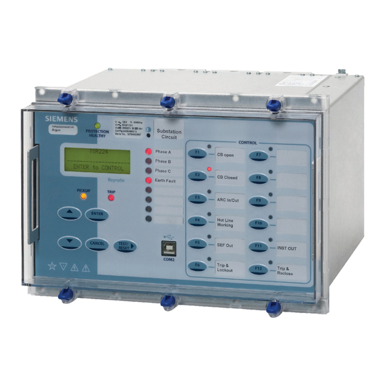
The operator interface is designed to provide a user-friendly method of controlling, entering settings and retrieving data from the relay. Figure 2.5-1 7SR224 with 12 Function Keys and 3 + 8 LEDs in E10 Case NOTE: Transparent cover with pushbuttons not shown The fascia is an integral part of the relay. - Page 13 7SR224 Argus Description of Operation Relay Information Above the LCD three labels are provided, these provide the following information: 1) Product name and order code. 2) Nominal current rating, rated frequency, voltage rating, auxiliary dc supply rating, binary input supply rating, configuration and serial number.
-
Page 14: Current Inputs
7SR224 Argus Description of Operation Standard Keys The relay is supplied as standard with five navigation / control pushbuttons and 12 programmable function keys. The navigation / control buttons are used to navigate the menu structure and control relay functions. They are labelled: ▲... -
Page 15: Figure 2.8-1 Binary Input Logic
7SR224 Argus Description of Operation Pick-up (PU) and drop-off (DO) time delays are associated with each binary input. Where no pick-up time delay has been applied the input may pick up due to induced ac voltage on the wiring connections (e.g. cross site wiring). -
Page 16: Binary Outputs (Output Relays)
7SR224 Argus Description of Operation Binary Outputs (Output Relays) Relays are fitted with 14, 22 or 30 binary outputs. All outputs are fully user configurable and can be programmed to operate from any or all of the available functions. The Power Supply module includes the relay basic I/O. The module includes six binary outputs each fitted with 1 contact –... -
Page 17: Virtual Input/Outputs
7SR224 Argus Description of Operation Figure 2.9-1 Binary Output Logic 2.10 Virtual Input/Outputs The relays have 16 virtual input/outputs, these are internal logic states. Virtual I/O is assigned in the same way as physical Binary Inputs and Binary Outputs. Virtual I/O is mapped from within the INPUT CONFIG > INPUT MATRIX and OUTPUT CONFIG >... -
Page 18: Battery And Capacitor Test Facility Of The Recloser
7SR224 Argus Description of Operation 2.12 Battery And Capacitor Test Facility Of The Recloser The quiescent battery voltage V is constantly monitored to ensure that the charging system is connected and operating correctly. The capacitor voltage is monitored externally by the Switch Unit Driver and Monitor. The healthy condition of the capacitor is indicated to the Controller by the state of two binary signals. -
Page 19: Section 3: Protection Functions
7SR224 Argus Description of Operation Section 3: Protection Functions Current Protection: Phase Overcurrent (67, 51, 50) All phase overcurrent elements have a common setting to measure either fundamental frequency RMS or True RMS current: True RMS current: 51/50 Measurement = RMS Fundamental Frequency RMS current: 51/50 Measurement = Fundamental 3.1.1 Directional Control of Overcurrent Protection (67) -
Page 20: Figure 3.1-1 Logic Diagram: Directional Overcurrent Element (67)
7SR224 Argus Description of Operation Minimum Polarising Voltage The 67 Minimum Voltage setting defines the minimum polarising voltage level. Where the measured polarising voltage is below this level no directional output is given and operation of protection elements set as directional will be inhibited. -
Page 21: Instantaneous Overcurrent Protection (50)
7SR224 Argus Description of Operation 3.1.2 Instantaneous Overcurrent Protection (50) Four elements are provided e.g. giving the option of using two elements set to forward and two to reverse. Each instantaneous element (50-n) has independent settings. 50-n Setting for pick-up current and 50-n Delay follower time delay. -
Page 22: Time Delayed Overcurrent Protection (51)
7SR224 Argus Description of Operation 3.1.3 Time Delayed Overcurrent Protection (51) Four elements are provided e.g. giving the option of using two elements set to forward and two to reverse. 51-n Setting sets the pick-up current level. Where the voltage controlled overcurrent function (51VCO) is used a multiplier is applied to this setting where the voltage drops below the setting VCO Setting, see section 3.2. -
Page 23: Figure 3.1-3 Logic Diagram: Time Delayed Overcurrent Element
7SR224 Argus Description of Operation See Voltage Controlled Overcurrent (51V) 51-n Element 51-n Setting Enabled 51-n Charact AUTORECLOSE Disabled & 51-n Time Mult 79 P/F Inst Trips = 51-n & 51-n Delay (DTL) 79 P/F Prot’n Trip n = Delayed 51-n Min. -
Page 24: Current Protection: Voltage Controlled Oc (51V)
7SR224 Argus Description of Operation Current Protection: Voltage Controlled OC (51V) Each shaped overcurrent element 51-n Setting can be independently controlled by the level of measured (control) input voltage. For applied voltages above VCO Setting the 51-n element operates in accordance with its normal current setting (see 3.1.3). -
Page 25: Current Protection: Measured Ef (67G, 51G, 50G)
7SR224 Argus Description of Operation Current Protection: Measured EF (67G, 51G, 50G) The earth current is measured directly via a dedicated current analogue input. All measured earth fault elements have a common setting to measure either fundamental frequency RMS, True... -
Page 26: Instantaneous Measured Earth Fault Protection (50G)
7SR224 Argus Description of Operation Figure 3.3-1 Logic Diagram: Measured Directional Earth Fault Protection 3.3.2 Instantaneous Measured Earth Fault Protection (50G) Four elements are provided e.g. giving the option of using two elements set to forward and two to reverse. -
Page 27: Time Delayed Measured Earth Fault Protection (51G)
7SR224 Argus Description of Operation 3.3.3 Time Delayed Measured Earth Fault Protection (51G) Four elements are provided e.g. giving the option of using two elements set to forward and two to reverse. 51G-n Setting sets the pick-up current level. A number of shaped characteristics are provided. An inverse definite minimum time (IDMT) characteristic is selected from IEC and ANSI curves using 51G-n Char. -
Page 28: Current Protection: Sensitive Ef (67Sef, 51Sef, 50Sef)
7SR224 Argus Description of Operation Current Protection: Sensitive EF (67SEF, 51SEF, 50SEF) Current for the Sensitive Earth Fault (SEF) elements is measured directly via a dedicated current analogue input. SEF elements measure the fundamental frequency RMS current. 3.4.1 Directional Control of Sensitive Earth Fault Protection (67SEF) The directional element produces forward and reverse outputs for use with SEF elements. -
Page 29: Instantaneous Sensitive Earth Fault Protection (50Sef)
7SR224 Argus Description of Operation 3.4.2 Instantaneous Sensitive Earth Fault Protection (50SEF) Four elements are provided e.g. giving the option of using two elements set to forward and two to reverse. Each instantaneous element has independent settings for pick-up current 50SEF-n Setting and a follower time delay 50SEF-n Delay. -
Page 30: Time Delayed Sensitive Earth Fault Protection (51Sef)
7SR224 Argus Description of Operation 3.4.3 Time Delayed Sensitive Earth Fault Protection (51SEF) Four elements are provided e.g. giving the option of using two elements set to forward and two to reverse. 51SEF-n Setting sets the pick-up current level. A number of shaped characteristics are provided. An inverse definite minimum time (IDMT) characteristic is selected from IEC and ANSI curves using 51SEF-n Char. -
Page 31: Current Protection: High Impedance Restricted Ef (64H)
7SR224 Argus Description of Operation Current Protection: High Impedance Restricted EF (64H) One high impedance Restricted Earth Fault (REF) element is provided. The relay utilises fundamental current measurement values for this function. The single phase current input is derived from the residual output of line/neutral CTs connected in parallel. An external stabilising resistor must be connected in series with this input to ensure that this element provides a high impedance path. -
Page 32: Current Protection: Cold Load (51C)
7SR224 Argus Description of Operation Current Protection: Cold Load (51c) The setting of each shaped overcurrent element (51-n) can be inhibited and alternative ‘cold load’ settings (51c-n) can be applied for a period following circuit switch in. The Cold Load settings are applied after the circuit breaker has been open for longer than the Pick-Up Time setting. -
Page 33: Current Protection: Negative Phase Seq. Oc (46Nps)
7SR224 Argus Description of Operation Current Protection: Negative Phase Seq. OC (46NPS) The negative sequence phase (NPS) component of current (I2) is derived from the three phase currents. It is a measure of the quantity of unbalanced current in the system. -
Page 34: Current Protection: Under-Current (37)
7SR224 Argus Description of Operation Current Protection: Under-Current (37) Two under-current elements are provided. Each phase has an independent level detector and current-timing element. 37-n Setting sets the pick-up current. An output is given after elapse of the 37-n Delay setting. -
Page 35: Current Protection: Thermal Overload (49)
7SR224 Argus Description of Operation Current Protection: Thermal Overload (49) The relay provides a thermal overload suitable for the protection of static plant. Phase segregated elements are provided. The temperature of the protected equipment is not measured directly. Instead, thermal overload conditions are calculated using the measure True RMS current. -
Page 36: Figure 3.9-1 Logic Diagram: Thermal Overload Protection (49S)
7SR224 Argus Description of Operation 49 Overload Setting 49 Therm. Overload 49 Time Constant Enabled 49 Capacity Alarm Disabled & Inhibit 49 cap alarm trip 49 Alarm cap alarm trip 49 Trip cap alarm trip Figure 3.9-1 Logic Diagram: Thermal Overload Protection (49S) ©2010 Siemens Protection Devices Limited... -
Page 37: Voltage Protection: Phase Under/Over Voltage (27/59)
7SR224 Argus Description of Operation 3.10 Voltage Protection: Phase Under/Over Voltage (27/59) In total five under/over voltage elements are provided. Four elements are provided for the ‘Phase’ Voltages and one for the ‘Auxiliary’ input voltage. The relay utilises fundamental frequency RMS voltage for this function. All under/over voltage elements have a common setting to measure phase to phase (Ph-Ph) or phase to neutral (Ph-N) voltage using the Voltage Input Mode setting. -
Page 38: Voltage Protection: Negative Phase Sequence Overvoltage (47)
7SR224 Argus Description of Operation 3.11 Voltage Protection: Negative Phase Sequence Overvoltage (47) Negative phase sequence (NPS) voltage (V2) is a measure of the quantity of unbalanced voltage in the system. The relay derives the NPS voltage from the three input voltages (VL1, VL2 and VL3). -
Page 39: Voltage Protection: Neutral Overvoltage (59N)
7SR224 Argus Description of Operation 3.12 Voltage Protection: Neutral Overvoltage (59N) Two Neutral Overvoltage (or Neutral Voltage Displacement) elements are provided. 59N Voltage Source setting selects the source of the residual voltage to be measured. The voltage is measured directly from the Vx input or derived from the line voltages where suitable VT connections are present. The relay utilises fundamental voltage measurement values for this function. -
Page 40: Voltage Protection: Under/Over Frequency (81)
7SR224 Argus Description of Operation 3.13 Voltage Protection: Under/Over Frequency (81) Four under/over frequency elements are provided. The relay utilises fundamental voltage measurement values for this function. The frequency calculation is based on the highest input voltage derived from the voltage selection algorithm. -
Page 41: Section 4: Control & Logic Functions
7SR224 Argus Description of Operation Section 4: Control & Logic Functions Autoreclose (79) 4.1.1 Overview A high proportion of faults on an Overhead Line (OHL) network are transient. These faults can be cleared and the network restored quickly by using Instantaneous (Fast) Protection trips followed by an automated sequence of CB reclosures after the line has been dead for a short time, this ‘deadtime’... - Page 42 7SR224 Argus Description of Operation Indications The Instruments Menu includes the following meters relevant to the status of the Autoreclose and Manual Closing of the circuit breaker: - Status of the AR sequence AR Shot Count. CB Open Countdown Timer...
-
Page 43: Autoreclose Sequences
7SR224 Argus Description of Operation 4.1.2 Autoreclose sequences The CONTROL & LOGIC>AUTORECLOSE PROT’N and CONTROL & LOGIC>AUTORECLOSE CONFIG’ menus, allow the user to set independent Protection and Autoreclose sequences for each type of fault i.e. Phase Fault (P/F), Earth Fault (E/F), Sensitive Earth Fault (SEF) or External Protections (EXTERN). Each Autoreclose sequence can be user set for up to four-shots i.e. -
Page 44: Autoreclose Prot'n Menu
7SR224 Argus Description of Operation 4.1.3 AUTORECLOSE PROT’N Menu This menu presents the Overcurrent Protection elements available for each type of Fault i.e. P/F, E/F or SEF and allows the user to select those that are to be applied as Inst trips; those that are to be applied as Delayed Trips;... - Page 45 7SR224 Argus Description of Operation 79 Check Synchronising during the Deadtime will start the Check Synchronising before the completion of the deadtime if the dead state of the line or bus becomes live during the deadtime. This restoration of Live voltage state indicates that the remote end circuit breaker has reclosed and therefore it is not necessary to delay the CB close until the deadtime expires.
-
Page 46: P/F Shots Sub-Menu
7SR224 Argus Description of Operation 4.1.5 P/F SHOTS sub-menu This menu allows the Phase fault trip/reclose sequence to be parameterized:- The first protection Trip in the P/F sequence can be set to either Inst or Delayed. 79 P/F Prot’n Trip1 Sets the first Reclose Delay (Dead time) in the P/F sequence. -
Page 47: Extern Shots Sub-Menu
7SR224 Argus Description of Operation 4.1.8 EXTERN SHOTS sub-menu This menu allows the External Protection autoreclose sequence to be parameterized:- Not Blocked/Blocked - Blocked raises an output which can be mapped to a Binary 79 P/F Prot’n Trip1 output to Block an External Protection’s Trip Output. -
Page 48: Figure 4.1-2 Basic Autoreclose Sequence Diagram
7SR224 Argus Description of Operation Figure 4.1-2 Basic Autoreclose Sequence Diagram ©2010 Siemens Protection Devices Limited Chapter 1 Page 46 of 70... -
Page 49: Manual Close
7SR224 Argus Description of Operation Manual Close A Manual Close Command can be initiated in one of four ways: via a Close CB binary input, via the data communication Channel(s), from the relay CONTROL MODE menu or from the relay fascia function keys. It causes an instantaneous operation via 79MC Close CB binary output, over-riding any autoreclose (AR) sequence in progress. -
Page 50: Charge Delays
7SR224 Argus Description of Operation 4.3.2 Charge Delays Separate delay settings are provided for Dead Line Charge and Dead Bus Charge closure. These are applied after the autoreclose Dead Time when voltage conditions are checked and met, at the Close Inhibit stage of the sequence. -
Page 51: Check Synchronising Mode
7SR224 Argus Description of Operation 4.3.5 Check Synchronising Mode The MOS On/Off input is provided to bypass the voltage and synchronising checks to provide an emergency close function. Similarly, check synchronising can be overridden by the 79 OS On/Off input during autoreclose. -
Page 52: System Sync Reversion
7SR224 Argus Description of Operation System Split condition is detected when either the measured phase difference angle exceeds the pre-set 25 Slip Angle value or if the slip frequency exceeds a pre-set 25 Split Slip rate based on the selection of 25 System Split Mode. -
Page 53: Close On Zero Mode
7SR224 Argus Description of Operation SLIP Slip Within Range ? Slip Frequency Setting Phase Within Range ? Φ Angle Phase Decreasing ? Slip Timer & SystemSync Phase Angle Setting Close Live Line Slip Timer & Setting Live Bus Line U/V... -
Page 54: Circuit Breaker
7SR224 Argus Description of Operation Circuit Breaker This menu includes relay settings applicable to both manual close (MC) and autoreclose (AR) functionality. CB Controls Latched CB controls for closing and tripping can be latched i.e. until confirmation that the action has been completed i.e. -
Page 55: Figure 4.4-1 Logic Diagram: Circuit Breaker Status
7SR224 Argus Description of Operation Hot Line In/Out When ‘Hot Line’ is enabled all autoreclose sequences are inhibited and any fault causes an instantaneous trip to lockout. Figure 4.4-1 Logic Diagram: Circuit Breaker Status ©2010 Siemens Protection Devices Limited Chapter 1 Page 53 of 70... -
Page 56: Quick Logic
7SR224 Argus Description of Operation Quick Logic The ‘Quick Logic’ feature allows the user to input up to 16 logic equations (E1 to E16) in text format. Equations can be entered using Reydisp or at the relay fascia. Each logic equation is built up from text representing control characters. Each can be up to 20 characters long. -
Page 57: Figure 4.5-1 Sequence Diagram: Quick Logic Pu/Do Timers (Counter Reset Mode Off)
7SR224 Argus Description of Operation Counter Equation n P.U. DELAY D.O. DELAY Counter En = 1 = Target Value Counter Value 1 Increment Counter Equation Output 1 For Counter Target = 2 En = 1 Figure 4.5-1 Sequence Diagram: Quick Logic PU/DO Timers (Counter Reset Mode Off) When the count value = En Counter Target the output of the counter (En) = 1 and this value is held until the initiating conditions are removed when En is instantaneously reset. -
Page 58: Section 5: Supervision Functions
7SR224 Argus Description of Operation Section 5: Supervision Functions Circuit Breaker Failure (50BF) The circuit breaker fail function has two time delayed outputs that can be used for combinations of re-tripping or back-tripping. CB Fail outputs are given after elapse of the 50BF-1 Delay or 50BF-2 Delay settings. -
Page 59: Vt Supervision (60Vts)
7SR224 Argus Description of Operation VT Supervision (60VTS) 1 or 2 Phase Failure Detection Normally the presence of negative phase sequence (NPS) or zero phase sequence (ZPS) voltage in a power system is accompanied by NPS or ZPS current. The presence of either of these sequence voltages without the equivalent level of the appropriate sequence current is used to indicate a failure of one or two VT phases. -
Page 60: Figure 5.2-1 Logic Diagram: Vt Supervision Function (60Vts)
7SR224 Argus Description of Operation Enabled Disabled & 60VTS Inhibit 1 or 2 Phase Fail Phase Seq. Filter & 60VTS Delay Phase Seq. & Filter > 1 3 Phase Fail 60VTS Operated & & >1 External Trigger 60VTS Ext_Trig External Reset 60VTS Ext_Reset Figure 5.2-1 Logic Diagram: VT Supervision Function (60VTS) -
Page 61: Busbar Vt Fail (60Vtf-Bus)
7SR224 Argus Description of Operation Busbar VT Fail (60VTF-Bus) When the optional synchronising function is fitted, the synchronising voltage transformer is utilised to provide an additional monitoring function to check the validity of the measured line and busbar voltages. When the circuit breaker is closed, both voltages should be either Live or Dead. -
Page 62: Broken Conductor (46Bc)
7SR224 Argus Description of Operation Broken Conductor (46BC) The element calculates the ratio of NPS to PPS currents. Where the NPS:PPS current ratio is above 46BC Setting an output is given after the 46BC Delay. The Broken Conductor function can be inhibited from A binary or virtual input. -
Page 63: Inrush Detector (81Hbl2)
7SR224 Argus Description of Operation Inrush Detector (81HBL2) Inrush restraint detector elements are provided, these monitor the line currents. The inrush restraint detector can be used to block the operation of selected elements during transformer magnetising inrush conditions. The 81HBL2 Bias setting allows the user to select between Phase, Sum and Cross methods of measurement: Each phase is inhibited separately. -
Page 64: Battery Test
7SR224 Argus Description of Operation Battery Test The DC battery voltage is constantly monitored by the relay. The output function Battery Healthy is provided to indicate that the battery charging system is connected and functioning correctly by measurement of the ‘Float Charge’... -
Page 65: Capacitor Test
7SR224 Argus Description of Operation Capacitor Test The actuator mechanism of the recloser can be driven from a charged capacitor network. The condition of the capacitors is monitored externally to the relay and the interface to the relay is in the form of two binary signals which are driven by undervoltage detectors as shown below. -
Page 66: Power Quality (27S/59S)
7SR224 Argus Description of Operation 5.10 Power Quality (27S/59S) Voltage sag (27S) and voltage swell (59S) elements monitor the power supply quality. The elements monitor the deviation of the voltage from the nominal value and the duration of this under or over voltage in accordance with IEEE 1159. -
Page 67: Section 6: Other Features
7SR224 Argus Description of Operation Section 6: Other Features Data Communications Two communication ports, COM1 and COM2 are provided. RS485 connections are available on the terminal blocks at the rear of the relay (COM1). A USB port, (COM 2), is provided at the front of the relay for local access using a PC. -
Page 68: Data Storage
7SR224 Argus Description of Operation Data Storage 6.4.1 General The relay stores three types of data: relay event records, analogue/digital waveform records and fault records. Data records are backed up in non-volatile memory and are permanently stored even in the event of loss of auxiliary d.c. -
Page 69: Fault Records
7SR224 Argus Description of Operation 6.4.4 Fault Records Up to ten fault records can be stored and displayed on the Fascia LCD. Fault records provide a summary of the relay status at the time of trip, i.e. the element that issued the trip, any elements that were picked up, the fault type, LED indications, date and time. -
Page 70: Operating Mode
7SR224 Argus Description of Operation Operating Mode The relay has three operating modes, Local, Remote and Out of Service. The following table identifies the functions operation in each mode. The modes can be selected by the following methods: SYSTEM CONFIG>RELAY MODE setting, a Binary Input or Command... -
Page 71: Real Time Clock
7SR224 Argus Description of Operation Set Local Mode Set Local or Remote Mode Set Remote Mode Set Service Mode Real Time Clock Time and date can be set either via the relay fascia using appropriate commands in the System Config menu, via the data comms channel(s) or via the optional IRIG-B input. -
Page 72: Password Feature
The password validation screen also displays a numerical code. If the password is lost or forgotten, this code should be communicated to Siemens Protection Devices Ltd. and the password can be retrieved. ©2010 Siemens Protection Devices Limited Chapter 1 Page 70 of 70... - Page 73 Limited. No part of this document shall be reproduced or modified or stored in another form, in any data retrieval system, without the permission of Siemens Protection Devices Limited, nor shall any model or article be reproduced from this document unless Siemens Protection Devices Limited consent.
- Page 74 List of Figures Figure 1.1-1 Menu ............................3 Figure 1.1-2 Fascia Contrast symbol .......................3 Figure 1.1-3 Fascia of a 7SR224 relay (Please note your model may differ from illustration)..........................4 Figure 1.2-4 Relay Identifier Screen ......................5 Figure 1.2-5 Typical Menu Structure (See Appendices for relevant software version)......6 Figure 2.1.1-1 USB connection to PC ......................9...
-
Page 75: Section 1: Introduction
7SR224 Argus Settings, Configuration & Instruments Section 1: Introduction Relay Menus And Display All relay fascias contain the same access keys although the fascias may differ in appearance from model to model. The basic menu structure is also the same in all products and consists of four main menus, these being, Settings Mode - allows the user to view and (if allowed via the settings mode password) change settings in the relay. - Page 76 7SR224 Argus Settings, Configuration & Instruments Figure 1.1-3 Fascia of a 7SR224 relay (Please note your model may differ from illustration) ©2010 Siemens Protection Devices Limited Chapter 2 Page 4 of 13...
-
Page 77: Operation Guide
7SR224 Argus Settings, Configuration & Instruments Operation Guide 1.2.1 User Interface Operation The basic menu structure flow diagram is shown in Figure 1.2-5. This diagram shows the main modes of display: Settings Mode, Instrument Mode, Fault Data Mode and Control Mode. - Page 78 7SR224 Argus Settings, Configuration & Instruments Figure 1.2-5 Typical Menu Structure (See Appendices for relevant software version) ©2010 Siemens Protection Devices Limited Chapter 2 Page 6 of 13...
-
Page 79: Settings Display
7SR224 Argus Settings, Configuration & Instruments Settings Display The Settings Mode is reached by pressing the READ DOWN ▼ button from the relay identifier screen. Once the Settings Mode title screen has been located pressing the READ DOWN ▼ button takes the user into the Settings mode sub-menus. -
Page 80: Instruments Mode
7SR224 Argus Settings, Configuration & Instruments Instruments Mode The Instrument Mode sub-menu displays key quantities and information to aid with commissioning. The following meters are available and are navigated around by using the READ UP ▲, READ DOWN ▼and TEST/REST buttons. -
Page 81: Section 2: Setting The Relay Using Reydisp Evolution
7SR224 Argus Settings, Configuration & Instruments Section 2: Setting the Relay Using Reydisp Evolution To set the relay using the communication port the user will need the following:- PC with Reydisp Evolution Installed. (This can be download from our website www.siemens.com/energy... -
Page 82: Rear Rs485 Connection
7SR224 Argus Settings, Configuration & Instruments 2.1.2 Rear RS485 connection Figure 2.1.2-1 RS485 connection to PC 2.1.3 Optional rear fibre optic connection Figure 2.1.3-1 Fibre Optic Connection to PC Sigma devices have a 25 pin female D connector with the following pin out. -
Page 83: Optional Rear Rs232 Connection
7SR224 Argus Settings, Configuration & Instruments 2.1.4 Optional Rear RS232 connection 9 pin Female D Connector Figure 2.1.4-1 Direct RS232 Connection to PC The optional RS232 port is a 9 pin male D connector with the following pin out. Function... - Page 84 7SR224 Argus Settings, Configuration & Instruments Setting name Range Default Units Notes Address given to relay to 1 – 254 for IEC60870-5- identify that relay from 103 or IEC60870-5-101 others which may be using Station Address the same path for 0 –...
-
Page 85: Connecting To The Relay Via Reydisp
7SR224 Argus Settings, Configuration & Instruments 2.1.6 Connecting to the Relay via Reydisp When Reydisp software is running all available communication ports of the PC will automatically be detected. On the start page tool bar open up the sub-menu File > Connect. - Page 86 Limited. No part of this document shall be reproduced or modified or stored in another form, in any data retrieval system, without the permission of Siemens Protection Devices Limited, nor shall any model or article be reproduced from this document unless Siemens Protection Devices Limited consent.
- Page 87 7SR224 Argus Performance Specification Contents Section 1: Common Functions ..........................5 1.1 General ..............................5 1.1.1 CE Conformity........................... 5 1.1.2 Reference ..........................5 1.1.3 Dimensions ..........................5 1.1.4 Weights ............................. 6 1.2 Energising Quantities ..........................7 1.2.1 Auxiliary Power Supply ......................7 1.2.2...
- Page 88 7SR224 Argus Performance Specification 2.8.3 Operate and Reset Time......................25 2.9 51 Time Delayed Overcurrent ....................... 26 2.9.1 Reference ..........................26 2.9.2 Operate and Reset Level ......................26 2.9.3 Operate and Reset Time......................27 2.10 51G Time Delayed Measured Earth Fault..................... 28 2.10.1...
- Page 89 7SR224 Argus Performance Specification Section 4: Control Functions ..........................47 4.1 Check Synchronising ..........................47 4.1.1 Reference ..........................47 4.1.2 Live/Dead Line/Bus Detector Elements .................. 47 4.1.3 Line and Bus Undervoltage Elements..................47 4.1.4 Voltage Difference ........................48 4.1.5 General Autoreclose Timers ....................48 4.1.6...
-
Page 90: Section 1: Common Functions
7SR224 Argus Performance Specification Section 1: Common Functions General 1.1.1 CE Conformity This product is CE compliant to relevant EU directives. 1.1.2 Reference This product complies with IEC 60255-3, IEC 60255-6 and IEC 60255-12. 1.1.2.1 Accuracy Reference Conditions This product has been tested under the following conditions, unless specifically stated otherwise. -
Page 91: Weights
7SR224 Argus Performance Specification 1.1.4 Weights Parameter Value 7SR2241, E10 case 5.98kg 7SR2242, E10 case 5.98kg 7SR2243, E10 case 5.98kg 7SR2244, E10 case 5.98kg Net weight 7SR2245, E10 case 5.98kg 7SR2246, E12 case 7.43kg 7SR2247, E12 case 7.80kg 7SR2248, E12 case 7.80kg... -
Page 92: Energising Quantities
7SR224 Argus Performance Specification Energising Quantities 1.2.1 Auxiliary Power Supply Nominal Operating Range 30, 48, 110, 220 VDC 24 to 290 VDC 1.2.1.1 Burden Attribute Value Quiescent (typical) 6.0 W 30V DC Quiescent (back light) 7.0 W Quiescent (typical) 5.5W... -
Page 93: Ac Voltage
7SR224 Argus Performance Specification 1.2.3 AC Voltage Nominal Operating Range 63.5V, 110 V 270 V 50, 60Hz 47 to 62Hz 1.2.3.1 Burden Attribute Value AC Burden ≤ 0.1 VA at 110 V 1.2.4 Binary (Digital) Outputs Contact rating to IEC 60255-0-2... -
Page 94: Binary (Digital) Inputs
7SR224 Argus Performance Specification 1.2.5 Binary (Digital) Inputs Nominal Operating Range 19 VDC 17 to 290 VDC 88 VDC 74 to 290 VDC 1.2.5.1 Performance Attribute Value = 19 V 1.5mA Maximum DC current for operation = 88 V 1.5mA ≥... - Page 95 7SR224 Argus Performance Specification ESI-1 ESI-2 30V DC Nominal 30V DC Nominal (24 – 37.5V Operative) (24 – 37.5V Operative) > 10mA > 20mA BI (19V) BI (19V) 48V DC Nominal 48V DC Nominal (37.5 – 60V Operative) (37.5 – 60V Operative) >...
-
Page 96: Functional Performance
7SR224 Argus Performance Specification Functional Performance 1.3.1 Instrumentation Instrument Value Reference Typical accuracy I ≥ 0.1 xIn ± 1 % In Current V ≥ 0.8 xVn ± 1 % Vn Voltage 1.3.2 USB Data Communication Interface Attribute Value Physical layer... - Page 97 7SR224 Argus Performance Specification 1.3.7.2 IRIG-B Attribute Value Connector Signal Type IRIG-B 120, 122 or 123 Applied signal level minimum 3 V, maximum 6 V, peak-to-peak ≥ 3 Signal : carrier ratio ©2010 Siemens Protection Devices Limited Chapter 3 Page 12 of 49...
-
Page 98: Environmental Performance
7SR224 Argus Performance Specification Environmental Performance 1.4.1 General 1.4.1.1 Temperature IEC 60068-2-1/2 Type Level -10 °C to +55 °C Operating range -25 °C to +70 °C Storage range 1.4.1.2 Humidity IEC 60068-2-3 Type Level 56 days at 40 °C and 95 % relative humidity Operational test 1.4.1.3... -
Page 99: Immunity
7SR224 Argus Performance Specification 1.4.3 Immunity 1.4.3.1 Auxiliary DC Supply Variation Quantity Value ≤ 12% of DC voltage Allowable superimposed ac component Allowable breaks/dips in supply ≤ 20ms (collapse to zero from nominal voltage) 1.4.3.2 High Frequency Disturbance IEC 60255-22-1 Class III... -
Page 100: Mechanical
7SR224 Argus Performance Specification 1.4.4 Mechanical 1.4.4.1 Vibration (Sinusoidal) IEC 60255-21-1 Class I Type Level Variation Vibration response 0.5 gn ≤ 5 % Vibration endurance 1.0 gn 1.4.4.2 Shock and Bump IEC 60255-21-2 Class I Type Level Variation Shock response... -
Page 101: Section 2: Protection Functions
7SR224 Argus Performance Specification Section 2: Protection Functions 27/59 Under/Over Voltage 2.1.2 Reference Parameter Value Setting 5, 5.5…200V hyst Hysteresis setting 0, 0.1… 80.0% 0.00, 0.01…20.00, 20.50… 100, 101… 1000, 1010… Delay setting 10000, 10100… 14400 s 2.1.3 Operate and Reset Level... -
Page 102: Undercurrent
7SR224 Argus Performance Specification 37 Undercurrent 2.2.2 Reference Parameter Value Setting 0.05, 0.10…5.0 xIn 0.00, 0.01…20.00, 20.50… 100, 101… 1000, 1010… Delay setting 10000, 10100… 14400 s 2.2.3 Operate and Reset Level Attribute Value 100 % Is, ± 5 % or ± 1% In... -
Page 103: 46Nps Negative Phase Sequence Overcurrent
7SR224 Argus Performance Specification 46NPS Negative Phase Sequence Overcurrent 2.3.1 Reference (46DT) Parameter Value Setting 0.05, 0.06... 4.0xIn 0.00, 0.01…20.00, 20.50… 100, 101… 1000, 1010… Delay setting 10000, 10100… 14400 s 2.3.2 Operate and Reset Level (46DT) Attribute Value 100 % Is, ± 5 % or ± 1% In Operate level ≥... -
Page 104: Reference (46It)
7SR224 Argus Performance Specification 2.3.4 Reference (46IT) Parameter Value char Characteristic setting IEC-NI, -VI, -EI, -LTI; ANSI-MI, -VI, -EI; DTL Time Multiplier setting 0.025, 0.050 … 1.6 Setting 0.05, 0.06… 2.5xIn Applied Current (for operate time) 2 to 20 x Is... -
Page 105: Negative Phase Sequence Voltage
7SR224 Argus Performance Specification 47 Negative Phase Sequence Voltage 2.4.1 Reference (47) Parameter Value Setting 1, 1.5… 90V Hyst. Hysteresis 0, 0.1… 80% 0.00, 0.01…20.00, 20.50… 100, 101… 1000, 1010… 10000, Delay setting 10100… 14400 s 2.4.2 Operate and Reset Level (47) -
Page 106: Thermal Overload
7SR224 Argus Performance Specification 49 Thermal Overload 2.5.1 Reference Parameter Value Overload setting 0.10, 0.11… 3 xIn τ Time constant setting 1, 1.5… 1000 min 2.5.2 Operate and Reset Level Attribute Value 100 % Is, ± 5 % or ± 1% In Overload level ≥... - Page 107 7SR224 Argus Performance Specification 100000 10000 τ = 1000 mins 1000 Time (sec) τ = 100 mins τ = 10 mins τ = 1 min Current (multiple of setting) Figure 2-1 Thermal Overload Protection Curves ©2010 Siemens Protection Devices Limited...
-
Page 108: Instantaneous Overcurrent
7SR224 Argus Performance Specification 50 Instantaneous Overcurrent 2.6.1 Reference Parameter Value Setting 0.05, 0.06 …2, 2.05… 25, 25.5… 50 xIn Applied Current (for operate time) 5 xIs 0.00, 0.01…20.00, 20.50… 100, 101… 1000, 1010… Delay setting 10000, 10100… 14400 s 2.6.2... -
Page 109: Instantaneous Measured Earth Fault
7SR224 Argus Performance Specification 50G Instantaneous Measured Earth Fault 2.7.1 Reference Parameter Value Setting 0.005, 0.006 …0.1, 0.105 .. 2.5, 2.55 … 25 xIn Applied Current (for operate time) 5 x Is 0.00, 0.01…20.00, 20.50… 100, 101… 1000, 1010… Delay setting 10000, 10100…... -
Page 110: 50Sef Instantaneous Sensitive Earth Fault
7SR224 Argus Performance Specification 50SEF Instantaneous Sensitive Earth Fault 2.8.1 Reference Parameter Value Setting 0.005, 0.006 …0.1, 0.105 .. 5 xIn 0.00, 0.01… 20.0, 20.1 .. 100.0, 101.…1000, 1010 … Delay setting 10000 , 10100 … 14400 Applied current (for operate time) 5 xIs 2.8.2... -
Page 111: Time Delayed Overcurrent
7SR224 Argus Performance Specification 51 Time Delayed Overcurrent 2.9.1 Reference Parameter Value Setting 0.05, 0.06… 2.5 xIn IEC-NI, -VI, -EI, -LTI; ANSI-MI, -VI, -EI; DTL char Characteristic setting Manufacturer specific curves See ‘Performance Specification Appendix 1’ Time Multiplier setting 0.025, 0.05… 1.6... -
Page 112: Operate And Reset Time
7SR224 Argus Performance Specification 2.9.3 Operate and Reset Time Attribute Value 20 ms, ± 20ms Starter operate time (≥ 2xIs) × , ± 5 % absolute or ± 30 ms, α − char = IEC-NI, IEC-VI, IEC-NI : K = 0.14, α = 0.02... -
Page 113: Time Delayed Measured Earth Fault
7SR224 Argus Performance Specification 2.10 51G Time Delayed Measured Earth Fault 2.10.1 Reference Parameter Value Setting 0.005, 0.006 …0.100, 0.105… 1.0 xIn IEC-NI, -VI, -EI, -LTI; ANSI-MI, -VI, -EI; DTL Char Characteristic setting Manufacturer specific curves See ‘Performance Specification Appendix 1’... -
Page 114: Operate And Reset Time
7SR224 Argus Performance Specification 2.10.3 Operate and Reset Time Attribute Value 20 ms, ± 20ms Starter operate time (≥ 2xIs) × , ± 5 % absolute or ± 30 ms, α − char = IEC-NI, IEC-VI, IEC-NI : K = 0.14, α = 0.02... - Page 115 7SR224 Argus Performance Specification 1000 Time (sec) Long Time Inverse Normal Inverse Very Inverse Extremely Inverse 50 60 Current (multiples of setting) Figure 2-2 IEC IDMTL Curves (Time Multiplier=1) ©2010 Siemens Protection Devices Limited Chapter 3 Page 30 of 49...
- Page 116 7SR224 Argus Performance Specification 1000 Time (sec) Moderately Inverse Very Inverse Extremely Inverse 50 60 Current (multiples of setting) Figure 2-3 ANSI IDMTL Operate Curves (Time Multiplier=1) ©2010 Siemens Protection Devices Limited Chapter 3 Page 31 of 49...
- Page 117 7SR224 Argus Performance Specification 1000 Extremely Inverse Very Inverse Time (sec) Moderately Inverse 0.8 0.9 Current (multiples of setting) Figure 2-4 ANSI Reset Curves (Time Multiplier=1) ©2010 Siemens Protection Devices Limited Chapter 3 Page 32 of 49...
-
Page 118: 51Sef Time Delayed Sensitive Earth Fault
7SR224 Argus Performance Specification 2.11 51SEF Time Delayed Sensitive Earth Fault 2.11.1 Reference Parameter Value Setting 0.005, 0.006 …0.100, 0.105… 1.0 xIn IEC-NI, -VI, -EI, -LTI; ANSI-MI, -VI, -EI; DTL char Characteristic setting Manufacturer specific curves See ‘Performance Specification Appendix 1’... -
Page 119: Operate And Reset Time
7SR224 Argus Performance Specification 2.11.3 Operate and Reset Time Attribute Value 20 ms, ± 20ms Starter operate time × , ± 5 % absolute or ± 30 ms, α − char = IEC-NI, IEC-VI, IEC-NI : K = 0.14, α = 0.02... -
Page 120: Voltage Controlled Overcurrent
7SR224 Argus Performance Specification 2.12 51V Voltage Controlled Overcurrent 2.12.1 Reference Parameter Value Setting multiplier Setting 1xIn 2.12.2 Operate and Reset Level Attribute Value 100 % Vs, ± 1 % or ± 0.25V Operate level ≤ 105 % V Reset level ±... -
Page 121: Neutral Voltage Displacement
7SR224 Argus Performance Specification 2.13 59N Neutral Voltage Displacement 2.13.1 Reference (59NDT) Parameter Value Setting 1, 1.5… 100V 0.00, 0.01…20.00, 20.50… 100, 101… 1000, 1010… 10000, Delay setting 10100… 14400 s 2.13.2 Operate and Reset Level (59NDT) Attribute Value 100 % Vs, ± 2 % or ± 0.5 V Operate level ≥... -
Page 122: Operate And Reset Time (59Nit)
7SR224 Argus Performance Specification 2.13.6 Operate and Reset Time (59NIT) Attribute Value 65 ms, ± 20ms Starter operate time (≥ 2xVs) basic , ± 5 % or ± 65 ms − char = IDMTL Operate time , ± 1 % or ± 40ms char = DTL , ±... -
Page 123: Restricted Earth Fault Protection
7SR224 Argus Performance Specification 2.14 64H Restricted Earth Fault Protection 2.14.1 Reference Parameter Value Setting 0.005, 0.006 ..0.100, 0.105… 0.95 xIn 0.00, 0.01… 20.0, 20.1… 100.0, 101.…1000, 1010 … Delay setting 10000 , 10100 … 14400 s 2.14.2 Operate and Reset Level... -
Page 124: 67/67G/67Sef Directional Overcurrent & Earth Fault
7SR224 Argus Performance Specification 2.15 67/67G/67SEF Directional Overcurrent & Earth Fault 2.15.1 Reference Parameter Value -95…+95 ° θ Angle setting Applied current Applied voltage 110 V phase-phase (63.5 V phase-earth) Setting (V0) 0.33, 0.5, 1.0 … 67V 2.15.2 Operate Angle... -
Page 125: 81Under/Over Frequency
7SR224 Argus Performance Specification 2.16 81Under/Over Frequency 2.16.1 Reference Parameter Value Setting 40, 40.01… 69.99 Hz Hyst Hysteresis setting 0, 0.1… 80% 0.00, 0.01… 20.0, 20.5… 100.0, 101.…1000, 1010 … 10000 , Delay setting 10100 … 14400 s 2.16.2 Operate and Reset Level... -
Page 126: Section 3: Supervision Functions
7SR224 Argus Performance Specification Section 3: Supervision Functions 46BC Broken Conductor 3.1.1 Reference Parameter Value NPS to PPS ratio 20…100% Delay setting 0.02…1000 s 3.1.2 Operate and Reset Level Attribute Value ± 5 % Operate level 100 % I curr ±... -
Page 127: 50Bf Circuit Breaker Fail
7SR224 Argus Performance Specification 50BF Circuit Breaker Fail 3.2.1 Reference Parameter Value Setting 0.005, 0.010… 2.0 xIn Stage 1 Delay setting 0, 2, 0.205… 60000ms CBF1 Stage 2 Delay setting 0, 2, 0.205… 60000ms CBF2 3.2.2 Operate and Reset Level... -
Page 128: 60Cts Current Transformer Supervision
7SR224 Argus Performance Specification 60CTS Current Transformer Supervision 3.3.1 Reference Parameter Value Current Threshold 0.05, 0.1… 1 xIn thresh Voltage Threshold 7, 8… 110V thresh 0.00, 0.01…20.00, 20.50… 100, 101… 1000, 1010… Delay setting 10000, 10100… 14400 s 3.3.2 Current & Voltage Threshold... -
Page 129: 60Vts Voltage Transformer Supervision
7SR224 Argus Performance Specification 60VTS Voltage Transformer Supervision 3.4.1 Reference (60VTS) Parameter Value Vnps Level 7, 8 … 110V Inps Level 0.05, 0.1 … 1 x In Ipps Load Level 0.05, 0.1 … 1 x In Ipps Fault Level 0.05, 0.1 … 20 x In Vpps Level 1, 2 …... -
Page 130: 60Vtf-Bus Voltage Transformer Supervision
7SR224 Argus Performance Specification 60VTF-B Voltage Transformer Supervision 3.5.1 Reference (60VTF) Parameter Value Operate time 0.1, 0.2 … 100s 3.5.2 Operate and Reset Time Attribute Value 30 ms ± 20ms Basic operate time basic , ± 1 % or ± 10ms... -
Page 131: 81Hbl2 Inrush Detector
7SR224 Argus Performance Specification 81HBL2 Inrush Detector 3.7.1 Reference Parameter Value Setting (Ratio of 2nd Harmonic current to 0.10, 0.11... 0.5 Fundamental component current) 3.7.2 Operate and Reset Level Attribute Value 100 % I, ± 4 % or ± 1% In Operate level , ±... -
Page 132: Section 4: Control Functions
7SR224 Argus Performance Specification Section 4: Control Functions Check Synchronising 4.1.1 Reference Parameter Value Nominal Voltage 40-160V Nominal Frequency 50/60Hz Live Setting 10% - 150% live Dead Setting 10% - 150% dead Line Voltage Setting 10% - 150% Bus Voltage Setting... -
Page 133: Voltage Difference
7SR224 Argus Performance Specification 4.1.4 Voltage Difference Attribute Value , ± 1 % V Operate level 100 % V diff ≥ V Reset level – 4% ± 2 % Repeatability 4.1.5 General Autoreclose Timers Attribute Value Element basic operate time 20ms ±20ms... -
Page 134: Loss Of Voltage (Lov) Loop Automation Function
7SR224 Argus Performance Specification Loss of Voltage (LOV) Loop Automation Function 4.2.1 Reference (LOV-A/X Dead/Live ) Parameter Value Live Vs Setting 5, 5.5… 80V Dead Vs Setting 5, 5.5… 80V 4.2.2 Operate and Reset Level Attribute Value 100 % LiveVs, ± 2 % or ± 0.5 V Operate level 100 % DeadVs, ±... - Page 135 Limited. No part of this document shall be reproduced or modified or stored in another form, in any data retrieval system, without the permission of Siemens Protection Devices Limited, nor shall any model or article be reproduced from this document unless Siemens Protection Devices Limited consent.
- Page 136 7SR224 Argus Data Comms Contents Section 1: Introduction ............................. 3 Section 2: Physical Connection..........................4 2.1 Communication Ports..........................4 2.1.1 DNP 3.0 Settings ........................4 2.1.2 IEC60870-5-101 Settings......................5 2.1.3 USB Interface..........................6 2.1.4 RS485 Interface ........................7 2.1.5 Fibre Optic Interface ......................... 8 Section 3: IEC 60870-5-103 Definitions .........................
-
Page 137: Section 1: Introduction
This section specifies connection details and lists the events, commands and measurands available. For further information regarding the IEC60870-5-103 interface, reference should be made to the separate Informative Communications Interface manual (reference 434/TM/5 available from www.siemens.com/energy). The Communications Interface for dialogue communications by the Protection Engineer is provided by the Reydisp Evolution software package, also available from the website, using the IEC60870-5-103 protocol. -
Page 138: Section 2: Physical Connection
Any or all ports can be mapped to the IEC60870-5-103, DNP3, MODBUS RTU or IEC60870-5-101 protocol at any one time, protocols available will depend upon relay model. Siemens Protection Devices Limited can provide a range of interface devices, please refer to product portfolio catalogue. -
Page 139: Iec60870-5-101 Settings
7SR224 Argus Data Comms 2.1.2 IEC60870-5-101 Settings The following relay settings are provided for configuration of the IEC60870-5-101 implementation when available and are common to all ports using this protocol. Setting name Range Default Setting Notes Balanced transmission is used for point to point connection to one device. -
Page 140: Usb Interface
7SR224 Argus Data Comms Setting name Range Default Setting Notes Period device will generate background data. Set to Off to disable generating of background I101 Background Off, 1 ..1500 minutes As Required data. Only data points Period with the background flag set will be generated in the background. -
Page 141: Rs485 Interface
7SR224 Argus Data Comms 2.1.4 RS485 Interface An RS485 communication port is located on the rear of the relay and can be connected using a suitable RS485 120 ohm screened twisted pair cable. The RS485 electrical connection can be used in a single or multi-drop configuration. The RS485 master must support and use the Auto Device Enable (ADE) feature. -
Page 142: Fibre Optic Interface
7SR224 Argus Data Comms 2.1.5 Fibre Optic Interface When connecting via the optional fibre optic interface the selection of fibre-optic cable is important. Fibres must be terminated with ST (BFOC/2.5) connectors. The recommended type is 62.5/125µm glass fibre. Communication distances over 1 km are achievable using this type of fibre. - Page 143 7SR224 Argus Data Comms Loss per connector Total loss at connectors (IxJ) Total losses (E+H+K) Receive power budget (A-L) Safety Margin Device Receive Sensitivity There are two optional fibre optic ports, com3 and com4, and when fitted the associated settings are available in the Data Communication menu.
- Page 144 7SR224 Argus Data Comms Setting name Range Default Setting Notes The parity set on all of the relays connected to the same fibre optic system NONE, ODD, EVEN EVEN As Required COM4 Parity must be the same and in accordance with the master device.
- Page 145 7SR224 Argus Data Comms Figure 2-4 Communication to Multiple Devices from Control System and Laptop using Fibre-optic Star Network ©2010 Siemens Protection Devices Limited Chapter 4 Page 11 of 76...
-
Page 146: Section 3: Iec 60870-5-103 Definitions
7SR224 Argus Data Comms Section 3: IEC 60870-5-103 Definitions Introduction This section describes the IEC 60870-5-103 protocol implementation in the relays. This protocol is used for the communication with Reydisp software and can also be used for communication with a suitable control system. - Page 147 7SR224 Argus Data Comms Information Number and Function The following table lists information number and function definitions together with a description of the message and function type and cause of transmission that can result in that message. Definitions with shaded area are not available on all relay models.
- Page 148 7SR224 Argus Data Comms Information Function Function Description Cause of Transmission Number Type SE, GI, General Alarm 7 SE, GI, General Alarm 8 SE, GI, General Alarm 9 SE, GI, General Alarm 10 SE, GI, General Alarm 11 SE, GI,...
- Page 149 7SR224 Argus Data Comms Information Function Function Description Cause of Transmission Number Type Binary Input 21 SE, GI, Binary Input 22 SE, GI, Binary Input 23 SE, GI, Binary Input 24 SE, GI, Binary Input 25 SE, GI, Binary Input 26...
- Page 150 7SR224 Argus Data Comms Information Function Function Description Cause of Transmission Number Type SE, GI, Binary Output 4 Ack, Nak SE, GI, Binary Output 5 Ack, Nak SE, GI, Binary Output 6 Ack, Nak SE, GI, Binary Output 7 Ack, Nak...
- Page 151 7SR224 Argus Data Comms Information Function Function Description Cause of Transmission Number Type SE, GI, Binary Output 29 Ack, Nak SE, GI, Binary Output 30 Ack, Nak SE, GI, Binary Output 31 Ack, Nak SE, GI, Binary Output 32 Ack, Nak...
- Page 152 7SR224 Argus Data Comms Information Function Function Description Cause of Transmission Number Type Trip In>> CB on by auto reclose SE, GI Data Lost 51-1 SE, GI 50-1 SE, GI 51G-1 SE, GI 50G-1 SE, GI 51-2 SE, GI 50-2...
- Page 153 7SR224 Argus Data Comms Information Function Function Description Cause of Transmission Number Type 59NDT SE, GI Vx27/59 SE, GI 81-1 SE, GI 81-2 SE, GI 81-3 SE, GI 81-4 SE, GI Trip Circuit Fail 1 SE, GI Trip Circuit Fail 2...
- Page 154 7SR224 Argus Data Comms Information Function Function Description Cause of Transmission Number Type SEF Inst Protection Inhibited SE, GI Ext Inst Protection Inhibited SE, GI LOV Primed SE, GI LOV Trip SE, GI LOV Close SE, GI LOV Inhibit Fast Protection...
- Page 155 7SR224 Argus Data Comms Information Function Function Description Cause of Transmission Number Type CB LO Handle Ops Count SE, GI 25 Check Sync SE, GI 25 System Sync SE, GI 25 Close On Zero SE, GI 25 System Split SE, GI...
- Page 156 7SR224 Argus Data Comms Information Function Function Description Cause of Transmission Number Type CB-A 79 AR In progress SE, GI CB-A Frequent Ops Count SE, GI Reset CB-A Frequent Ops Count Ack, Nak CB-A LO Handle Ops Count SE, GI...
- Page 157 7SR224 Argus Data Comms Information Function Function Description Cause of Transmission Number Type Cap-B Test Fail Cap-B Recovery Fail Cap-B Test SE, GI CB-B Deadtime Running SE, GI Close CB-C Failed Open CB-C Failed CB-C Reclaim SE, GI CB-C Lockout...
- Page 158 7SR224 Argus Data Comms Information Function Function Description Cause of Transmission Number Type Ack, Nak CB 1 Trip & Lockout Ack, Nak SE, GI Mode A - 3PTrip3PLO Ack, Nak SE, GI Mode B - 1PTrip3PLO Ack, Nak SE, GI...
- Page 159 7SR224 Argus Data Comms Disturbance Recorder Actual Channel (ACC) Numbers Function ACC Number Description Global Not Used V1, V2 and V3 are dependent on Phase Voltage Config setting and represent Van, Vbn, Vcn or Vab, Vbc, V0 or Va, Vb, Vc ©2010 Siemens Protection Devices Limited...
-
Page 160: Section 4: Modbus Definitions
7SR224 Argus Data Comms Section 4: Modbus Definitions Introduction This section describes the MODBUS-RTU protocol implementation in the relays. This protocol is used for communication with a suitable control system. This protocol can be set to use the Fibre Optic, RS232 and RS485 ports. The relay can communicate simultaneously on all ports regardless of protocol used. - Page 161 7SR224 Argus Data Comms Address Description 00110 CB 1 Trip & Reclose (Write only location) 00111 CB 1 Trip & Lockout (Write only location) 00112 Auto-reclose on/off 00113 Hot Line Working on/off 00114 E/F off/on 00115 SEF off/on 00116 Inst Protection off/on...
- Page 162 7SR224 Argus Data Comms Inputs (Read Only Binary values) Address Description 10001 Binary Input 1 10002 Binary Input 2 10003 Binary Input 3 10004 Binary Input 4 10005 Binary Input 5 10006 Binary Input 6 10007 Binary Input 7 10008...
- Page 163 7SR224 Argus Data Comms Address Description 10119 Start/Pick Up N 10120 Fault Forward/Line 10121 Fault Reverse/Busbar 10122 51-1 10123 50-1 10126 51G-1 10127 50G-1 10128 51-2 10129 50-2 10132 51G-2 10133 50G-2 10134 51-3 10135 50-3 10138 51G-3 10139 50G-3...
- Page 164 7SR224 Argus Data Comms Address Description 10192 Battery Volts Low 10193 Battery Volts High 10194 Battery Healthy 10195 Battery Recovery Fail 10196 Battery Test 10197 Capacitor Ready 10198 Capacitor Test Pass 10199 Capacitor Test Fail 10200 Capacitor Recovery Fail 10201...
- Page 165 7SR224 Argus Data Comms Address Description 10252 Cap-B Ready 10253 Cap-B Test Pass 10254 Cap-B Test Fail 10255 Cap-B Recovery Fail 10256 Cap-B Test 10257 CB-B Open 10258 CB-B Closed 10259 CB-C Reclaim 10260 CB-C Lockout 10261 CB-C Total Trip Count...
- Page 166 7SR224 Argus Data Comms Address Description 10341 LOV B Live 10342 LOV C Live 10343 LOV X Live 10344 LOV Y Live 10345 LOV Z Live 10346 LOV A 10347 LOV B 10348 LOV C 10349 LOV X 10350 LOV Y...
- Page 167 7SR224 Argus Data Comms Address Name Format Description 30082 Phase A Nominal FP_32BITS_3DP Ia Degrees 30084 Phase B Nominal FP_32BITS_3DP Ib Degrees 30086 Phase C Nominal FP_32BITS_3DP Ic Degrees 30088 In Primary FP_32BITS_3DP IN kA 30090 In Secondary FP_32BITS_3DP IN A...
-
Page 168: Event Format
7SR224 Argus Data Comms Address Name Format Description 30231 Vyz Primary FP_32BITS_3DP Vyz kV 30233 Vzx Primary FP_32BITS_3DP Vzx kV 30241 CB Total Trip Count UINT32 CB Total Trip Count 30243 CB Delta Trip Count UINT32 CB Delta Trip Count... -
Page 169: Section 5: Dnp3.0 Definitions
DEVICE PROFILE DOCUMENT (Also see the DNP 3.0 Implementation Table Section 5.2.) Vendor Name: Siemens Protection Devices Ltd. Device Name: 7SR224 , using the Triangle MicroWorks, Inc. DNP3 Slave Source Code Library, Version Highest DNP Level Supported: Device Function: For Requests:... - Page 170 7SR224 Argus Data Comms DNP V3.0 DEVICE PROFILE DOCUMENT (Also see the DNP 3.0 Implementation Table Section 5.2.) Timeouts while waiting for: Data Link Confirm: None Fixed at 2sec Variable Configurable. Complete Appl. Fragment: Fixed at ____ Variable Configurable None...
- Page 171 7SR224 Argus Data Comms DNP V3.0 DEVICE PROFILE DOCUMENT (Also see the DNP 3.0 Implementation Table Section 5.2.) Sends Multi-Fragment Responses: Configurable Sequential File Transfer Support: File Transfer Support Append File Mode Custom Status Code Strings Permissions Field File Events Assigned to Class...
- Page 172 7SR224 Argus Data Comms Implementation Table The following table identifies which object variations, function codes, and qualifiers the Triangle MicroWorks, Inc. DNP 3.0 Slave Source Code Library supports in both request messages and in response messages. For static (non-change-event) objects, requests sent with qualifiers 00, 01, 06, 07, or 08, will be responded with qualifiers 00 or 01.
- Page 173 7SR224 Argus Data Comms REQUEST RESPONSE OBJECT (Library will parse) (Library will respond with) Function Object Variation Qualifier Function Qualifier Description Codes Number Number Codes (hex) Codes (dec) Codes (hex) (dec) Binary Output Status 00, 01 00, 01 (read) (start-stop)
- Page 174 7SR224 Argus Data Comms REQUEST RESPONSE OBJECT (Library will parse) (Library will respond with) Function Object Variation Qualifier Function Qualifier Description Codes Number Number Codes (hex) Codes (dec) Codes (hex) (dec) 16-Bit Analog Input 00, 01 00, 01 (read) (start-stop)
- Page 175 7SR224 Argus Data Comms REQUEST RESPONSE OBJECT (Library will parse) (Library will respond with) Function Object Variation Qualifier Function Qualifier Description Codes Number Number Codes (hex) Codes (dec) Codes (hex) (dec) long floating point Analog Change 17, 28 (read) (no range, or all)
- Page 176 7SR224 Argus Data Comms REQUEST RESPONSE OBJECT (Library will parse) (Library will respond with) Function Object Variation Qualifier Function Qualifier Description Codes Number Number Codes (hex) Codes (dec) Codes (hex) (dec) (enbl. (no range, or all) unsol.) (dab. unsol.) (assign...
-
Page 177: Point List
7SR224 Argus Data Comms Point List The tables below identify all the default data points provided by the implementation of the Triangle MicroWorks, Inc. DNP 3.0 Slave Source Code Library. Note, not all points listed here apply to all builds of devices. - Page 178 7SR224 Argus Data Comms Binary Input Points Static (Steady-State) Object Number: 1 Change Event Object Number: 2 Default Static Variation reported when variation 0 requested: 2 (Binary Input with flags) Default Change Event Variation reported when variation 0 requested: 2 (Binary Input with absolute time)
- Page 179 7SR224 Argus Data Comms Binary Input Points Static (Steady-State) Object Number: 1 Change Event Object Number: 2 Default Static Variation reported when variation 0 requested: 2 (Binary Input with flags) Default Change Event Variation reported when variation 0 requested: 2 (Binary Input with absolute time)
- Page 180 7SR224 Argus Data Comms Binary Input Points Static (Steady-State) Object Number: 1 Change Event Object Number: 2 Default Static Variation reported when variation 0 requested: 2 (Binary Input with flags) Default Change Event Variation reported when variation 0 requested: 2 (Binary Input with absolute time)
- Page 181 7SR224 Argus Data Comms Binary Input Points Static (Steady-State) Object Number: 1 Change Event Object Number: 2 Default Static Variation reported when variation 0 requested: 2 (Binary Input with flags) Default Change Event Variation reported when variation 0 requested: 2 (Binary Input with absolute time)
- Page 182 7SR224 Argus Data Comms Binary Input Points Static (Steady-State) Object Number: 1 Change Event Object Number: 2 Default Static Variation reported when variation 0 requested: 2 (Binary Input with flags) Default Change Event Variation reported when variation 0 requested: 2 (Binary Input with absolute time)
- Page 183 7SR224 Argus Data Comms Binary Output Status Points and Control Relay Output Blocks The following table lists both the Binary Output Status Points (Object 10) and the Control Relay Output Blocks (Object 12). While Binary Output Status Points are included here for completeness, they are not often polled by DNP 3.0 Masters.
- Page 184 7SR224 Argus Data Comms Binary Output Status Points Static Object Number: 10 Change Event Object Number: 11 Default Variation reported when variation 0 requested: 2 (Binary Output with flags) Default Change Event variation 0 requested: 2 (Binary Output absolute time)
- Page 185 7SR224 Argus Data Comms Binary Output Status Points Static Object Number: 10 Change Event Object Number: 11 Default Variation reported when variation 0 requested: 2 (Binary Output with flags) Default Change Event variation 0 requested: 2 (Binary Output absolute time)
- Page 186 7SR224 Argus Data Comms Analogue Inputs The following table lists Analogue Inputs (Object 30). It is important to note that 16-bit and 32-bit variations of Analogue Inputs, Analogue Output Control Blocks, and Analogue Output Statuses are transmitted through DNP as signed numbers.
- Page 187 7SR224 Argus Data Comms Analog Inputs Static (Steady-State) Object Number: 30 Change Event Object Number: 32 Default Static Variation reported when variation 0 requested: 2 (16-Bit Analog Input with Flag) Default Change Event Variation reported when variation 0 requested: 4 (16-Bit Analog Change Event with Time) Def.
- Page 188 7SR224 Argus Data Comms Analog Inputs Static (Steady-State) Object Number: 30 Change Event Object Number: 32 Default Static Variation reported when variation 0 requested: 2 (16-Bit Analog Input with Flag) Default Change Event Variation reported when variation 0 requested: 4 (16-Bit Analog Change Event with Time) Def.
-
Page 189: Iec60870-5-101 Introduction
7SR224 Argus Data Comms IEC60870-5-101 Introduction This section describes the IEC 60870-5-101 protocol implementation in the relays. The control system or local PC acts as the master in the system with the relay operating as a slave responding to the master’s commands. - Page 190 7SR224 Argus Data Comms <32> M_ST_TB_1 <33> M_BO_TB_1 <34> M_ME_TD_1 <35> M_ME_TE_1 <36> M_ME_TF_1 <37> M_IT_TB_1 <38> M_EP_TD_1 <39> M_EP_TE_1 <40> M_EP_TF_1 <45> C_SC_NA_1 <46> C_DC_NA_1 <47> C_RC_NA_1 <70> M_EI_NA_1 <100> C_IC_NA_1 <101> C_CI_NA_1 <102> C_RD_NA_1 <103> C_CS_NA_1 <104> C_TS_NA_1 <105>...
- Page 191 7SR224 Argus Data Comms M_ME_NB_1 Measured value, scaled value M_ME_TB_1 Measured value, scaled value with time tag M_ME_NC_1 Measured value, short floating point number M_ME_TC_1 Measured value, short floating point number with time tag M_IT_NA_1 Integrated totals M_IT_TA_1 Integrated totals with time tag...
- Page 192 7SR224 Argus Data Comms Information Object Addresses (IOA) The following table lists information object address (IOA) definitions together with a description of the message and default function type of that message. Definitions with shaded area are not available on all relay models.
- Page 193 7SR224 Argus Data Comms Description Default Type 42 General Alarm 5 M_SP_TB_1 43 General Alarm 6 M_SP_TB_1 44 General Alarm 7 M_SP_TB_1 45 General Alarm 8 M_SP_TB_1 46 General Alarm 9 M_SP_TB_1 47 General Alarm 10 M_SP_TB_1 48 General Alarm 11...
- Page 194 7SR224 Argus Data Comms Description Default Type 96 Function Key 15 M_SP_TB_1 97 Function Key 16 M_SP_TB_1 98 Function Key 17 M_SP_TB_1 99 Function Key 18 M_SP_TB_1 100 Function Key 19 M_SP_TB_1 101 Function Key 20 M_SP_TB_1 102 Function Key 21...
- Page 195 7SR224 Argus Data Comms Description Default Type 144 Binary Input 36 M_SP_TB_1 145 Binary Input 37 M_SP_TB_1 146 Binary Input 38 M_SP_TB_1 147 Binary Input 39 M_SP_TB_1 148 Binary Input 40 M_SP_TB_1 149 Binary Input 41 M_SP_TB_1 150 Binary Input 42...
- Page 196 7SR224 Argus Data Comms Description Default Type M_SP_TB_1 183 Binary Output 11 C_SC_NA_1 M_SP_TB_1 184 Binary Output 12 C_SC_NA_1 M_SP_TB_1 185 Binary Output 13 C_SC_NA_1 M_SP_TB_1 186 Binary Output 14 C_SC_NA_1 M_SP_TB_1 187 Binary Output 15 C_SC_NA_1 M_SP_TB_1 188 Binary Output 16...
- Page 197 7SR224 Argus Data Comms Description Default Type M_SP_TB_1 212 Settings Group 1 Select C_SC_NA_1 M_SP_TB_1 213 Settings Group 2 select C_SC_NA_1 M_SP_TB_1 214 Settings Group 3 Select C_SC_NA_1 M_SP_TB_1 215 Settings Group 4 Select C_SC_NA_1 M_SP_TB_1 216 Settings Group 5 Selected...
- Page 198 7SR224 Argus Data Comms Description Default Type 253 51G-2 M_EP_TD_1 254 50G-2 M_EP_TD_1 255 51-3 M_EP_TD_1 256 50-3 M_EP_TD_1 257 51N-3 M_EP_TD_1 258 50N-3 M_EP_TD_1 259 51G-3 M_EP_TD_1 260 50G-3 M_EP_TD_1 261 51-4 M_EP_TD_1 262 50-4 M_EP_TD_1 263 51N-4 M_EP_TD_1...
- Page 199 7SR224 Argus Data Comms Description Default Type 300 27/59-3 M_EP_TD_1 301 27/59-4 M_EP_TD_1 302 59NIT M_EP_TD_1 303 59NDT M_EP_TD_1 304 Vx27/59 M_EP_TD_1 305 81-1 M_EP_TD_1 306 81-2 M_EP_TD_1 307 81-3 M_EP_TD_1 308 81-4 M_EP_TD_1 309 81-5 M_EP_TD_1 310 81-6 M_EP_TD_1...
- Page 200 7SR224 Argus Data Comms Description Default Type 346 Ext Inst Protection Inhibited M_EP_TD_1 348 LOV Primed M_SP_TB_1 349 LOV Trip M_SP_TB_1 350 LOV Close M_SP_TB_1 351 LOV Inhibit Fast Protection M_SP_TB_1 352 LOV Force Fast Protection M_SP_TB_1 353 LOV In Progress...
- Page 201 7SR224 Argus Data Comms Description Default Type 398 25 Close On Zero M_SP_TB_1 399 25 System Split M_SP_TB_1 400 25 Live Line M_SP_TB_1 401 25 Live Bus M_SP_TB_1 402 25 Line U/V M_SP_TB_1 403 25 Bus U/V M_SP_TB_1 404 25 Voltage Dif >...
- Page 202 7SR224 Argus Data Comms Description Default Type M_SP_TB_1 446 CB-A Trip & Lockout C_SC_NA_1 447 Cap-A Ready M_SP_TB_1 448 Cap-A Test Pass M_SP_TB_1 449 Cap-A Test Fail M_SP_TB_1 450 Cap-A Recovery Fail M_SP_TB_1 451 Cap-A Test M_SP_TB_1 452 CB-A Deadtime Running...
- Page 203 7SR224 Argus Data Comms Description Default Type 492 CB-C Successful Man Close M_SP_TB_1 493 CB-C Total Trip Count M_SP_TB_1 494 CB-C Delta Trip Count M_SP_TB_1 495 CB-C Count To AR Block M_SP_TB_1 M_SP_TB_1 496 Reset CB-C Total Trip Count C_SC_NA_1...
- Page 204 7SR224 Argus Data Comms Description Default Type M_SP_TB_1 554 Mode C - 1PTrip1PLO C_SC_NA_1 555 Blocked by Interlocking M_SP_TB_1 556 50BF-1 M_SP_TB_1 557 37-PhA M_SP_TB_1 558 37-PhB M_SP_TB_1 559 37-PhC M_SP_TB_1 560 50 LC-1 M_SP_TB_1 561 50 LC-2 M_SP_TB_1 562 50G LC-1...
- Page 205 7SR224 Argus Data Comms Description Default Type 627 Ia Primary M_ME_NB_1 628 Ib Primary M_ME_NB_1 629 Ic Primary M_ME_NB_1 630 Ia Secondary M_ME_NB_1 631 Ib Secondary M_ME_NB_1 632 Ic Secondary M_ME_NB_1 633 Ia Nominal M_ME_NB_1 634 Ib Nominal M_ME_NB_1 635 Ic Nominal...
- Page 206 7SR224 Argus Data Comms Description Default Type 683 Vx Primary M_ME_NB_1 684 Vx Secondary M_ME_NB_1 686 I Phase A Max M_ME_NB_1 687 I Phase B Max M_ME_NB_1 688 I Phase C Max M_ME_NB_1 689 P 3P Max M_ME_NB_1 690 Q 3P Max...
- Page 207 7SR224 Argus Data Comms Description Default Type 738 Swell STARFI Pole3 M_ME_NB_1 739 Bus Freq M_ME_NB_1 740 Phase Diff M_ME_NB_1 741 Slip Freq M_ME_NB_1 742 Voltage Diff M_ME_NB_1 743 Ia Last Trip M_ME_NB_1 744 Ib Last Trip M_ME_NB_1 745 Ic Last Trip...
-
Page 208: Section 6: Modems
7SR224 Argus Data Comms Section 6: Modems The communications interface has been designed to allow data transfer via modems. However, IEC 60870-5-103 defines the data transfer protocol as an 11 bit format of 1 start, 1 stop, 8 data and even parity, which is a mode most commercial modems do not support. -
Page 209: Section 7: Configuration
Reydisp software comms editor tool. The Comms Editor is provided to allow its users to configure the Communications Files Protocols in Reyrolle brand Relays manufactured by Siemens Protection Devices Limited (SPDL). The editor supports configuring DNP3, IEC60870-5-103, IEC60870-5-101 and MODBUS protocols. -
Page 210: Section 8: Glossary
7SR224 Argus Data Comms Section 8: Glossary Baud Rate Data transmission speed. The smallest measure of computer data. Bits Per Second (bps) Measurement of data transmission speed. Data Bits A number of bits containing the data. Sent after the start bit. - Page 211 Limited. No part of this document shall be reproduced or modified or stored in another form, in any data retrieval system, without the permission of Siemens Protection Devices Limited, nor shall any model or article be reproduced from this document unless Siemens Protection Devices Limited consent.
- Page 212 Figure 5.4-2 Data Comms to Multiple Devices Using Sigma 3 and F.O. Ring Network ......14 Figure 6.1-1 7SR224 Connections to OHL Circuit .................15 Figure 6.1-2 7SR224 Connections to OHL Circuit with Core Balance CT ..........16 ©2010 Siemens Protection Devices Limited...
-
Page 213: Section 1: Installation
If damage has been sustained a claim should immediately be made against the carrier, also inform Siemens Protection Devices Limited, and the local Siemens agent, using the Defect Report Form in the Maintenance section of this manual. -
Page 214: Fibre Optic Communication
Front Cover The front cover provides additional securing of the relay element within the case. The relay cover should be in place during normal operating conditions. ©2010 Siemens Protection Devices Limited Chapter 5 Page 4 of 16... -
Page 215: Section 2: Dimensions And Panel Fixings
The following drawing is available which gives panel cut-out and mounting details. Overall Dimensions and panel Drilling for Size E10 Epsilon case (Typically 5.89Kg) Overall Dimensions and Panel Drilling for Size E12 Epsilon Case ©2010 Siemens Protection Devices Limited Chapter 5 Page 5 of 16... -
Page 216: Fixings
Typical rear terminal block fixing kit (1kit per terminal block fitted to relay) Consists of: 28 x M4, 8mm Screws 28 x M4 Lock Washer 2.2.3 Fibre Optic Connectors The relay has Fibre-Optic ST (BFOC/2.5) bayonet connectors fitted when specified. ©2010 Siemens Protection Devices Limited Chapter 5 Page 6 of 16... -
Page 217: Section 3: Rear Terminal Drawings
E10 STANDARD COMMS i.e. USB FRONT PORT, RS485 (SEE NOTE 2) E10 STANDARD COMMS + ADDITIONAL FIBRE OPTIC PORTS + IRIG-B i.e.:- USB FRONT PORT, RS485 (SEE NOTE 2) IRIG B, 2 X F.O. (S.T. CONNECTORS) ©2010 Siemens Protection Devices Limited Chapter 5 Page 7 of 16... - Page 218 SCREENED, TWISTED PAIR CABLE. ON SITE WHEN WIRING OTHER FACILITIES ENSURE THAT THESE TERMINALS AND OTHER COMMUNICATIONS INTERFACES ARE NOT OBSCURED BY OTHER WIRING RUNS. CABLE SHOULD BE RS485 COMPLIANT. ©2010 Siemens Protection Devices Limited Chapter 5 Page 8 of 16...
-
Page 219: Section 4: Connection/Wiring/Diagrams
7SR224 Argus Installation Section 4: Connection/Wiring/Diagrams Wiring Diagram: 7SR224 Recloser Controller Relay 7SR224 BI 4 BO 7 BI 5 BO 8 Data Comms (Optional) (Optional) (Optional) Analogue BI 6 BO 9 BI 7 BO 10 BO 11 Rear View BI 8... - Page 220 BO 22 BI 21 BI 41 BI 31 BI 42 BI 22 BI 32 BI 43 BI 23 BI 33 Figure 4.1-2 Additional Inputs & Outputs Wiring Diagram: 7SR224 ©2010 Siemens Protection Devices Limited Chapter 5 Page 10 of 16...
-
Page 221: Interface Diagram: 7Sr224 Recloser Controller Relay
7SR224 Argus Installation Interface Diagram: 7SR224 Recloser Controller Relay Figure 4.2-1 Interface Diagram: 7SR224 ©2010 Siemens Protection Devices Limited Chapter 5 Page 11 of 16... -
Page 222: Section 5: Data Comms Connections
RS485 Screened Rear terminals Rear terminals twisted pair twisted pair RS 485 Twisted pair screened Cable Control System RS485 RS485 RS485 Figure 5.1-1 RS485 Data Comms Connections Between Relays ©2010 Siemens Protection Devices Limited Chapter 5 Page 12 of 16... -
Page 223: Rs232 Connections
Control System 62.5/125µm fibre optic with ST 25 pin male D connectors connector Figure 5.4-1 Data Comms to Multiple Devices Using Sigma 1 and F.O. Star Network ©2010 Siemens Protection Devices Limited Chapter 5 Page 13 of 16... - Page 224 Figure 5.4-2 Data Comms to Multiple Devices Using Sigma 3 and F.O. Ring Network The fibre optic data comms link will be broken if the relay element is withdrawn from the case. ©2010 Siemens Protection Devices Limited Chapter 5 Page 14 of 16...
-
Page 225: Section 6: Connection Diagrams
L1, L2 & L3. 5) Bus side Voltage Config:- for optional Synchronising function. Vbn shown, Van, Vbn, Vcn, Vab, Vbc, or Vca can be used. Figure 6.1-1 7SR224 Connections to OHL Circuit ©2010 Siemens Protection Devices Limited Chapter 5 Page 15 of 16... - Page 226 L1, L2 & L3. 5) Bus voltage connections for optional Check Synchronising feature are not shown. Figure 6.1-2 7SR224 Connections to OHL Circuit with Core Balance CT ©2010 Siemens Protection Devices Limited Chapter 5 Page 16 of 16...
- Page 227 Limited. No part of this document shall be reproduced or modified or stored in another form, in any data retrieval system, without the permission of Siemens Protection Devices Limited, nor shall any model or article be reproduced from this document unless Siemens Protection Devices Limited consent.
- Page 228 7SR224 Argus Commissioning & Maintenance Guide Contents Section 1: Common Functions ......................5 1.1 Overview ...........................5 1.2 Before Testing...........................5 1.2.1 Safety ...........................5 1.2.2 Sequence of Tests .......................5 1.2.3 Test Equipment ......................6 1.2.4 Precautions ........................6 1.2.5 Applying Settings ......................6 1.3 Tests ............................8 1.3.1...
- Page 229 7SR224 Argus Commissioning & Maintenance Guide 3.2 Voltage Transformer Supervision (60VTS)................55 3.2.1 1 or 2 Phase VT fail....................55 3.2.2 3 Phase VT fail ......................56 3.3 Bus Voltage Transformer Fail (60VTF-Bus) .................57 3.4 Current Transformer Supervision (60CTS)................58 3.5 Broken Conductor (46BC).....................60 3.6 Trip Circuit Supervision (74TCS) ..................62...
- Page 230 7SR224 Argus Commissioning & Maintenance Guide List of Figures Figure 2-1 Directional Phase Fault Boundary System Angles ............15 Figure 2-2 Phase Overcurrent......................16 Figure 2-3 Voltage Controlled Overcurrent ..................19 Figure 2-4 Cold Load...........................21 Figure 2-5 Cold Load Logic diagram....................22 Figure 2-6 Directional Earth Fault Boundary System Angles..............24...
-
Page 231: Section 1: Common Functions
7SR224 Argus Commissioning & Maintenance Guide Section 1: Common Functions Overview Commissioning tests are carried out to prove: Equipment has not been damaged in transit. Equipment has been correctly connected and installed. Prove characteristics of the protection and settings which are based on calculations. -
Page 232: Test Equipment
7SR224 Argus Commissioning & Maintenance Guide 1.2.3 Test Equipment Required test equipment is: Secondary injection equipment with integral time interval meter The secondary injection equipment should be appropriate to the protection functions to be tested Primary injection equipment A d.c. supply with nominal voltage within the working range of the relay's d.c. auxiliary supply rating A d.c. - Page 233 7SR224 Argus Commissioning & Maintenance Guide settings in one group to be altered from the relay fascia while the protection continues to operate on a different unaffected group. The ‘Active Settings Group’ and the ‘Edit Settings Group’ are selected in the ‘System Configuration Menu’.
-
Page 234: Tests
7SR224 Argus Commissioning & Maintenance Guide Tests 1.3.1 Inspection Ensure that all connections are tight and correct to the relay wiring diagram and the scheme diagram. Record any deviations. Check that the relay is correctly programmed and that it is fully inserted into the case. Refer to ‘Section 2: Settings and Instruments’... -
Page 235: Ac Energising Quantities
7SR224 Argus Commissioning & Maintenance Guide AC Energising Quantities Voltage and current measurement for each input channel is displayed in the Instrumentation Mode sub-menus, each input should be checked for correct connection and measurement accuracy by single phase secondary injection at nominal levels. Ensure that the correct instrument displays the applied signal within limits of the Performance Specification. -
Page 236: Binary Inputs
7SR224 Argus Commissioning & Maintenance Guide Binary Inputs The operation of the binary input(s) can be monitored on the ‘Binary Input Meters’ display shown in ‘Instruments Mode’. Apply the required supply voltage onto each binary input in turn and check for correct operation. -
Page 237: Binary Outputs
7SR224 Argus Commissioning & Maintenance Guide Binary Outputs A minimum of six output relays are provided. Two of these have change over contacts, BO2 & BO3, one has a normally closed contact, BO1 and the remainder have normally open contacts. -
Page 238: Relay Case Shorting Contacts
7SR224 Argus Commissioning & Maintenance Guide Relay Case Shorting Contacts CT inputs and terminals B25-B26 (Relay Withdrawn Alarm) are fitted with case mounted shorting contacts which provide a closed contact when the relay is withdrawn from the case. The operation of these contacts should be checked. -
Page 239: Section 2: Protection Functions
Section 2: Protection Functions This section details the procedures for testing each protection function of the 7SR224 relay. These tests are carried out to verify the accuracy of the protection pick-ups and time delays at setting and to confirm correct operation of any associated input and output functionality. -
Page 240: Phase Directional Polarity Check
7SR224 Argus Commissioning & Maintenance Guide current or voltage. The resulting composite characteristic may be tested by enabling all of the relevant applicable elements or the element operations can be separated or disabled and tested individually. All relay settings should be checked before testing begins. It is recommended that the relay settings are extracted from the relay using Reydisp Evolution software and a copy of these settings is stored for reference during and after testing. - Page 241 7SR224 Argus Commissioning & Maintenance Guide to increase/decrease the angle until the instrument reads ‘Rev’. Record the angle (Reverse lead PU). Reduce the current angle until the ’Rev’ extinguishes (Reverse lead DO). and the ‘Fwd’ subsequently returns (Forward lead PU), recording the angles. Repeat the above tests, starting from the Characteristic Angle, but reducing the current phase angle to record the directional boundaries in the opposite (lag) direction.
-
Page 242: Out Of 3 Logic
7SR224 Argus Commissioning & Maintenance Guide 2.1.1 2 out of 3 logic Ensure that at least 1 Phase Overcurrent element is set to Directional. Apply balanced nominal voltage. Apply current at a level above on phase A only at the characteristic angle for forward operation, normally 45º lagging. -
Page 243: Definite Time Overcurrent (50)
7SR224 Argus Commissioning & Maintenance Guide 2.2.1 Definite Time Overcurrent (50) If DTL setting is small, gradually increase current until element operates. If DTL is large apply 0.9x setting, check for no operation, apply 1.1x setting, check operation Apply 2x setting current if possible and record operating time Phase Dir. - Page 244 7SR224 Argus Commissioning & Maintenance Guide 2.2.2.1 Element Blocking The Phase Overcurrent elements can be blocked by Binary Input Inhibit, VT Supervision and Inrush Detector operation, as well as 79 Autoreclose settings for Inst/Delayed. The Characteristic can be modified by Cold Load (51-n only) and Voltage Controlled Overcurrent and can be made non-directional by VT Supervision.
-
Page 245: Voltage Controlled Overcurrent (51V)
7SR224 Argus Commissioning & Maintenance Guide Voltage Controlled Overcurrent (51V) 7SR224 (x2) (x4) (x4) (x2) (x4) (x4) (x2) (x4) (x4) (x2) OC Phase Control Voltage (x4) (x4) (x4) (x4) NOTE: The use of some functions are mutually exclusive Note: (x4) - Page 246 7SR224 Argus Commissioning & Maintenance Guide Voltage Setting (V, p-p) Measured (V, p-p) I Setting Multiplier Calculated PU Measured 51-1 Pickup 51-2 Pickup 51-3 Pickup 51-4 Pickup 2.3.1.1 Element Blocking The Voltage Controlled Overcurrent function can be set to Inhibit for VT Supervision operation. This functionality should be checked.
-
Page 247: Cold Load (51C)
7SR224 Argus Commissioning & Maintenance Guide Cold Load (51C) 7SR224 (x2) (x4) (x4) (x2) (x4) (x4) (x2) (x4) (x4) (x2) (x4) (x4) (x4) (x4) NOTE: The use of some functions are mutually exclusive Note: (x4) Example shows Voltage Config =... -
Page 248: Inverse Time Overcurrent (51C)
7SR224 Argus Commissioning & Maintenance Guide Cold Load Enabled Disabled Pick-up Time & CB Open Drop-off Time See Delayed CB Closed Overcurrent (51-n) 51c-n Setting 51c-n Charact 51c-n Time Mult Reduced 51c-n Delay (DTL) Reduced Current Level Current 51c-n Min. Operate Time... - Page 249 7SR224 Argus Commissioning & Maintenance Guide Calculated Timing values in seconds for TM =1.0 Curve 2 xIs 5 xIs IEC-NI 10.03 4.28 IEC-VI 13.50 3.38 IEC-EI 26.67 3.33 IEC-LTI 120.00 30.00 ANSI-MI 3.80 1.69 ANSI-VI 7.03 1.31 ANSI-EI 9.52 1.30 Note that the operate time may be subject to the Minimum op time setting for the element and/or may have a Follower DTL applied.
-
Page 250: Directional Earth Fault Polarity Check (67N)
7SR224 Argus Commissioning & Maintenance Guide Directional Earth Fault Polarity Check (67N) Measured Earth Fault and Sensitive Earth Fault elements can be set as directional. These are polarised from residual voltage, calculated from the 3 phase voltage inputs or the 3Vo input depending on the Phase Voltage Config setting in the CT/VT Config menu. -
Page 251: Measured Earth Fault (67/50G,67/51G)
7SR224 Argus Commissioning & Maintenance Guide Measured Earth fault (67/50G,67/51G) 7SR224 (x2) (x4) (x4) (x2) (x4) (x4) (x2) (x4) (x4) (x2) (x4) (x4) (x4) (x4) (x4) (x4) NOTE: The use of some functions are mutually exclusive. 67/51G(x4) can be selected as I... -
Page 252: Directional Polarity
7SR224 Argus Commissioning & Maintenance Guide 2.6.1 Directional Polarity See section Directional Earth Fault Polarity Check above for testing details. Forward Reverse Lag (point C) Lead (point A) Lead(point B) Lag (point D) Pick-up Drop-off Pick-up Drop-off Pick-up Drop-off Pick-up... - Page 253 7SR224 Argus Commissioning & Maintenance Guide Calculated Timing values in seconds for TM =1.0 Curve 2 xIs 5 xIs IEC-NI 10.03 4.28 IEC-VI 13.50 3.38 IEC-EI 26.67 3.33 IEC-LTI 120.00 30.00 ANSI-MI 3.80 1.69 ANSI-VI 7.03 1.31 ANSI-EI 9.52 1.30 Note that the operate time may be subject to the Minimum op time setting for the element and/or may have a Follower DTL applied.
- Page 254 7SR224 Argus Commissioning & Maintenance Guide 2.6.3.2 ANSI Reset If the element is configured as an ANSI characteristic, it may have a reset delay applied. If ANSI reset is selected for an IEC characteristic element, the reset will be instantaneous.
-
Page 255: Sensitive Earth Fault (67/50S,67/51S)
7SR224 Argus Commissioning & Maintenance Guide Sensitive Earth fault (67/50S,67/51S) 7SR224 (x2) (x4) (x4) (x2) (x4) (x4) (x2) (x4) (x4) (x2) (x4) (x4) (x4) (x4) NOTE: The use of some functions are mutually exclusive Note: (x4) Example shows Voltage Config =... -
Page 256: Directional Polarity
7SR224 Argus Commissioning & Maintenance Guide 2.7.1 Directional Polarity See section Directional Earth Fault Polarity Check above for testing details. Forward Reverse Lag (point C) Lead (point A) Lead(point B) Lag (point D) Pick-up Drop-off Pick-up Drop-off Pick-up Drop-off Pick-up Drop-off -85/87.5... - Page 257 7SR224 Argus Commissioning & Maintenance Guide Calculated Timing values in seconds for TM =1.0 Curve 2 xIs 5 xIs IEC-NI 10.03 4.28 IEC-VI 13.50 3.38 IEC-EI 26.67 3.33 IEC-LTI 120.00 30.00 ANSI-MI 3.80 1.69 ANSI-VI 7.03 1.31 ANSI-EI 9.52 1.30 Note that the operate time may be subject to the Minimum op time setting for the element and/or may have a Follower DTL applied.
- Page 258 7SR224 Argus Commissioning & Maintenance Guide 2.7.3.2 ANSI Reset If the element is configured as an ANSI characteristic, it may have a reset delay applied. If ANSI reset is selected for an IEC characteristic element, the reset will be instantaneous.
-
Page 259: Restricted Earth Fault (64H)
7SR224 Argus Commissioning & Maintenance Guide Restricted Earth fault (64H) 7SR224 (x2) (x4) (x4) (x2) (x4) (x4) (x2) (x4) (x4) (x2) (x4) (x4) (x4) (x4) NOTE: The use of some functions are mutually exclusive Note: (x4) Example shows Voltage Config =... - Page 260 7SR224 Argus Commissioning & Maintenance Guide Phas P.U. Current Operate Time NOTES (Amps) (sec) Amps 2 x Is It is also desirable to check the operating voltage achieved with the setting resistor and all parallel CTs connected but de-energised. A higher capacity test set will be required for this test. Adequate current must be supplied to provide the magnetising current of all connected CTs.
-
Page 261: Negative Phase Sequence Overcurrent (46Nps)
7SR224 Argus Commissioning & Maintenance Guide Negative Phase Sequence Overcurrent (46NPS) 7SR224 (x2) (x4) (x4) (x2) (x4) (x4) (x2) (x4) (x4) (x2) (x4) (x4) (x4) (x4) NOTE: The use of some functions are mutually exclusive Note: (x4) Example shows Voltage Config =... -
Page 262: Definite Time Nps Overcurrent (46Dt)
7SR224 Argus Commissioning & Maintenance Guide 2.9.1 Definite Time NPS Overcurrent (46DT) If DTL setting is small, gradually increase current until element operates. If DTL is large apply 0.9x setting, check for no operation, apply 1.1x setting, check operation Apply 2x setting current if possible and record operating time Phase P.U. - Page 263 7SR224 Argus Commissioning & Maintenance Guide 2.9.2.1 ANSI Reset If the element is configured as an ANSI characteristic, it may have a reset delay applied. If ANSI reset is selected for an IEC characteristic element, the reset will be instantaneous.
-
Page 264: Undercurrent (37)
7SR224 Argus Commissioning & Maintenance Guide 2.10 Undercurrent (37) 7SR224 (x2) (x4) (x4) (x2) (x4) (x4) (x2) (x4) (x4) (x2) (x4) (x4) (x4) (x4) NOTE: The use of some functions are mutually exclusive Note: (x4) Example shows Voltage Config =... - Page 265 7SR224 Argus Commissioning & Maintenance Guide Phase P.U. Current Operate Time NOTES (Amps) (sec) Amps 0.5 x Is 2.10.1.1 Element Blocking The Undercurrent elements can be blocked by Binary Input Inhibit. This functionality should be checked. Element BI Inhibits 37-1 37-2 Check correct indication, trip output, alarm contacts, waveform record.
-
Page 266: Thermal Overload (49)
7SR224 Argus Commissioning & Maintenance Guide 2.11 Thermal Overload (49) 7SR224 (x2) (x4) (x4) (x2) (x4) (x4) (x2) (x4) (x4) (x2) (x4) (x4) (x4) (x4) NOTE: The use of some functions are mutually exclusive Note: (x4) Example shows Voltage Config =... - Page 267 7SR224 Argus Commissioning & Maintenance Guide Time Constant (mins) Operate Time (sec) 17.3 34.5 51.8 86.3 51.8 1726 The Thermal State must be in the fully reset condition in order to measure the operate time correctly. This can be achieved by setting change in the Thermal protection settings menu or by pressing the Test/Reset button when the Thermal Meter is shown in the Instruments Mode.
-
Page 268: Over/Under Voltage
7SR224 Argus Commissioning & Maintenance Guide 2.12 Over/Under Voltage 2.12.1 Phase Under/Over Voltage (27/59) 7SR224 (x2) (x4) (x4) (x2) (x4) (x4) (x2) (x4) (x4) (x2) (x4) (x4) (x4) (x4) NOTE: The use of some functions are mutually exclusive Note: (x4) - Page 269 7SR224 Argus Commissioning & Maintenance Guide Test inputs VL2 and VL3 by repeating the above if necessary. When testing is complete reinstate any of the disabled functions. Where more than one overvoltage (59) elements are being used with different settings, it is convenient to test the elements with the highest settings first.
-
Page 270: Undervoltage Guard (27/59Uvg)
7SR224 Argus Commissioning & Maintenance Guide 2.12.2 Undervoltage Guard (27/59UVG) If any 27 Undervoltage element is set to be inhibited by the 27 Undervoltage Guard element, this function should be tested. Connect the test voltage inputs to suit the installation wiring diagram utilising any test socket facilities available. It may be useful to temporarily map an LED as ‘General Pickup’... -
Page 271: Vx Under/Over Voltage (Vx 27/59)
7SR224 Argus Commissioning & Maintenance Guide 2.12.3 V Under/Over Voltage (Vx 27/59) 7SR224 (x2) (x4) (x4) (x2) (x4) (x4) (x2) (x4) (x4) (x2) (x4) (x4) (x4) (x4) NOTE: The use of some functions are mutually exclusive Note: (x4) Example shows... - Page 272 7SR224 Argus Commissioning & Maintenance Guide 2.12.3.1 Element Blocking The Vx Under/Over Voltage elements can be blocked by Binary Input Inhibit and VT Supervision. This functionality should be checked. Element BI Inhibits VT Supervision 27/59x Check correct indication, trip output, alarm contacts, waveform record.
-
Page 273: Nps Overvoltage (47)
7SR224 Argus Commissioning & Maintenance Guide 2.12.4 NPS Overvoltage (47) 7SR224 (x2) (x4) (x4) (x2) (x4) (x4) (x2) (x4) (x4) (x2) (x4) (x4) (x4) (x4) NOTE: The use of some functions are mutually exclusive Note: (x4) Example shows Voltage Config =... - Page 274 7SR224 Argus Commissioning & Maintenance Guide 2.12.4.1 Element Blocking The NPS Overvoltage element can be blocked by Binary Input Inhibit. This functionality should be checked. Element BI Inhibits 47-1 47-2 Check correct indication, trip output, alarm contacts, waveform record. ©2010 Siemens Protection Devices Limited...
-
Page 275: Neutral Overvoltage (59N)
7SR224 Argus Commissioning & Maintenance Guide 2.12.5 Neutral Overvoltage (59N) 7SR224 (x2) (x4) (x4) (x2) (x4) (x4) (x2) (x4) (x4) (x2) (x4) (x4) (x4) (x4) NOTE: The use of some functions are mutually exclusive Note: (x4) Example shows Voltage Config =... -
Page 276: Inverse Time (59Nit)
7SR224 Argus Commissioning & Maintenance Guide 2.12.7 Inverse Time (59NIT) It will be advantageous to map the function being tested to temporarily drive the relevant Pickup output in the Pickup Config sub-menu in the Output Config menu as this will allow the Pick-up led to operate for the function. -
Page 277: Under/Over Frequency (81)
7SR224 Argus Commissioning & Maintenance Guide 2.12.8 Under/Over Frequency (81) Figure 2-17 Under/Over Frequency Voltage Inputs: ), V ), V Current Inputs: n/a apply zero current to stabilize other functions Disable: Map Pickup LED: 81-n - Self Reset This function can be tested by application of 1P or 3P voltage. For Over-frequency, the elements with the highest setting should be tested first and for Under-frequency the elements with the lowest settings should be tested first. - Page 278 7SR224 Argus Commissioning & Maintenance Guide Hyst. D.O. P.U. D.O. Operate NOTES (Hertz) (sec) (calc.) Freq Freq. Time Guard Hertz Hertz +/- 0.5Hz If the element is set as 81-nU/V Guarded, this setting can be tested by applying the test voltage at a level below the 81 U/V Guard Setting at a frequency in the operate range.
-
Page 279: Section 3: Supervision Functions
7SR224 Argus Commissioning & Maintenance Guide Section 3: Supervision Functions CB Fail (50BF) Figure 3-1 CB Fail Voltage Inputs: Current Inputs: ), I ), I Disable: Map Pickup LED: 50BF-n - Self Reset The circuit breaker fail protection time delays are initiated either from: A binary output mapped as Trip Contact in the OUTPUT CONFIG>BINARY OUTPUT CONFIG menu,... - Page 280 7SR224 Argus Commissioning & Maintenance Guide 3.1.1.1 Element Blocking The CB Fail function can be blocked by Binary Input Inhibit. This functionality should be checked. Element BI Inhibits 50BF ©2010 Siemens Protection Devices Limited Chapter 6 Page 54 of 73...
-
Page 281: Voltage Transformer Supervision (60Vts)
7SR224 Argus Commissioning & Maintenance Guide Voltage Transformer Supervision (60VTS) 7SR224 (x2) (x4) (x4) (x2) (x4) (x4) (x2) (x4) (x4) (x2) (x4) (x4) (x4) (x4) NOTE: The use of some functions are mutually exclusive Note: (x4) Example shows Voltage Config =... -
Page 282: Phase Vt Fail
7SR224 Argus Commissioning & Maintenance Guide 3.2.2 3 Phase VT fail Apply 3P balanced nominal voltage and 3P balanced current at a level between the 60VTS Ipps Load setting and the 60VTS Ipps Fault setting. Reduce the balanced Voltage on all 3 phases until the VTS operates at the 60VTS Vpps setting. -
Page 283: Bus Voltage Transformer Fail (60Vtf-Bus)
7SR224 Argus Commissioning & Maintenance Guide Bus Voltage Transformer Fail (60VTF-Bus) 7SR224 (x2) (x4) (x4) (x2) (x4) (x4) (x2) (x4) (x4) (x2) (x4) (x4) (x4) (x4) Note: The use of some functions are mutually exclusive Note: Example shows (x4) Voltage Config =... -
Page 284: Current Transformer Supervision (60Cts)
7SR224 Argus Commissioning & Maintenance Guide Current Transformer Supervision (60CTS) 7SR224 (x2) (x4) (x4) (x2) (x4) (x4) (x2) (x4) (x4) (x2) (x4) (x4) (x4) (x4) NOTE: The use of some functions are mutually exclusive Note: (x4) Example shows Voltage Config =... - Page 285 7SR224 Argus Commissioning & Maintenance Guide 3.4.1.1 Element Blocking The CT Supervision function can be blocked by Binary Input Inhibit. This functionality should be checked. Element BI Inhibits 60CTS ©2010 Siemens Protection Devices Limited Chapter 6 Page 59 of 73...
-
Page 286: Broken Conductor (46Bc)
7SR224 Argus Commissioning & Maintenance Guide Broken Conductor (46BC) 7SR224 (x2) (x4) (x4) (x2) (x4) (x4) (x2) (x4) (x4) (x2) (x4) (x4) (x4) (x4) NOTE: The use of some functions are mutually exclusive Note: (x4) Example shows Voltage Config =... - Page 287 7SR224 Argus Commissioning & Maintenance Guide Inject 1A of balanced current. Gradually increase imbalance current, operating level should be as follows: 46BC Setting 1P unbalance current (% of 3P current) 100% 129% 161% 200% 46BC Setting 3P balanced current (A)
-
Page 288: Trip Circuit Supervision (74Tcs)
7SR224 Argus Commissioning & Maintenance Guide Trip Circuit Supervision (74TCS) 7SR224 (x2) (x4) (x4) (x2) (x4) (x4) (x2) (x4) (x4) (x2) (x4) (x4) (x4) (x4) NOTE: The use of some functions are mutually exclusive Note: (x4) Example shows Voltage Config =... -
Page 289: Magnetising Inrush Detector (81Hbl2)
7SR224 Argus Commissioning & Maintenance Guide Magnetising Inrush Detector (81HBL2) 7SR224 (x2) (x4) (x4) (x2) (x4) (x4) (x2) (x4) (x4) (x2) (x4) (x4) (x4) (x4) NOTE: The use of some functions are mutually exclusive Note: (x4) Example shows Voltage Config =... -
Page 290: Section 4: Control & Logic Functions
7SR224 Argus Commissioning & Maintenance Guide Section 4: Control & Logic Functions Autoreclose (79) Autoreclose sequences can be specified differently for Phase, Earth, Externally Initiated and SEF faults. Sequences should be simulated for each applicable different fault type with the actual relay settings required for service installed in the relay. -
Page 291: Loss Of Voltage (Lov) Loop Automation Function
7SR224 Argus Commissioning & Maintenance Guide Repeat the reduction of Bus and Line voltages to check the pickup and drop off of the Bus Undervolts, Line Undervolts and Voltage Diff settings, if enabled. Outputs signals are available in the Output Matrix to allow leds or Binary Outputs to be allocated to these functions. -
Page 292: Quick Logic
7SR224 Argus Commissioning & Maintenance Guide The time stamped Events listing can be downloaded from the relay to a PC to allow diagnosis of the sequence including measurements of sequence Dead Times and other timing without the use of external measuring equipment or complex connections. -
Page 293: Section 5: Testing And Maintenance
Relay failure will be indicated by the ‘Protection Healthy’ LED being off or flashing. A message may also be displayed on the LCD. In the event of failure contact the local Siemens office or the manufacturer – see defect report sheet in section 5.3. -
Page 294: Troubleshooting
If the above checklist does not help in correcting the problem please contact the local Siemens office or contact PTD 24hr Customer Support, Tel: +49 180 524 7000, Fax: +49 180 524 2471, e-mail: support.energy@siemens.com. -
Page 295: Defect Report Form
7SR224 Argus Commissioning & Maintenance Guide Defect Report Form Form sheet for repairs and returned goods (fields marked with * are mandatory fields) Sender: Complete phone number (incl. country code): Complete fax number (incl. country code): * Name, first name:... - Page 296 7SR224 Argus Commissioning & Maintenance Guide Siemens Protection Devices Ltd. PO Box 8 Hebburn Tyne & Wear NE31 1TZ England Telephone: (0191) 401 5555 Fax: (0191) 401 5575 ©2010 Siemens Protection Devices Limited Chapter 6 Page 70 of 73...
-
Page 297: Section 6: Relay Software Upgrade Instructions
7SR224 Argus Commissioning & Maintenance Guide Section 6: Relay Software Upgrade Instructions General Please read thoroughly all of the instructions supplied with the firmware upgrade before starting the download process. • If you are loading firmware into a product that is already installed on site then follow the instructions in section 2, 3 and 4. -
Page 298: Things To Do Before Loading New Firmware/Software
7SR224 Argus Commissioning & Maintenance Guide 6.2.4 Things To Do Before Loading New Firmware/Software Ensure that a secure copy of relay settings is available as all settings will be lost during the code upload process. A hard copy is useful for checking purposes. It is usually possible to download the existing settings into Reydisp Evolution, save the file and then reload these settings into the relay following the upgrade. -
Page 299: Solving Software Upload Problems
7SR224 Argus Commissioning & Maintenance Guide 6.3.1 Solving Software Upload Problems The relay will auto detect the download baud rate and will use whatever baud rate set within Reyfresh. However the default and maximum baud rate of 460800 bits/sec is preferred The download procedure has been tested on Windows 98, NT and XP. - Page 300 Limited. No part of this document shall be reproduced or modified or stored in another form, in any data retrieval system, without the permission of Siemens Protection Devices Limited, nor shall any model or article be reproduced from this document unless Siemens Protection Devices Limited consent.
- Page 301 4.3 Loss of Voltage (LOV) Loop Automation Function ................36 4.4 Single/Triple Autoreclose ........................40 4.4.1 System Arrangement for Application of Single/Triple AutoReclose......... 40 4.4.2 Triple/Single Modes of Operation.................... 41 4.4.3 Pole Discrepancy ........................43 ©2010 Siemens Protection Devices Limited Chapter 7 Page 2 of 50...
- Page 302 Determination of VT Failure (1 or 2 Phases) ..............46 Table 5-2 Determination of VT Failure (1 or 2 Phases) ..............47 Table 5-3 Determination of VT Failure (3 Phases) ................47 Table 5-4 Magnetic Inrush Bias ......................50 ©2010 Siemens Protection Devices Limited Chapter 7 Page 3 of 50...
-
Page 303: Section 1: Common Functions
Non essential loads tripped Relays on essential circuits switched to settings group 2 to reflect new load and fault currents RADIAL SUBSTATION Non-essential loads Figure 1.1-1 Example Use of Alternative Settings Groups ©2010 Siemens Protection Devices Limited Chapter 7 Page 4 of 50... -
Page 304: Binary Inputs
Alarm and Tripping Inputs A common use of binary inputs is to use the 7SR224 to provide indication of alarm or fault conditions from an external device which does not itself provide indication or recording facilities. The Binary Inputs are mapped to LED(s), waveform storage trigger and binary outputs. -
Page 305: Control And Tripping Circuits
Fitting these components will raise the current required to operate the binary input, and hence makes it less susceptible to maloperation. Where required, the minimum pickup delay for the binary input is stated on the diagram. ©2010 Siemens Protection Devices Limited Chapter 7 Page 6 of 50... - Page 306 7SR224 Argus Applications Figure 1.2-2 – Binary Input Configurations Providing Compliance with EATS 48-4 Classes ESI 1 and ESI 2 ©2010 Siemens Protection Devices Limited Chapter 7 Page 7 of 50...
-
Page 307: Binary Outputs
Negative and positive sequence components will also be exchanged, for both current and voltage. This will cause incorrect metering as well as distortion to elements utilizing these components for measurement or polarizing. ©2010 Siemens Protection Devices Limited Chapter 7 Page 8 of 50... -
Page 308: Section 2: Protection Functions
100.00 10.00 10.00 1.00 1.00 0.10 0.10 0.01 0.01 1000 1000 Current (x Is) Current (x Is) Figure 2.1-1 IEC NI Curve with Time Multiplier and Follower DTL Applied ©2010 Siemens Protection Devices Limited Chapter 7 Page 9 of 50... -
Page 309: Selection Of Overcurrent Characteristics
The characteristic curve shape is selected to be the same type as the other relays on the same circuit or to grade with items of plant e.g. fuses or earthing resistors. The application of IDMTL characteristic is summarised in the following table: ©2010 Siemens Protection Devices Limited Chapter 7 Page 10 of 50... -
Page 310: Reset Delay
On overhead line networks, particularly where reclosers are incorporated in the protected system, instantaneous resetting is desirable to ensure that, on multiple shot reclosing schemes, correct grading between the source relays and the relays associated with the reclosers is maintained. ©2010 Siemens Protection Devices Limited Chapter 7 Page 11 of 50... -
Page 311: Voltage Dependent Overcurrent (51V)
The relay will revert to its usual settings (51-n) after elapse of the cold load period. This is determined either by a user set delay, or by the current in all 3-phases falling below a set level (usually related to normal load levels) for a user set period. ©2010 Siemens Protection Devices Limited Chapter 7 Page 12 of 50... -
Page 312: Instantaneous Overcurrent (50/50G/50N)
BI on the incomer relay. The BI on the incomer relay is mapped to block its 50-1 element. ©2010 Siemens Protection Devices Limited Chapter 7 Page 13 of 50... - Page 313 Instantaneous elements are also commonly applied to autoreclose schemes to grade with downstream circuit reclosers and maximise the probability of a successful auto-reclose sequence – see section 4 ©2010 Siemens Protection Devices Limited Chapter 7 Page 14 of 50...
-
Page 314: Sensitive Earth-Fault Protection (50Sef)
This lower level of sensitivity is easily achieved by Derived Earth Fault protection which uses the calculated sum of the three phase currents as its operating quantity. The 7SR224 provides this feature by allowing the 50/51G Measured earth fault elements to alternatively use a calculated quantity whilst the 50/51SEF elements use the I measured quantity. -
Page 315: Directional Protection (67)
Study of Directional Element Connections for Phase Relays”. Figure 2 10 shows the most likely fault angle for phase faults on Overhead Line and Cable circuits. Current lagging Voltage - 30 - 45 Plain Feeders Transformer Feeders (Overhead Lines) (Cable Circuits) Figure 2.6-2 Phase Fault Angles ©2010 Siemens Protection Devices Limited Chapter 7 Page 16 of 50... - Page 316 Note that 7SR22 relays may be programmed with forward, reverse and non-directional elements simultaneously when required by the protection scheme. Load Figure 2.6-3 Application of Directional Overcurrent Protection ©2010 Siemens Protection Devices Limited Chapter 7 Page 17 of 50...
-
Page 317: Out Of 3 Logic
OVERCURRENT> 67 2-out-of-3 Logic = ENABLED Enabling 2-out-of-3 logic will prevent operation of the directional phase fault protection for a single phase to earth fault. Dedicated earth-fault protection should therefore be used if required. ©2010 Siemens Protection Devices Limited Chapter 7 Page 18 of 50... -
Page 318: Directional Earth-Fault (50/51G, 50/51N, 51/51Sef)
Characteristic Angle will change if NPS Polarising is used. Once again the fault angle is completely predictable, though this is a little more complicated as the method of earthing must be considered. Figure 2.7-1 Earth Fault Angles ©2010 Siemens Protection Devices Limited Chapter 7 Page 19 of 50... -
Page 319: High Impedance Restricted Earth Fault Protection (64H)
The calculation of the value of the Stability Resistor is based on the worst case where one CT fully saturates and the other balancing CT does not saturate at all. A separate Siemens Protection Devices Limited Publication is available covering the calculation procedure for REF protection. To summarise this: The relay Stability (operating) Vs voltage is calculated using worst case lead burden to avoid relay operation for through-fault conditions where one of the CTs may be fully saturated. - Page 320 CTs ratios at all three terminals. High impedance protection of this type is very sensitive and fast operating for internal faults. ©2010 Siemens Protection Devices Limited Chapter 7 Page 21 of 50...
-
Page 321: Negative Phase Sequence Overcurrent (46Nps)
Phase Overcurrent. An Alarm is provided for θ at or above a set % of capacity to indicate that a potential trip condition exists and that the system should be scrutinised for abnormalities. ©2010 Siemens Protection Devices Limited Chapter 7 Page 22 of 50... -
Page 322: Under/Over Voltage Protection (27/59)
DTL also prevents operation during transient disturbances. The use of IDMTL protection is not recommended because of the difficulty of choosing settings to ensure correct co-ordination and security of supply. ©2010 Siemens Protection Devices Limited Chapter 7 Page 23 of 50... -
Page 323: Neutral Overvoltage (59N)
Typically NVD protection measures the residual voltage (3V ) directly from an open delta VT or from capacitor cones – see fig. 2.13-2 below. Figure 2.13-2 NVD Protection Connections ©2010 Siemens Protection Devices Limited Chapter 7 Page 24 of 50... -
Page 324: Application With Capacitor Cone Units
Remedial action can then be taken, such as introducing a Balancer network of capacitors and inductors. Very high levels of NPS Voltage indicate incorrect phase sequence due to an incorrect connection. ©2010 Siemens Protection Devices Limited Chapter 7 Page 25 of 50... - Page 325 Network Incomer STAGE 1: Least important STAGE 2 Generator STAGE 3 300/5 STAGE 4 STAGE 5 STAGE 6 Essential Load Figure 2.15-1 Load Shedding Scheme Using Under-Frequency Elements ©2010 Siemens Protection Devices Limited Chapter 7 Page 26 of 50...
-
Page 326: Section 3: Ct Requirements
The accuracy class and overcurrent accuracy limit factors are therefore already determined and for both these factors the earth fault protection requirements are normally less onerous than for overcurrent. ©2010 Siemens Protection Devices Limited Chapter 7 Page 27 of 50... -
Page 327: Ct Requirements For High Impedance Restricted Earth Fault Protection
10% causes the magnetizing current to increase by 50%. Where the REF function is used then this dictates that the other protection functions are also used with class PX CTs. ©2010 Siemens Protection Devices Limited Chapter 7 Page 28 of 50... -
Page 328: Section 4: Control Functions
For this reason each relay in an ARC scheme must be set with identical Instantaneous and Delayed sequence of trips. Figure 4.1-1 Sequence Co-ordination ©2010 Siemens Protection Devices Limited Chapter 7 Page 29 of 50... - Page 329 79 SEF Prot’n Trip 1 : Delayed 79 SEF Prot’n Trip 2 : Delayed 79 SEF Delayed Trips to Lockout : 3 Note that Instantaneous’ shots are inhibited if the shot is defined as ‘Delayed’ ©2010 Siemens Protection Devices Limited Chapter 7 Page 30 of 50...
-
Page 330: Auto-Reclose Example 2 (Use Of Quicklogic With Ar)
OUTPUT CONFIG>OUTPUT MATRIX: 51-1 = V1 OUTPUT CONFIG>OUTPUT MATRIX: 50-2 = V2 OUTPUT CONFIG>OUTPUT MATRIX: E1 = V3 CONTROL & LOGIC>QUICK LOGIC: E1 = V1.!V2 INPUT CONFIG>INPUT MATRIX: 79 Lockout = V3 ©2010 Siemens Protection Devices Limited Chapter 7 Page 31 of 50... -
Page 331: Synchronising
7SR224 Argus Applications Synchronising The 7SR224 includes an optional Synchronising function which can be incorporated into the autoreclose and manual close sequences. The device provides a combined check and system synchronising function which can automatically select check or system synchronise, as appropriate, from measurements of the relative phase angles between the line and bus voltages. -
Page 332: Voltage Differential Settings
This would mean that the incoming vector could pass through the valid close window too quickly and not allow the slip timer to time out and give a valid output. ©2010 Siemens Protection Devices Limited Chapter 7 Page 33 of 50... -
Page 333: Check Synchronising Settings
250mHz. Note that due to the step resolution of the timer, an exact 100mHz or 250mHz slip limit is not always achievable. SS Phase Angle Setting SS Slip Timer Slip Frequency Limit ( ° Setting (mHz) (sec) ± 10° 92.59 ± 15° 104.17 ± 10° 277.78 ©2010 Siemens Protection Devices Limited Chapter 7 Page 34 of 50... -
Page 334: Example Setting Calculations For Slip Timer
If the relay was to issue a close right on the boundary of 24 then the breaker will not close outside of 30°. With an angle of 24° and a slip timer delay (Td) of 1.6sec, using the equation from section 2.7, the slip is therefore, ©2010 Siemens Protection Devices Limited Chapter 7 Page 35 of 50... -
Page 335: Close On Zero
Recloser: If a LOV condition is diagnosed when the recloser is in the closed state, the controller issues a trip then subsequently recloses on restoration of voltage as part of an automated sequence to provide sectioning points along the feeder. ©2010 Siemens Protection Devices Limited Chapter 7 Page 36 of 50... - Page 336 For the example shown 1B will be reclosed onto a permanent fault and will therefore perform its Fast Line Check Trip & Lockout with 1C now applying only Delayed protection. This will leave the healthy 1B and 1C sections backfed via the NOP. ©2010 Siemens Protection Devices Limited Chapter 7 Page 37 of 50...
- Page 337 For a NOP (TIE) to perform its LOV Automation sequence, the voltage levels on both sides of the NOP i.e. both downstream and upstream voltages, must be monitored. Voltage levels must be continuously monitored as pre- LOV memory of condition states is necessary. ©2010 Siemens Protection Devices Limited Chapter 7 Page 38 of 50...
- Page 338 LOV Automation function will be automatically switched Out following a successful or unsuccessful LOV sequence and the LOV In signal must be raised by the operator before a further sequence will be executed following a subsequent loss of voltage. ©2010 Siemens Protection Devices Limited Chapter 7 Page 39 of 50...
-
Page 339: Single/Triple Autoreclose
As a simplified model consider that pole A is routed up valley A, Pole B is routed up valley B and pole C is routed up ©2010 Siemens Protection Devices Limited Chapter 7 Page 40 of 50... -
Page 340: Triple/Single Modes Of Operation
In this mode a Line Check Trip or Trip & Lockout Command causes a 3PTrip-3PLO . In this mode any single manual Lockout Lever Command causes a 3PTrip-3PLO . In this mode the Hot Line On Command primes a single 3PTrip-3PLO . ©2010 Siemens Protection Devices Limited Chapter 7 Page 41 of 50... - Page 341 A Binary Input ‘79 Lockout’ is required for each pole and each pole has its own manual Lockout counter. In this mode the Hot Line On Command primes a single 3Pole Trip and Lockout 3PT - 3PLO . ©2010 Siemens Protection Devices Limited Chapter 7 Page 42 of 50...
-
Page 342: Pole Discrepancy
CONTROL & LOGIC>QUICK LOGIC: E1 = I1.I2.V1 If required a time delay can be added to the output using the CONTROL & LOGIC > QUICK LOGIC: E1 Pickup Delay setting . ©2010 Siemens Protection Devices Limited Chapter 7 Page 43 of 50... - Page 343 + a safety margin. First Stage (Retrip) Trip Relay operate time 10ms 7SR224 Reset Time 20ms CB Tripping time 80ms Safety Margin 40ms Overall First Stage CBF Time Delay 150ms ©2010 Siemens Protection Devices Limited Chapter 7 Page 44 of 50...
- Page 344 CB Operate Time Stage 1 CBF Timer (Retrip) = 120ms Stage 2 CBF Timer (Backtrip) = 250ms Figure 5.1-3 - Two Stage Circuit Breaker Fail Timing ©2010 Siemens Protection Devices Limited Chapter 7 Page 45 of 50...
- Page 345 Operation is subject to a time delay to prevent operation for transitory effects. A 3-phase CT failure is considered so unlikely (these being independent units) that this condition is not tested for. ©2010 Siemens Protection Devices Limited Chapter 7 Page 46 of 50...
- Page 346 For this reason, the relay allows these protection elements - under-voltage, directional over-current, etc. - to be inhibited if a VT failure occurs. ©2010 Siemens Protection Devices Limited Chapter 7 Page 47 of 50...
- Page 347 Scheme 1 provides full Trip and Close supervision with the circuit breaker Open or Closed. Where a ‘Hand Reset’ Trip contact is used measures must be taken to inhibit alarm indications after a CB trip. ©2010 Siemens Protection Devices Limited Chapter 7 Page 48 of 50...
- Page 348 BO 1 BO n Remote Alarm 7SR24 Figure 5.4-3: Trip Circuit Supervision Scheme 3 (H7) Scheme 3 provides full Trip and Close supervision with the circuit breaker Open or Closed. ©2010 Siemens Protection Devices Limited Chapter 7 Page 49 of 50...
- Page 349 Circuit-Breaker. Alarm can be provided once set levels have been exceeded. Typically estimates obtained from previous circuit-breaker maintenance schedules are used for setting these alarm levels. The relay instrumentation provides the current values of these counters. ©2010 Siemens Protection Devices Limited Chapter 7 Page 50 of 50...
- Page 350 Printed in Fürth Printed on elementary chlorine-free bleached paper. All rights reserved. Trademarks mentioned in this document are the property of Siemens AG, its affiliates, or their respective owners. Subject to change without prior notice. The information in this document contains general descriptions of the technical options available, which may not apply in all cases.
Need help?
Do you have a question about the 7SR224 and is the answer not in the manual?
Questions and answers