
Related Manuals for GLP VOLKS LICHT SPOT


Summary of Contents for GLP VOLKS LICHT SPOT
- Page 1 1.07 (Instruction version 1.01) e-mail: service@glp.de Internet: http://www.glp.de...
- Page 2 Notes: German Light Products GmbH (Instruction version 1.01) / from software version 1.07...
-
Page 3: Table Of Contents
Table of content Description of Device ..................... 4 1.1 Safety Instructions.................... 5 Preparation and Installation .................. 6 2.1 Mounting ......................6 2.1.1 Mounting on the floor (upright).............. 6 2.1.2 Mounting in hanging position (Head down)........... 7 2.1.3 Mounting in a sideway Position............. 7 2.2 Securing the Device .................. -
Page 4: Description Of Device
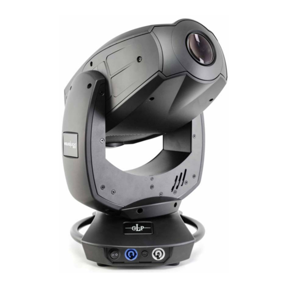
1 Description of Device 1. Moving head (actively cooled) 2. Arm with various cooling vents 3. LCD-Display/Menu (data entry) 4. Base with various connectors and Camlock mounting system 5. Carrying handle. Also used to attach the safety cable 6. DMX- Output (3 pin) 7. -
Page 5: Safety Instructions
8. Repair, maintenance, and installation work shall be done by qualified or GLP certified staff only. You need to pay attention to the common rules of technology that are not explicitly mentioned in this manual. 9. Use only original GLP spare parts. Any structural modification of the system will terminate all warranty claims. -
Page 6: Preparation And Installation
2 Preparation and Installation 2.1 Mounting T is fully operational whether it hangs or is mounted to a wall. It can also be operated while standing on the floor. Keep a safety distance of 0.5 m from any easily inflammable materials (decoration etc.). Pay attention to the regulations of: BGV C1 (former VBG 70), DIN VDE 0711-217 and BGI 810-3. -
Page 7: Mounting In Hanging Position (Head Down)
2.1.2 Mounting in hanging position (Head down) To operate the T in an hanging position, please attach one half-coupler centrically with a M10 thread bolt (max. length 11 mm). You can also use a dedicated mounting plate which is attached to the fixture through two Camlock quick connectors see section below. -
Page 8: Securing The Device
2.2 Securing the Device Regardless of the mounting method of the T you'll have to use a stipulated safety wire. Swipe it through one of the two handles of the fixture and connect it to the primary support structure. Pay attention to a safe and proper fastening. -
Page 9: Dmx
2.3.3 DMX USITT DMX-512 Standard input/output in 3 & 5 pin connectors. 3 pin: Pin 1 = [Ground] / Pin 2 = [-] / Pin 3 = [+] 5 pin: Pin 1 = [Ground] / Pin 2 = [-] / Pin 3 = [+] / Pin 4/5 n.c. The DMX- Addressing starts at the DMX- Address [001]. - Page 10 BACK - ENTER Level1 Level 2 Level 3 Level 4 Remark Special Manual control for special White Temp Manual control for White Temperature Dimmer Manual control for the Dimmer Shutter Manual control for the Shutter Blue Manual control for blue Green Manual control for green Manual control for red...
- Page 11 BACK - ENTER Level1 Level 2 Level 3 Level 4 Remark Set DMX Image Set Image if Activates a stored scene if DMX is off DMX off Save Image in Stores the scene currently sent to the Memory unit Indicates the presently received DMX DMX Monitor signal per DMX channel Instantaneous value for Pan...
-
Page 12: Dmx Channel Selection (Dmx Protocol)
BACK - ENTER Level1 Level 2 Level 3 Level 4 Remark RESET and new calibration for all Reset fixture functions 4 DMX Channel Selection (DMX Protocol) Normal-Mode 20 DMX channels Channel Function Time and Value 1) PAN- 0 .. 660° 0..255 00..FF 0..100... - Page 13 Channel Function Time and Value 12) Gobo 1 Open position 0..15 0..0F 0..5.5 (indexed) Gobo 1 16..31 10..1F 6..12 Gobo 2 32..47 20..2F 12.5..18 Gobo 3 48..63 30..3F 19..24.5 Gobo 4 64..79 40..4F 25..31 Gobo 5 80..95 50..5F 31.5..37 Gobo 6 96..111 60..6F 38..43.5...
- Page 14 Channel Function Time and Value 180° 20..21 14..15 270° 22..23 16..17 0° 24..25 18..19 90° 26..27 1A..1B 10,4 180° 28..29 1C..1D 11,2 270° 30..31 1E..1F TILT size / phase see also PAN 32..63 20..3F 13..25 PAN / TILT size / phase see also PAN 64..95 40..5F 26..37...
- Page 15 Channel Function Time and Value Shutter open then down-dimming slow - fast 80..111 50..6F 32..43 (random patterns) Up-dimming then down-dimming slow - fast 112..143 70..8F 44..56 (random patterns) Strobe effect pause 5s .. 1s 144..199 A0..C7 57..77 Strobe effect, slow - fast 1 Hz ..
- Page 16 Extended-Mode 20 DMX channels Channel Function Time and Value 1) PAN- 0 .. 660° 0..255 00..FF 0..100 coarse 2) PAN-fine High- Pos ... High- Pos + 2,6° (16 Bit) 0..255 00..FF 0..100 3) Tilt- 0 .. 300° 0..255 00..FF 0..100 coarse 4) Tilt-fine High- Pos …...
- Page 17 Channel Function Time and Value Gobo 7 57..63 39..3F 23..24.5 Gobo 8 64..71 40..47 25..27.5 Gobo 9 72..79 48..4F 28..31 Gobo 10 80..87 50..57 31.5..34 Gobo 11 88..95 58..5F 34.5..37 Gobo wheel rotation CCW slow fast 130..193 82..C1 51..75.5 Gobo wheel rotation CW fast slow 194..254 C2..FE...
-
Page 18: Changing Gobos
Shutter open then dimming out (random) 80..110 60 sec..30 sec 0.3 sec..0.1 sec Dimming in then dimming out (random) 112..142 60 sec..30 sec 0.3 sec..0.1 sec Additional Display Indications As a default you'll find the following additional information in the first row of the LCD display: x x / x x / x x / x x / x ( e . -
Page 19: Changing Rotating Gobos (Wheel 1)
pencil tip and its reflection Attention: Customized gobos like company logos, or those with writing also need to be placed in the holder with the correct orientation to ensure that the projected image reads correctly. Place the side of the gobo which reads correctly towards the LED light engine to ensure that it projects properly. -
Page 20: Safety Regulations
6.1 Safety regulations • Disconnect the fixture from the mains power before commencing any maintenance work! • Wait minimum 15 minutes after removing the power to allow the fixture to cool down. 6.2 Circumference and Interval (rule-of-thumb) The maintenance schedule of any given fixture depends on the installation environment. -
Page 21: Technical Specifications
7 Technical Specifications Power supply Power consumption 400 VA (Watt) Power Input/Output ~100-240 V AC, 50-60 Hz (auto sensing input) Power connectors NEUTRIK powerCON Power-in: NAC3FCA / NAC3MPA (blue) Power-out: NAC3FCB / NAC3MPB (grey) Fuse protection Micro-fuse 5x20 mm, T5A Operational Parameters Max. -
Page 22: System Dimensions (In Mm)
8 System dimensions (in mm) 215,5 291,31 German Light Products GmbH (Instruction version 1.01) / from software version 1.07... -
Page 23: Rotating Gobo Wheel
Rotating Gobo wheel Gobo 1 Gobo 2 Gobo 3 Gobo 4 Gobo 5 Gobo 6 Gobo 7 German Light Products GmbH (Instruction version 1.01) / from software version 1.07... -
Page 24: Fixed Gobo Wheel
Fixed Gobo wheel Gobo 1 Gobo 2 Gobo 3 Gobo 4 Gobo 5 Gobo 6 Gobo 7 Gobo 8 Gobo 9 Gobo 10 Gobo 11 German Light Products GmbH (Instruction version 1.01) / from software version 1.07... -
Page 25: Index
9 Index Mounting............6 Mounting in hanging Position......7 BGV C1 ............6 Mounting in sidewise Position......7 Mounting on the Floor ........6 Circumference..........20 Cleaning............19 NEUTRIK powerCON ........8 Compressed-Mode........14 Normal-Mode ..........12 Danger of BURNING........5 Optical parts .......... - Page 26 German Light Products GmbH (Instruction version 1.01) / from software version 1.07...
Need help?
Do you have a question about the VOLKS LICHT SPOT and is the answer not in the manual?
Questions and answers