
Related Manuals for GLP Volks Licht R-G-B


Summary of Contents for GLP Volks Licht R-G-B
- Page 1 R-G-B from software version 1.15 (Instruction version 1.7) e-mail: service@glp.de Internet: http://www.glp.de...
- Page 2 Notes: German Light Products GmbH (Instruction version 1.7) / from software version 1..15)
-
Page 3: Table Of Contents
Table of content Description of Device....................4 1.1 Safety Instructions .................... 5 Preparation and Installation ................... 6 2.1 Mounting ......................6 2.1.1 Mounting on the floor (upright) ............. 7 2.1.2 Mounting in hanging position (Head down) .......... 7 2.1.3 Mounting in a sideway Position............7 2.2 Securing the Device .................. -
Page 4: Description Of Device
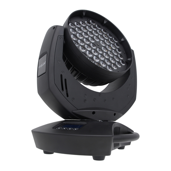
1 Description of Device 1. Moving head (actively and passively cooled) 2. Arm with various cooling vents 3. LCD-Display/Menu (data entry) 4. Base with various connectors and Camlock mounting system 5. Carrying handle. It is also used to attach the safety cable 6. -
Page 5: Safety Instructions
Safety Instructions T is an advanced technology product. To guarantee smooth operation, it is necessary to follow the following instructions. The manufacturer of this device will not take responsibility of damages through any disregard of the information in this user manual. -
Page 6: Preparation And Installation
11. Repair-, maintenance- and installation work should only be performed by qualified or GLP certified staff. You need to pay attention to the common rules of technology that are not explicit mentioned in this manual. 12. Use only original spare parts. Any structural modification on the system will terminate all warranty claims. -
Page 7: Mounting On The Floor (Upright)
Pay attention to the regulations of: BGV C1 (former VBG 70) and DIN VDE 0711-217. The installation shall be done by qualified staff only. For the various mounting positions of the T (standing on the floor, sideways or hanging) different accessories kits are available. Using any required kits, along with the standard mounting connectors on the base of the fixture, will ensure a safe and firm installation. -
Page 8: Securing The Device
two truss belts. Never use the "Mounting in hanging position" technique described above to secure the fixture in a sideway position, as the fixtures base can become damaged, and a secure installation cannot be assured. 2.2 Securing the Device Regardless of the mounting method of the T you'll have to use a secondary safety wire. -
Page 9: The Menu Field
The Menu Field You'll find the illuminated control board on the upper side of DMX Start Address the base. It allows you to make all necessary adjustments of the system. The current DMX address will be shown on the top level of the menu. - Page 10 Key code Use the code for entering the calibration menu (for Adjust xxxx authorized persons only) Diagnose Diagnose functions Pan Offset Calibration for Pan-Offset Tilt Offset Calibration for Tilt-Offset Clear Erase EEPROM memory EEPROM P/T Speed Normal Speed and Fast Speed Temperatures Indicates the head and base temperature Testmode...
-
Page 11: Dmx Channel Selection (Dmx Protocol)
4 DMX Channel Selection (DMX Protocol) Channel Function Time and Value 1) PAN- 0 .. 660° 0..255 00..FF 0..100 coarse 2) PAN-fine High- Pos ... High- Pos + 2,6° (16 Bit) 0..255 00. .FF 0..100 3) Tilt- 0 .. 300° 0..255 00..FF 0..100... - Page 12 Channel Function Time and Value 270° 06..07 06..07 0° 08..09 08..09 90° 10..11 0A..0B 180° 12..13 0C..0D 270° 14..15 0E..0F 0° 16..17 11..11 90° 18..19 12..13 180° 20..21 14..15 270° 22..23 16..17 0° 24..25 18..19 90° 26..27 1A..1B 10,4 180° 28..29 1C..1D 11,2...
-
Page 13: Maintaining And Cleaning The V O L K S L I C H T
5 Maintaining and Cleaning the T is a low maintenance fixture. It is only necessary to clean the air inlets and outlets as well as the optical LED lenses from time to time. For safe operation it is absolutely essential that the fixture is kept clean and that dust, dirt and smoke-fluid residues must not build up on, or within, the fixture. -
Page 14: Technical Specifications
6 Technical Specifications Power supply Power consumption 180 VA (Watt) Power Input ~100-240 V AC, 50-60 Hz (auto sensing input) Fuse protection Micro-fuse 5x20 mm, T2A Operational Parameters Max. Ambient 45° C / 113° F (integrated overheating switch) Temperature Mounting Position Any (see chapter mounting) Lighting System - Additive Color mixing LED Type... -
Page 15: System Dimensions (In Mm)
7 System dimensions (in mm) German Light Products GmbH (Instruction version 1.7) / from software version 1..15) -
Page 16: Index
8 Index Mounting in sidewise Position ......7 Mounting on the Floor ........7 BGV C1............6 Optical parts ..........13 Circumference ..........13 Cleaning............13 Pan- Movement ..........14 Power Supply ..........8 Description of Device ........4 DIN VDE 0711-217 .......... 6 DMX .............. - Page 17 German Light Products GmbH (Instruction version 1.7) / from software version 1..15)
Need help?
Do you have a question about the Volks Licht R-G-B and is the answer not in the manual?
Questions and answers