Table of Contents
Advertisement
Quick Links
60-91 class
■組立前に必ずこの説明書を最後まで、よくお読みになり、
正しくお使い下さい。
■この説明書は「EC135」専用の部分についてのものです。
「60スケールシリーズ」共通の部分は、メカニカルキッ
ト説明書をお読み下さい。特に「安全のために必ずお守
り下さい」は、飛行前に必ず読んで下さい。
■この説明書は、大切にお手元に保管して下さい。
※製品改良のため、予告なく仕様を変更する場合があります。
eurocopter
■Please read this manual in its entirety before attempting
■This manual explains the parts exclusive to EC135. For
■Keep this manual in a safe place.
※Changes in product specifications may be effected
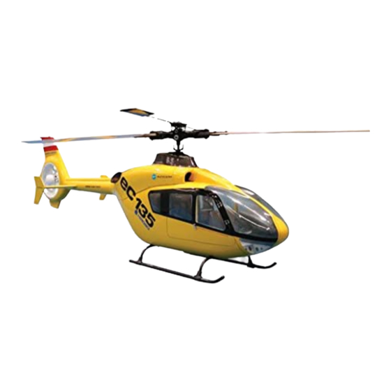
SCALE HELICOPTER
EC135
BODY KIT
INSTRUCTION MANUAL
to assemble the helicopter.
parts common to the 60 scale series, please read the
mechanical kit manual. In particular, please read the
section entitled 'Always follow these rules for safety'
before attempting to fly the helicopter.
without notice.
MADE IN JAPAN
取扱説明書
2002
No. 10893
Advertisement
Table of Contents

Subscribe to Our Youtube Channel
Related Manuals for Hirobo EC135


Summary of Contents for Hirobo EC135
- Page 1 ■Please read this manual in its entirety before attempting ■組立前に必ずこの説明書を最後まで、よくお読みになり、 to assemble the helicopter. 正しくお使い下さい。 ■This manual explains the parts exclusive to EC135. For ■この説明書は「EC135」専用の部分についてのものです。 parts common to the 60 scale series, please read the 「60スケールシリーズ」共通の部分は、メカニカルキッ mechanical kit manual. In particular, please read the ト説明書をお読み下さい。特に「安全のために必ずお守...
-
Page 2: Table Of Contents
目 次 Contents コクピットの組立 ............... P.2 Cockpit assembly ..............P.2 計器盤の組立 ............... P.3 Dashboard assembly ............P.3 座席の組立 ................P.4 Sheet assembly ..............P.4 アクセサリーの取付 -1 ............P.4 Attaching the accessories-1 ..........P.4 トップカバーの取付 ............P.5 Attaching the top cover ............P.5 スキッドの組立 ..............P.6 Skid assembly ..............P.6 テールパイプの取付 ............P.7 Attaching the tail pipe ............ -
Page 3: コクピットの組立
コクピットの組立 Cockpit assembly ① 胴枠にフロア部分を固定するためのベニヤ板をエポ ① Use epoxy adhesive to attach the plywood which will キシ接着剤で貼り付けます。 fix the floor section to the fuselage frame. 横から見た図 Side view ② フロア部分になる胴枠を組み立てます。 太線の部分は、ボディと合わせながらぴったり 合う様にヤスリ等で修正します。 ② Assemble the fuselage frame which will be the floor section. Align the part marked with the thick line to the body and trim with a file so that it fits perfectly. カットします Cut off 横から見た図 Side view ③ Trim the outside so that the fuselage frame which will ③ 隔壁となる胴枠はこの位置でぴったり合う様に be the partition wall fits perfectly at this position. 外型を修正します。 After trimming, use epoxy adhesive to attach the 修正後、受信機台となる胴枠をエポキシ接着剤 fuselage frame which will be the receiver mount. で接着します。 受信機台... -
Page 4: 計器盤の組立
計器盤の組立 Dashboard assembly ① Assemble the plywood with epoxy adhesive. ① ベニヤ板をエポキシ接着剤で組み立てます。 Trim each piece of plywood with a file so that they 各ベニヤ板はピッタリ合う様にヤスリ等で修正します。 fit perfectly. カットします Cut off ② ラインに沿って切り取り、 瞬間接着剤で接着します。 ② Cut along the line and attach with instant adhesive. Fill any gaps with putty. 隙間はパテなどで埋め、修正します。 のりしろを約 2mm 残して 外周をカットします。 Cut around the edges leaving a 2mm margin for the adhesive. ③ ①と②を組み合わせた時に隙間が 出来ない様に図の箇所をヤスリ等 で削ります。 Use a file to as shown in the figure to ensure that there is no gap when assembling ① and ② . 角を削る コクピットに合わせてみて、 Cut away the corner. よければエポキシ接着剤で接 着します。... -
Page 5: 座席の組立
座席の組立 Sheet assembly 座席はラインに沿って切り取り、瞬間接着剤で 接着します。 隙間がある場合はパテなどで修正します。 2 個作ります。 Cut away the seat along the line and attach it with instant adhesive. Fill any gaps with putty. Make two of them. はめ込みます Fit together. はめ込みます Fit together. アクセサリーの取付 -1 Attaching the accessories-1 M2×5TS ………………… 2 M3×8TS ………………… 4 操縦桿 Control lever M2.6×6 ト ラスTS ………… 4 M2.6×6 truss TS ワイパー M3 × 8TS Wiper M2.6 × 6 トラス TS M2.6 ×... -
Page 6: Attaching The Top Cover
トップカバーの取付 Attaching the top cover スターターシャフト用にφ10の穴をあけ ます。 (オプションの S60-IIセルフスター ターキットを使用する場合は、穴をあけ る必要はありません。 ) Open a φ10 hole for the starter shaft. (It is not necessary to open the hole when 補強ベニヤ …………… 14 using the optional S60-II self-starter kit.) Reinforcement plywood 53.5 10 × 10 ベニヤ板をボディ内側よりエポキシ 接着剤(30 分以上硬化型)もしくは FRP 樹脂 で貼り付けます。貼り付ける際は接着面をサ ンドペーパーでサンディングし、アルコール で油分をふき取ります。 Attach a 10 × 10mm piece of reinforcement plywood to the inside with epoxy (30 minute hardening type). Sand the contact surfaces with sanding paper and wipe any oil away with alcohol before attaching. -
Page 7: Skid Assembly
スキッドの組立 Skid assembly スケール感を出すため後ろのパイプ を 10mm カットします。 M3×5SS ………………… 8 Cut the rear pipe 10mm from the rear pipe to achieve a feeling of scale. 組立後瞬間接着剤 を使用します。 Use cyanoacrylate glue after assembling. M3 × 5SS 瞬間接着剤 Cyanoacrylate glue 90° 90° ※□コクピットの組立 ⑤で、コピーして使用して下さい。 ※ Make a copy of this illustration and use it in step ⑤ on page 2. -
Page 8: Attaching The Tail Pipe
テールパイプの取付 Attaching the tail pipe ① テールドライブ ASSY L=507 のグラスパイプを下図 ① Cut 100mm of the glass pipe of the tail drive assembly のようにボールジョイント側から 100mm カットし L=507 from the ball joint side as shown below. M3×18CS ……………… 4 ます。 ② Temporarily assemble the frame assembly, the tail ② フレーム ASSY、テールドライブ ASSY P=198、テー drive assembly P=198, tail drive assembly L=507 and ルドライブASSY L=507、 フェネストロンの仮組をし the fenestron into the fuselage. ます。 ③ Determine the position of the tail drive assembly ③ テールドライブ ASSY L=507 とフェネストロンが一 L=507 where it comes into line with the fenestron. 直線につながる様に、 テールドライブASSY L=507の ④ After the position is determined, drill 2.1mm holes to 位置を決めます。 the both sides in accordance with those of the ④... -
Page 9: Attaching The Accessories-2
アクセサリーの取付 -2 Attaching the accessories-2 Use epoxy adhesive (30 minute hardening type) to 図の位置に排気管をエポキシ接着剤 (30分以上硬化 ○ ○ attach the exhaust pipe at the place shown in the 型)で取り付けます。L、R に注意して下さい。 figure. Ensure that the left and right sides are テール部にアンテナ(ピアノ線)を取り付けます。 ○ attached in the correct places. Attach the antenna (piano wire) to the tail section. ○ 約 20mm Approx. 20mm エポキシ Epoxy エポキシ Epoxy φ 2 穴をあけます Open φ 2 holes. エポキシ Epoxy... -
Page 10: Attaching The Windows
ウインドウの取付 Attaching the windows ① ボディの各ウインドウは外側のラインに合わせ、 ウ ① Cut away the fuselage windows along the outside line インドウ貼付しろを約 3mm 残して切り取ります。 leaving approximately 3mm of margin to attach the ② 各ウインドーはケガキ線より多めにカットし、ボ windows. ディに合わせて形を整えます。 ② Cut away the windows just outside the marking line ③ 各ウインドーをボディーの表からキャノピーボンド and align them with the body. 又はエポキシ接着剤で接着します。 ③ Attach the windows from the outside of the body using canopy bond or epoxy adhesive. 注 意 Caution FRPを接着する時は必ず接着面をサンドペーパー等 で粗してから接着して下さい。 Before bonding the FRP, make sure to rasp the bonding surface by using a sandpaper, etc. エポキシ Epoxy 尾翼をエポキシ接着剤で接着します。 Bond the tail stabilizers with epoxy adhesive. カットします Cut off カットします Cut off カットします Cut off 10mm L1, L2, R1, R2に合わせて図のようにカット... -
Page 11: Attaching The Doors
ドアの取付 15mm Attaching the doors 図のように曲げます。 Bend as shown in the 10mm drawing. M1.7×5TS ………………4 φ 1.2 ピアノ線を 30mm に カットして使います。 Cut the φ1.2 piano wire to M1.7×5PH………………16 approx. 30mm for use. M1.7 ナット φ 1.8 穴開け O リング P-3 M1.7 nut Drill 1.8mm O-ring P-3 M1.7ナ ッ ト ………………16 holes φ 3 × 8 × 0.5FW M1.7 nut φ... -
Page 12: Attaching The Fenestron
フェネストロンの取付 Attaching the fenestron M2 ロッドエンド M2 × 6CS M2 rod end アジャストジョイント B Adjust joint B EX φ 5 ボール EX φ 5 ball φ 1.7FW M2.6 × 16 座付 TS M2.6 × 16 TS with washer 約 13mm Approx. ラダーサーボ 13mm Rudder servo M2 ナット M2 nut ハンダ付け Solder SUS パイプとφ 5 ボールが一直線に なる位置にエポキシで接着します。... - Page 13 M2 × 45 クロスメンバー M2 × 45 cross member φ 1.7FW ………………14 M2×6PH ………………14 M2×45ク ロス メ ンバー ……7 M2×45 cross member φ 1.7FW M2 × 6PH ラダーのセッティング Rudder setting Set the throttle control stick of the transmitter to neutral. 送信機のエンコンスティックを中心にします。 Attach the linkage rod to the fenestron pitch lever and そしてラダースティックとトリムがニュートラル position the servo horn at 90° when rudder stick and trim になっている時にフェネストロンピッチレバーと are in their respective neutral positions. サーボホーンが 90° になる位置に取り付けます。 90° 90° The rudder neutral position, ラ...
-
Page 14: Attaching The Receiver And The Battery
受信機・バッテリーの取付 Attaching the receiver and the battery コクピット内またはコクピットフロア下 に受信機用のバッテリーや受信機、セル フスターター用バッテリーなどをスポン ジ等でくるみ、重心を調整して下さい。 Wrap the receiver battery, receiver and self- starter battery in sponge etc, place them in the cockpit or under the cockpit floor, and adjust the center of gravity. 受信機台に取り付ける ことも出来ます。 Can also be attached to the receiver mount. -
Page 15: Attaching The Main Frame And The Skid
メインフレーム・スキッドの取付 Attaching the main frame and the skid ① 使用するマフラーに合わせて排気口をカットして下 ① Trim the fuselage to fit the muffler. さい。 ② Install the main frame into the fuselage. Before ② 胴体にメインフレームを組込みます。フレームを固 mounting the frame, insert the tail drive assembly φ 3×9×1FW ………………4 定する前にテールドライブ ASSY P=198 をテールド P=198 into tail drive assembly L=507. ライブ ASSY L=507 に差し込んでおきます。 テールドライブ ASSY L=507 Tail drive assembly L=507 テールドライブ ASSY P=198 Tail drive assembly P=198 φ 3 × 9 × 1FW M3 ×... -
Page 16: Attaching The Rotor Head And The Top Cover
M6 ロッドエンド M2.6 × 15CS M6 rod end クロスメンバー M3 × 26 M2.6 穴付 M2.6×15CS …………… 4 Cross member M3 × 26 with M2.6 holes M3 × 15 全ネジ M3 × 15 thread screw M3×15全ネジ …………… 4 φ 6 ボール M3 ナット M3×15 thread screw φ 6 ball M3 nut クロスメンバー L=26 を外し、クロスメン カラーφ... -
Page 17: Affixing The Decals
デカールの貼付 Affixing the decals 機体番号、国番号などは実機の写真を参考にして貼る It may be easier to affix the fuselage number and country とよいでしょう。 number by referring to the photo. -
Page 18: Data Sheet
Data sheet Transmitter:FUTABA FF9-H 1ch(AIL) 2ch(ELE) 3ch(THR) 4ch(RUD) 5ch(GYR) 6ch(PIT) (R/U) 100% 100% 100% 100% 100% 100% (L/D) 100% 100% 100% 100% 100% 100% 100% ----- 100% ----- ----- ----- 100% ----- ----- ----- ----- ----- ----- ----- ----- NORM NORM NORM NORM... - Page 19 補修パーツについて ※ Spare parts are available for direct sales from HIROBO, but only in Japan. ●補修パーツのご購入につきましては、キットを購入された模型店へコード番号と名称を言ってお買い求め下さい。 ●上記の方法で購入が困難な場合は、直接当社へ下記要領にてお申し込み下さい。 ●お届け 商品は小包にて、ご注文受付日から3日〜7日後にお届けいたします。 週末、年末年始、GW、お盆休み中のご注文は、休み明けから3日〜7日後とさせていただきます。 月初めは棚卸しのため1日〜3日ほど余分にお時間をいただくこともあります。あらかじめご了承下さい。 ●商品の交換 商品の不良、配送上の破損、ご注文と違う商品が届いた場合は、お手数ですが商品到着8日以内にお電話 (0847-40-0088)パーツ係までご連絡の上、ご返送下さい。返送料は当社で負担いたします。 お客様のご都合による返品 ・ 交換は受け付けており ませんので、 コー ドNo、 品名、 数量を ご確認の上、 ご注文く ださい。 ※コードNo、品名は商品に表示してあります。商品が届いてすぐに内容をご確認ください。 ●お申し込み方法(現金書留または代金引換にてお受けしております) 代金引換 現金書留 注文書同封の上、お申し込みください。...
- Page 20 0414-064 2534-023 0414-052 2511-030 2539-015 2532-031 2531-001 2525-006 2534-023 0414-059 2500-094 0414-049 2505-009 0414-063 2534-016 0414-051 2506-017 2500-095 2533-019 0414-061 2533-003 0414-055 2534-005 2500-098 2521-087 0414-058 0414-057 0414-060 0414-050 2500-098 0414-062 0414-054 0414-056 2500-068 2533-019 2509-016 2505-009 0414-053 0414-005 2500-097 2500-057 2532-050 0414-047...
- Page 21 コ ー ド 品 名 入 数 価 格 (円) 備 考 i t r y t ' ユ ニ バ ー サ ル ハ ブ ロ ー ル ピ ン 付 テ ー ル ド ラ イ ブ シ ャ...
- Page 22 0414-269 0414-275 0414-273 0414-270 0404-276 0414-272 2523-019 0400-090 2524-001 0414-274 0414-069 2534-023 2505-012 0404-468 0414-271 0414-070 2533-019 0414-278 2532-049 0405-251 2525-010 2539-008 2521-078 2505-002 2511-005 2532-049 0414-280 2525-010 2521-078 2506-009 2505-013 0414-281 0404-277 0414-279 60 class 60 class SCALE HELICOPTER MECHANICAL KIT SCALE HELICOPTER EC-135...
- Page 23 コ ー ド 品 名 入 数 価 (円) 格 備 考 i t r y t ' ア ジ ャ ス ト ジ ョ イ ン ト 新 防 振 ゴ ム セ ッ ト 防 振 ゴ ム と...
- Page 24 726-0004 〒 HIROSHIMA-PREF., JAPAN. 〒726-0004 TEL: ( 0847 ) 40-0088 (代) FAX:45-7670 TEL:0847-40-0088 FAX:0847-45-7670 http://model.hirobo.co.jp/ http//model.hirobo.co.jp/ 注意 Caution ①本書の内容の一部または全部を無断で転載することは禁止されています。 ②本書の内容については、将来予告なしに変更することがあります。 ③本書の内容について万全を期しておりますが、万一ご不審な点や誤り、記載もれなどお気付 きのことがありましたら、ご一報くださいますようお願いいたします。 ④運用した結果については③項にかかわらず責任を負いかねますので、ご了承ください。 ①Reproduction of this manual, or any part thereof is strictly prohibited. ②The contents of this manual are subject to change without prior notice.
Need help?
Do you have a question about the EC135 and is the answer not in the manual?
Questions and answers