Table of Contents

Related Manuals for KROHNE OPTISONIC 6400


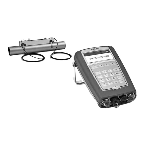
Summary of Contents for KROHNE OPTISONIC 6400
- Page 1 OPTISONIC 6400 OPTISONIC 6400 OPTISONIC 6400 OPTISONIC 6400 Handbook Handbook Handbook Handbook Portable ultrasonic clamp-on flowmeter Electronic Revision: ER 1.1.0_ (SW.REV 01.01.01) © KROHNE 08/2011 - 4000972602 - MA OPTISONIC 6400 R02 en...
- Page 2 All rights reserved. It is prohibited to reproduce this documentation, or any part thereof, without the prior written authorisation of KROHNE Messtechnik GmbH. Subject to change without notice. Copyright 2011 by KROHNE Messtechnik GmbH - Ludwig-Krohne-Str. 5 - 47058 Duisburg (Germany) www.krohne.com 08/2011 - 4000972602 - MA OPTISONIC 6400 R02 en...
-
Page 3: Table Of Contents
3.4.6 Step 6: set up counters for energy ..................37 3.4.7 Step 7: How to read energy measurement................37 4 Electrical connections 4.1 Safety instructions......................39 4.2 Location of connectors at the converter ................ 39 08/2011 - 4000972602 - MA OPTISONIC 6400 R02 en www.krohne.com... - Page 4 7.2 Technical data......................... 71 7.3 Dimensions and weights ....................77 7.3.1 Clamp-on sensor ........................77 7.3.2 Converter..........................78 7.3.3 I/O box ........................... 79 7.3.4 Trunk on wheels........................80 8 Notes www.krohne.com 08/2011 - 4000972602 - MA OPTISONIC 6400 R02 en...
-
Page 5: Safety Instructions
If an inline measurement device is broken and you are in need of the information the OPTISONIC 6400 might be the solution for you. -
Page 6: Safety Instructions From The Manufacturer
The manufacturer reserves the right to alter the content of its documents, including this disclaimer in any way, at any time, for any reason, without prior notification, and will not be liable in any way for possible consequences of such changes. www.krohne.com 08/2011 - 4000972602 - MA OPTISONIC 6400 R02 en... -
Page 7: Product Liability And Warranty
This document is provided to help you establish operating conditions, which will permit safe and efficient use of this device. Special considerations and precautions are also described in the document, which appear in the form of underneath icons. 08/2011 - 4000972602 - MA OPTISONIC 6400 R02 en www.krohne.com... -
Page 8: Warnings And Symbols Used
This symbol designates all instructions for actions to be carried out by the operator in the specified sequence. RESULT RESULT RESULT RESULT This symbol refers to all important consequences of the previous actions. www.krohne.com 08/2011 - 4000972602 - MA OPTISONIC 6400 R02 en... -
Page 9: Device Description
7 Power adapter including plugs for EU, UK, US and AUS 8 USB memory stick, measure band optionally I/O box and/or temperature sensors, PC connection cable 9 Signal converter UFC 400 P 08/2011 - 4000972602 - MA OPTISONIC 6400 R02 en www.krohne.com... -
Page 10: Nameplates
1 Name and address of the manufacturer 2 Device type 3 Manufacturing year 4 Serial number 5 Protection class and temperature data 6 Treat device as electronic garbage according WEEE rules. www.krohne.com 08/2011 - 4000972602 - MA OPTISONIC 6400 R02 en... - Page 11 DEVICE DESCRIPTION OPTISONIC 6400 Figure 2-4: I/O box, standard version Figure 2-5: I/O box with 2 OPTITEMP TT 30 C included. 08/2011 - 4000972602 - MA OPTISONIC 6400 R02 en www.krohne.com...
-
Page 12: Installation
Specific for converters: WARNING! Be careful moving the handle of the converter, as your fingers may get stuck between the handle and the housing of the converter. This may cause injury. www.krohne.com 08/2011 - 4000972602 - MA OPTISONIC 6400 R02 en... -
Page 13: Installation Requirements
Please follow the installation recommendations in the next installation position examples. Figure 3-1: Inlet, outlet and recommended mounting area 1 Min. 10 DN 2 Min. 5 DN 3 OK, 120° 08/2011 - 4000972602 - MA OPTISONIC 6400 R02 en www.krohne.com... -
Page 14: Long Horizontal Pipes
Ensure that the pipe is fully filled at all times. • Both ascending and descending flow direction is measurable. • Observe the required in- and outlets. • Figure 3-3: Mounting on vertical pipelines is possible www.krohne.com 08/2011 - 4000972602 - MA OPTISONIC 6400 R02 en... -
Page 15: Open Feed Or Discharge
Figure 3-5: Down going pipeline over 5 m / 16 ft length 3.2.6 Position of control valve Always install control valves downstream of flowmeter in order to avoid cavitation or distortion of flow profile. Figure 3-6: Position of control valve 08/2011 - 4000972602 - MA OPTISONIC 6400 R02 en www.krohne.com... -
Page 16: Position Of Pump
OPTISONIC 6400 3.2.7 Position of pump CAUTION! Never install flowmeter at a pump suction side in order to avoid cavitation or flashing in the flowmeter. Figure 3-7: Position of pump www.krohne.com 08/2011 - 4000972602 - MA OPTISONIC 6400 R02 en... -
Page 17: Installation Procedure For Flow Measurement
7 Power adapter including plugs for EU, UK, US and AUS 8 USB memory stick, measure band optionally I/O box and/or temperature sensors, PC connection cable 9 Signal converter UFC 400 P 08/2011 - 4000972602 - MA OPTISONIC 6400 R02 en www.krohne.com... -
Page 18: Step 2: Select Proper Installation Position
This menu will be shown only once. You can activate the menu to be shown again at the next startup by selecting "Settings and information Device Start-up sequence?". www.krohne.com 08/2011 - 4000972602 - MA OPTISONIC 6400 R02 en... -
Page 19: Step 5: Program The Units In The Converter
If you use the converter for the first time, it will prompt you for the unit setting automatically. Otherwise go to menu number 2.4.1 ("Measurement Setup Units") Choose in each line the required unit with the buttons as shown in the previous section. 08/2011 - 4000972602 - MA OPTISONIC 6400 R02 en www.krohne.com... -
Page 20: Step 6: Program The Converter
The correct value will be measured. VoS Fluid Velocity of Sound. Only change it if it is well known. Viscosity Only change it if it is well known. Choose next www.krohne.com 08/2011 - 4000972602 - MA OPTISONIC 6400 R02 en... -
Page 21: Step 7: Mount The Sensor Rails
Small 2 MHz, 1 rail DN50...250 Medium 1 MHz, 1 rail DN200...750 Medium 1 MHz, 2 rails DN400...1500 Medium 1 MHz, 2 rails Choose the right traverse mode. For recommendations please see examples above. 08/2011 - 4000972602 - MA OPTISONIC 6400 R02 en www.krohne.com... - Page 22 For V mode with 2 rails you must install the DOWN rail in line with UP rail. It is easier to install than the Z mode, but you need more free pipe length. www.krohne.com 08/2011 - 4000972602 - MA OPTISONIC 6400 R02 en...
- Page 23 1 Advised distance 1 = 2 + 3 W mode; 1 rail (DN15...150) Follow the instructions as given in "V mode; 1 rail V mode; 1 rail V mode; 1 rail V mode; 1 rail". 08/2011 - 4000972602 - MA OPTISONIC 6400 R02 en www.krohne.com...
- Page 24 Using this you can measure up to DN4000. Put the metal straps around the pipe. Put the sensor rail(s) on the pipe including the transducers with fixed cables. • 8: Repeat steps 1...7 for the second strap. www.krohne.com 08/2011 - 4000972602 - MA OPTISONIC 6400 R02 en...
- Page 25 INSTALLATION OPTISONIC 6400 Installation with textile straps (> DN250) Installation with textile straps (> DN250) Installation with textile straps (> DN250) Installation with textile straps (> DN250) 08/2011 - 4000972602 - MA OPTISONIC 6400 R02 en www.krohne.com...
- Page 26 Set the sensors to the proper sensor distance. Unlock and tilt the rail by pushing the buttons of the fixing units. Then put some coupling fat on the transducers and put the rail back by clicking. www.krohne.com 08/2011 - 4000972602 - MA OPTISONIC 6400 R02 en...
-
Page 27: Step 8: Connect The Sensor Cable
Signal < 10%: Signal < 10%: bad or no signal, check settings in menu, change transducer distance until there is Signal < 10%: Signal < 10%: at least a low signal 08/2011 - 4000972602 - MA OPTISONIC 6400 R02 en www.krohne.com... -
Page 28: Step 9: Start Flow Measurement
3.3.9 Step 9: start flow measurement Press " " on the UFC 400 P. The converter checks the received signal and initiates the flow measurement mode. The display will now show the actual flow. www.krohne.com 08/2011 - 4000972602 - MA OPTISONIC 6400 R02 en... -
Page 29: Error Messages
C5.3.7 active settings error during CRC check (Cyclic load settings; factory setting, back Redundancy Check) of the active up 1 or back up 2 settings 08/2011 - 4000972602 - MA OPTISONIC 6400 R02 en www.krohne.com... - Page 30 DSP and error microprocessor software www.krohne.com 08/2011 - 4000972602 - MA OPTISONIC 6400 R02 en...
-
Page 31: Installation Procedure For Energy Measurement
The converter can be placed in different ways. You can use the bracket to hang it or to place it on a desk or you can use the supplied strap to fix it to a pipe. INFORMATION! Observe the length of the signal cables. 08/2011 - 4000972602 - MA OPTISONIC 6400 R02 en www.krohne.com... -
Page 32: Step 1: Selecting The Necessary Tools For Energy Measurement
PT 100 sensors can be ordered optionally with the OPTISONIC 6400. In case temperature measurement is not possible there is an option in the UFC 400 P to set the temperature, read from another measurement, manually. - Page 33 1 PT 100 temperature transmitter 2 Hose clamp If the temperature sensors on the pipe have temperature transmitters 4...20 mA it is possible to make use of the standard I/O box. 08/2011 - 4000972602 - MA OPTISONIC 6400 R02 en www.krohne.com...
-
Page 34: Step 2: What To Do Before Setting Up The Energy Units
4...20 mA. 3.4.2 Step 2: what to do before setting up the energy units Installation procedure for flow measurement Follow the steps as descriped before, refer to page 17. www.krohne.com 08/2011 - 4000972602 - MA OPTISONIC 6400 R02 en... -
Page 35: Step 3: Setting Up The Units
13-04-2010 14:11:09 13 MB free If the recommended KROHNE energy set is used, only check the installed values of the "Current inputs". If another energy set is used, teach in the required values. The KROHNE temperature range is 4 mA = 0°C / 32°F and 20 mA = 120°C / 248°F. Extended range min and max is for an alarm function. - Page 36 Temperature input Temperature input Terminal A at supply Terminal A at supply Terminal A at supply Terminal A at supply Sensor location Supply Fluid Water 13-04-2010 14:11:09 13 MB free www.krohne.com 08/2011 - 4000972602 - MA OPTISONIC 6400 R02 en...
-
Page 37: Step 6: Set Up Counters For Energy
24 hour period. This is equal to 12000 BTU per hour or 3527 W. kilo calorie per second Power required to heat 1 kg of 4187 water with 1 degree Celsius in 1 second. 08/2011 - 4000972602 - MA OPTISONIC 6400 R02 en www.krohne.com... - Page 38 (2000 pounds or 907 kg) of ice. kilo calorie per second Amount of heat required to 4187 increase 1 kg of water with 1 degree Celsius. Therm Equal to 100000 BTU 105506000 www.krohne.com 08/2011 - 4000972602 - MA OPTISONIC 6400 R02 en...
-
Page 39: Electrical Connections
Check for the correct supply voltage printed on the nameplate. 4.2 Location of connectors at the converter All connectors are located at the bottom side of the converter. DISPLAY DC in LOGGER PQRS WXYZ MENU 08/2011 - 4000972602 - MA OPTISONIC 6400 R02 en www.krohne.com... -
Page 40: Power Supply
2 Connector for "DOWN" transducer (green) INFORMATION! You can measure two paths with this converter simultaneously. Use the left pair of connectors for path 1 and the right pair for path 2. www.krohne.com 08/2011 - 4000972602 - MA OPTISONIC 6400 R02 en... -
Page 41: Usb Connector
Figure 4-3: Using a memory stick for a measurement 1 Perform a measurement on site and log the data to the memorystick 2 Put the memory stick in your pc and evaluate the measurement. 08/2011 - 4000972602 - MA OPTISONIC 6400 R02 en www.krohne.com... -
Page 42: I/O Cable
• Plug the connector 2 of the I/O box 3 in the connector 1 of the converter. Then use the connectors 4 to setup the wanted I/O, as shown in the connection diagrams on the next pages. www.krohne.com 08/2011 - 4000972602 - MA OPTISONIC 6400 R02 en... - Page 43 Current input A- Current input B+ Current input B- Not connected Temperature sensor 2 (PT 100, 4 wire connection) Not connected Not connected Not connected Table 4-1: Terminals of I/O box 08/2011 - 4000972602 - MA OPTISONIC 6400 R02 en www.krohne.com...
-
Page 44: Connection Diagrams
Electronic or electromagnetic counter At frequencies above 100 Hz, shielded cables must be used to connect the counters. Internal resistance of the counter Button, NO contact or similar Table 4-2: Description of symbols www.krohne.com 08/2011 - 4000972602 - MA OPTISONIC 6400 R02 en... - Page 45 ≤ 32 VDC • U • I ≤ 22 mA ≥ 1.8 V • U ≤ (U • R ) / I • Not galvanically isolated. Figure 4-7: Current output passive I 08/2011 - 4000972602 - MA OPTISONIC 6400 R02 en www.krohne.com...
- Page 46 = 13.5 V at I ≤ 1 mA 0, nom = 12.5 V at I ≤ 10 mA 0, nom = 9.0 V at I ≤ 20 mA 0, nom www.krohne.com 08/2011 - 4000972602 - MA OPTISONIC 6400 R02 en...
- Page 47 0, max = 2 V at I ≤ 100 mA 0, max • The output is open when the device is de-energized. Figure 4-9: Status output / limit switch passive S 08/2011 - 4000972602 - MA OPTISONIC 6400 R02 en www.krohne.com...
- Page 48 ® HART connection active (point-to-point) ® Figure 4-11: HART connection active (I ® 1 HART communicator ® communicator must be R ≥ 370 Ω. The parallel resistance to the HART www.krohne.com 08/2011 - 4000972602 - MA OPTISONIC 6400 R02 en...
-
Page 49: I/O Configuration
• Switch on the I/O first • Go to the measurement mode to activate the I/O option that was switched on. • Simulate the required value in the "Simulation" menu. 08/2011 - 4000972602 - MA OPTISONIC 6400 R02 en www.krohne.com... -
Page 50: Operation
2 graphs showing both temperatures are shown. Additional screens showing trend graphs in measuring mode can be setup at the datalogger set up, go to "Measurement Setup Logger Logger setup View log in screens". www.krohne.com 08/2011 - 4000972602 - MA OPTISONIC 6400 R02 en... -
Page 51: Basic Settings Of Display
Only if free unit is chosen J factor Only if free unit is chosen Power Text Only if free unit is chosen W factor Only if free unit is chosen Specific heat Continue 08/2011 - 4000972602 - MA OPTISONIC 6400 R02 en www.krohne.com... - Page 52 (Sensor 1 position) Advised Sensor position Signal quality (Sensor 1 warning) No check No signal Shift sensor position Gain Signal quality Change settings Continue Abort installation (Sensor 1 position) Advised sensor position www.krohne.com 08/2011 - 4000972602 - MA OPTISONIC 6400 R02 en...
- Page 53 (Sensor 2 warning) No check VoS out of range Shift sensor position Gain Signal quality Change settings Continue Abort installation (Sensor 2 test) Volume flow Velocity of sound Signal quality 08/2011 - 4000972602 - MA OPTISONIC 6400 R02 en www.krohne.com...
- Page 54 Only if free unit is chosen Power Selection from list Text Only if free unit is chosen W factor Only if free unit is chosen Specific heat Selection from list Process input www.krohne.com 08/2011 - 4000972602 - MA OPTISONIC 6400 R02 en...
- Page 55 Selection from list Low flow cutoff threshold Low flow cutoff hysteresis Time constant Line 1 Parameter Selection from list Presentation format Selection from list Range 0% Range 100% Line 2 08/2011 - 4000972602 - MA OPTISONIC 6400 R02 en www.krohne.com...
- Page 56 Selection from list Sample interval Event logging Function Selection from list Status Selection from list Limit Measurement Selection from list Threshold Hysteresis Polarity Selection from list Direction Selection from list www.krohne.com 08/2011 - 4000972602 - MA OPTISONIC 6400 R02 en...
- Page 57 Low flow cutoff hysteresis Time constant 4mA trimming 20mA trimming Current inputs Function Selection from list Extended range A 0% Extended range A 100% Extended range B 0% Extended range B 100% 08/2011 - 4000972602 - MA OPTISONIC 6400 R02 en www.krohne.com...
- Page 58 Polarity Selection from list Limitation minimum Limitation maximum Low flow cutoff threshold Low flow cutoff hysteresis Time constant Invert signal Selection from list Pulse output Pulse shape Selection from list www.krohne.com 08/2011 - 4000972602 - MA OPTISONIC 6400 R02 en...
- Page 59 1 Items shown are dependent on settings in other menu items, e.g. 1 pipe / 2 pipes, 1 path / 2 paths, energy on / off, flow calculation on / off etc. Menu 3: View logged data Menu nr Menu item Remarks View logged data Select log file Select parameter configured list (Range setting) Offset Limit 08/2011 - 4000972602 - MA OPTISONIC 6400 R02 en www.krohne.com...
- Page 60 Not required for day to day use but may be asked for when support from the supplier is required. General Identification number Device serial number www.krohne.com 08/2011 - 4000972602 - MA OPTISONIC 6400 R02 en...
- Page 61 Dead time Detection path 2 Same as "Detection path 1" Service calibration zero device path 1 path 2 zero converter path 1 path 2 Reset to defaults Selection from list 08/2011 - 4000972602 - MA OPTISONIC 6400 R02 en www.krohne.com...
-
Page 62: How To Set Up Data Logging
Maximum number in one file is 150000 data points. If this number is exceeded during logging, the oldest datapoints are overwritten. The memory size for data logging is sufficient for 50 x 150000 data points. www.krohne.com 08/2011 - 4000972602 - MA OPTISONIC 6400 R02 en... - Page 63 If the polarity stands on "Normal" the polarity of the parameter is regarded. If the polarity stands on "Absolute value" the direction of flow is not regarded and events will be logged at for example both negative and positive values. 08/2011 - 4000972602 - MA OPTISONIC 6400 R02 en www.krohne.com...
-
Page 64: Step 2: How To Start Data Logging
2.4.4 Start/stop logger now Set start time Set start time Set start time Set start time Set stop time Arm/disarm logger Logger setup 13-04-2010 14:11:09 13 MB free www.krohne.com 08/2011 - 4000972602 - MA OPTISONIC 6400 R02 en... -
Page 65: Step 3: How To View Logged Data
The site files are XML files. You can store, copy or rename the site files on your pc, however if you edit a site file on your pc the site file might not have the correct format anymore and may give an error when reading it on the converter. 08/2011 - 4000972602 - MA OPTISONIC 6400 R02 en www.krohne.com... -
Page 66: Log Files
Export to CSV can be done when a memory stick is connected to the converter. File management Log files Import Rename Copy Export Delete Export to CSV 13-04-2010 14:11:09 13 MB free www.krohne.com 08/2011 - 4000972602 - MA OPTISONIC 6400 R02 en... -
Page 67: Managing Your Files From Your Pc
Emulation of the signal converter operation on a pc On the memory stick provided with the OPTISONIC 6400 a file "win32.zip" is provided. If you unzip this file to the harddisk of your pc you can run the signal converter user interface on your pc. To start this program select \win32\pcf.exe. -
Page 68: Service
• such dangerous substances, to enclose a certificate with the device confirming that is safe to handle and stating the • product used. www.krohne.com 08/2011 - 4000972602 - MA OPTISONIC 6400 R02 en... -
Page 69: Form (For Copying) To Accompany A Returned Device
We hereby confirm that there is no risk to persons or the environment through any residual media contained in the device when it is returned. Date: Signature: Stamp: 6.4 Disposal CAUTION! Disposal must be carried out in accordance with legislation applicable in your country. 08/2011 - 4000972602 - MA OPTISONIC 6400 R02 en www.krohne.com... -
Page 70: Technical Data
• The difference in transit time is directly proportional to the mean flow velocity of the medium. Figure 7-1: Measuring principle 1 Transducer A 2 Transducer B 3 Flow velocity 4 Transit time from transducer A to B 5 Transit time from transducer B to A www.krohne.com 08/2011 - 4000972602 - MA OPTISONIC 6400 R02 en... -
Page 71: Technical Data
4 internal counters with a maximum of 8 counter places, for counting volume, energy and/or mass units. 1x host port (PC can use OPTISONIC 6400 as a removable media device) 1x slave (memory stick can be written by converter) Self diagnostics Integrated verification, diagnostic functions: flowmeter, process, measured value, empty pipe detection, bar graph. - Page 72 ±1% of the measured value for DN≥50 mm / 2" and v > 0.5 m/s / 1.5 ft/s ±3% of the measured value for DN<50 mm / 2" and v > 0.5 m/s / 1.5 ft/s Repeatability <±0.2% www.krohne.com 08/2011 - 4000972602 - MA OPTISONIC 6400 R02 en...
- Page 73 Dimensions and weights For information refer to on page 77. Materials Sensor Anodized aluminum (rail) Converter Polyamide PA12, covered with TPE soft touch layer on the sides Trunk on wheels Polypropylene 08/2011 - 4000972602 - MA OPTISONIC 6400 R02 en www.krohne.com...
- Page 74 15 pin connector for I/O interfacing with optional I/O box Optional: PT100 input: Optional: PT100 input: Optional: PT100 input: Optional: PT100 input: Function: PT 100 temperature input by 2x KROHNE TT30C temperature transmitters build into an I/O box For specifications see TT30C datasheet. Optional: temperature input: Optional: temperature input:...
- Page 75 = 1.5 V at I ≤ 1 mA 0, max = 2.5 V at I ≤ 10 mA 0, max = 5.0 V at I ≤ 20 mA 0, max 08/2011 - 4000972602 - MA OPTISONIC 6400 R02 en www.krohne.com...
- Page 76 Converter: IP 65 / NEMA 4 NEMA 250/2003 Trunk on wheels: IP 67 / NEMA 6 Power adapter: IP 40 / NEMA 1 Shock test sensor IEC 60068-2-27 Vibration test sensor IEC 68-2-64 www.krohne.com 08/2011 - 4000972602 - MA OPTISONIC 6400 R02 en...
-
Page 77: Dimensions And Weights
7.3.1 Clamp-on sensor Dimensions [mm] Approx. weight [kg] 39.2 1 with transducers / cable, without mounting strap Dimensions [inches] Approx. weight [lb] 16.0 1 with transducers / cable, without mounting strap 08/2011 - 4000972602 - MA OPTISONIC 6400 R02 en www.krohne.com... -
Page 78: Converter
TECHNICAL DATA OPTISONIC 6400 7.3.2 Converter Dimensions UFC 400 converter Dimensions [mm] Approx. weight [kg] Dimensions [inch] Approx. weight [lb] 11.4 www.krohne.com 08/2011 - 4000972602 - MA OPTISONIC 6400 R02 en... -
Page 79: I/O Box
TECHNICAL DATA OPTISONIC 6400 7.3.3 I/O box Dimensions I/O box Dimensions [mm] Approx. weight [kg] 112.5 84.6 41.3 Dimensions [inch] Approx. weight [lb] 0.44 08/2011 - 4000972602 - MA OPTISONIC 6400 R02 en www.krohne.com... -
Page 80: Trunk On Wheels
TECHNICAL DATA OPTISONIC 6400 7.3.4 Trunk on wheels Dimensions trunk on wheels Dimensions [mm] Approx. weight [kg] Dimensions [inch] Approx. weight [lb] 22.2 14.7 13.7 www.krohne.com 08/2011 - 4000972602 - MA OPTISONIC 6400 R02 en... -
Page 81: Notes
NOTES OPTISONIC 6400 08/2011 - 4000972602 - MA OPTISONIC 6400 R02 en www.krohne.com... - Page 82 NOTES OPTISONIC 6400 www.krohne.com 08/2011 - 4000972602 - MA OPTISONIC 6400 R02 en...
- Page 83 NOTES OPTISONIC 6400 08/2011 - 4000972602 - MA OPTISONIC 6400 R02 en www.krohne.com...
- Page 84 Measuring systems for the oil and gas industry • Measuring systems for sea-going tankers Head Office KROHNE Messtechnik GmbH Ludwig-Krohne-Str. 5 D-47058 Duisburg (Germany) Tel.:+49 (0)203 301 0 Fax:+49 (0)203 301 10389 info@krohne.de The current list of all KROHNE contacts and addresses can be found at: www.krohne.com...
Need help?
Do you have a question about the OPTISONIC 6400 and is the answer not in the manual?
Questions and answers