KROHNE OPTISONIC 6300 Quick Start Manual
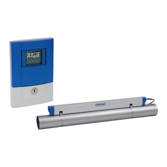
Ultrasonic clamp-on flowmeter
Hide thumbs
Also See for OPTISONIC 6300:
- Handbook (212 pages) ,
- Manual (60 pages) ,
- Quick start manual (56 pages)

Related Manuals for KROHNE OPTISONIC 6300


Summary of Contents for KROHNE OPTISONIC 6300
- Page 1 OPTISONIC 6300 OPTISONIC 6300 OPTISONIC 6300 OPTISONIC 6300 Quick Start Quick Start Quick Start Quick Start Ultrasonic clamp-on flowmeter ER 4.0.0_ © KROHNE 06/2019 - 4005857501 - QS OPTISONIC 6300 v2 R01 en...
-
Page 2: Table Of Contents
3.5 Signal cable to flow sensor .................... 35 3.6 Signal cable to converter ....................37 3.7 Modular inputs/outputs connections ................39 3.8 Inputs and outputs, overview ..................41 3.8.1 Description of the CG-number....................41 www.krohne.com 06/2019 - 4005857501 - QS OPTISONIC 6300 v2 R01 en... - Page 3 5.1 Dimensions and weight ....................53 5.1.1 Clamp-on sensor and splitter- (cable) box ................53 5.1.2 Mounting plate of field housing .................... 55 5.1.3 Mounting plate of wall-mounted housing ................55 06/2019 - 4005857501 - QS OPTISONIC 6300 v2 R01 en www.krohne.com...
-
Page 4: Safety Instructions
If you need to return the device to the manufacturer or supplier, please fill out the form • contained in the manual and send it with the device. Unfortunately, the manufacturer cannot repair or inspect the device without the completed form. www.krohne.com 06/2019 - 4005857501 - QS OPTISONIC 6300 v2 R01 en... -
Page 5: Installation
The OPTISONIC 6300 OPTISONIC 6300 OPTISONIC 6300 OPTISONIC 6300 is designed exclusively for bi-directional measurements on conductive and / or non-conductive fluids. Excess of contaminations (gas, particles, 2 phases) disturb the acoustic signal and thus must be avoided. The overall functionality of the OPTISONIC 6300... - Page 6 3 4 fixing units 4 Coupling pads 5 2 metal straps 6 Signal cable plus connector cap 7 Cable box plus signal cable INFORMATION! No special tools, no training required! www.krohne.com 06/2019 - 4005857501 - QS OPTISONIC 6300 v2 R01 en...
-
Page 7: Device Description
Product specific information and extensive product specification is available using PICK, the Product Information Center KROHNE web-tool. PICK can be found via the service menu button on the KROHNE.com website. Device versions The ultrasonic clamp-on flowmeter is available in different versions and with two separate flow converters (wall-mount or field version). -
Page 8: Overview Of The Nameplates (Examples)
5 Sensor serial number(s), corresponds with the number mentioned on type sticker 6 Manufacturing date and CE sign with number(s) of notified body/bodies 7 Type designation of the flowmeter with CG number 8 Name and address of the manufacturer www.krohne.com 06/2019 - 4005857501 - QS OPTISONIC 6300 v2 R01 en... -
Page 9: Nameplate For The Measuring Sensor
3 Tag number 4 CE sign with number(s) of notified body/bodies 5 Media temperature and calibration data 6 Type designation of the flowmeter 7 Name and address of the manufacturer 06/2019 - 4005857501 - QS OPTISONIC 6300 v2 R01 en www.krohne.com... -
Page 10: Example Of Io Nameplate
• Storage temperature -50...+70°C / -58...+158°F 2.6 Transport Signal converter • Do not lift the signal converter by the cable glands. Measuring sensor • Do not lift the measuring sensor by the connected cables. www.krohne.com 06/2019 - 4005857501 - QS OPTISONIC 6300 v2 R01 en... -
Page 11: Pre-Installation Requirements
Additionally, flow profile distortion is possible. CAUTION! If you program the diameter, please note that you use the outer diameter of the pipe. 06/2019 - 4005857501 - QS OPTISONIC 6300 v2 R01 en www.krohne.com... - Page 12 • of cloth. Coupling fat on the converter housing may be removed using soapy water. CAUTION! The device should be protected from corrosive chemicals or gases and dust/particles accumulation. www.krohne.com 06/2019 - 4005857501 - QS OPTISONIC 6300 v2 R01 en...
-
Page 13: Inlet, Outlet And Recommended Mounting Area
Always install the sensor at a non-insulated part of the pipe. Remove any insulation if • necessary! After installation, the sensor can be completely insulated. The sensor cable must be kept • away from the hot pipe surface. • Always wear protective gloves. 06/2019 - 4005857501 - QS OPTISONIC 6300 v2 R01 en www.krohne.com... -
Page 14: Long Horizontal Pipes
INFORMATION! 2 dimensional bends occur in a vertical or or or or horizontal plane (X/Y) only, while 3 dimensional bends occur in both vertical and and horizontal plane (X/Y/Z). www.krohne.com 06/2019 - 4005857501 - QS OPTISONIC 6300 v2 R01 en... -
Page 15: T-Section
INSTALLATION OPTISONIC 6300 2.8.4 T-section Figure 2-12: Distance behind a T-section 20 DN 2.8.5 Bends Figure 2-13: Installation in bending pipes Figure 2-14: Installation in bending pipes 06/2019 - 4005857501 - QS OPTISONIC 6300 v2 R01 en www.krohne.com... -
Page 16: Open Feed Or Discharge
2.8.8 Position of control valve Always install control valves downstream of the flowmeter in order to avoid cavitation or distortion of the flow profile. Figure 2-17: Position of control valve www.krohne.com 06/2019 - 4005857501 - QS OPTISONIC 6300 v2 R01 en... -
Page 17: Pipe Diameters And Sensor Construction
Large: V mode (2 traverses) Table 2-1: Version and preferred measuring mode 2.8.10 Pipe and media parameters INFORMATION! Detailed databases of most pipe and media parameters are on the supplied CD. 06/2019 - 4005857501 - QS OPTISONIC 6300 v2 R01 en www.krohne.com... -
Page 18: Installation Of The Flowmeter
• 5 return the other end of the metal strap through the upper strap lock on both the side of the sensor rail 2. • 6 tighten and lock the strap locks with an Allen wrench. Both sides from sensor rail are secured on the piping 7. www.krohne.com 06/2019 - 4005857501 - QS OPTISONIC 6300 v2 R01 en... - Page 19 • 4 put grease on the contact surfaces of the transducers. • 5 put back cover by tilting back in a 90° angle. • 6 press the cover back vertically on the locking strips until you hear them click. 06/2019 - 4005857501 - QS OPTISONIC 6300 v2 R01 en www.krohne.com...
-
Page 20: Installation Of Solid Contact Material
Apply a thin layer of grease on both sides of the pad and place it on the transducer surface. Click and turn the rail back on the pipe. www.krohne.com 06/2019 - 4005857501 - QS OPTISONIC 6300 v2 R01 en... - Page 21 • 6 put back sensor rail by tilting back in a 90° angle. • 7 press the sensor rail back vertically on the fixing units until you hear them click. 06/2019 - 4005857501 - QS OPTISONIC 6300 v2 R01 en www.krohne.com...
-
Page 22: Installation Instructions For Small And Medium Version
Figure 2-19: Procedure for installation of small or medium version 1 Rail, small version 2 Rail, medium version 3 Choose for V-mode or ... 4 Choose for W-mode 5 Make settings in converter www.krohne.com 06/2019 - 4005857501 - QS OPTISONIC 6300 v2 R01 en... - Page 23 2 Single pipe/dual path version 3 Dual pipe/single path version 4 Single pipe/dual path in "X Mode" INFORMATION! Refer to the manual of the OPTISONIC 6300 for more information regarding "X mode". 06/2019 - 4005857501 - QS OPTISONIC 6300 v2 R01 en www.krohne.com...
-
Page 24: Mechanical Installation Of Large Version
5 Mount the cable box (only for the downstream metal strap). 6 Push the metal strap through the upper slot of the fixing unit. 7 Pull the metal strap moderately tight by hand. • Secure by turning screws clockwise. www.krohne.com 06/2019 - 4005857501 - QS OPTISONIC 6300 v2 R01 en... -
Page 25: Mounting The Down Rail
1 Enter the values for the installation menu, X1...X7.2.8 2 Read the advised mounting distance in menu X7.2.3 3 Choose for Z-mode (default) or 4 Choose for V-mode Finish the installation menu 06/2019 - 4005857501 - QS OPTISONIC 6300 v2 R01 en www.krohne.com... - Page 26 44 or Start measurement of large version on page 46. INFORMATION! Information and details for the mechanical installation refer to the manual of the OPTISONIC 6300 and for the electrical connections refer to Electrical connections signal converter on page 32 www.krohne.com...
-
Page 27: Mounting The Field Housing, Remote Version
Figure 2-24: Pipe mounting of the field housing 1 Fix the signal converter to the pipe. 2 Fasten the signal converter using standard U-bolts and washers. 3 Tighten the nuts. 06/2019 - 4005857501 - QS OPTISONIC 6300 v2 R01 en www.krohne.com... -
Page 28: Wall Mounting
4 Screw the signal converter to the mounting plate with the nuts and washers. Figure 2-26: Mounting multiple devices next to each other a 600 mm / 23.6" b 250 mm / 9.8" www.krohne.com 06/2019 - 4005857501 - QS OPTISONIC 6300 v2 R01 en... - Page 29 2 Fasten the mounting plate securely to the wall. 3 Screw the signal converter to the mounting plate with the nuts and washers. Figure 2-28: Mounting multiple devices next to each other a 240 mm / 9.4" 06/2019 - 4005857501 - QS OPTISONIC 6300 v2 R01 en www.krohne.com...
-
Page 30: Turning The Display Of The Field Housing Version
Each time a housing cover is opened, the thread should be cleaned and greased. Use only resin- free and acid-free grease. Ensure that the housing gasket is properly fitted, clean and undamaged. www.krohne.com 06/2019 - 4005857501 - QS OPTISONIC 6300 v2 R01 en... -
Page 31: Electrical Connections
2 Tighten the screw connection of the cable entry securely. 3 Never mount the housing with the cable entries facing upwards. 4 Seal cable entries that are not needed with a plug. 06/2019 - 4005857501 - QS OPTISONIC 6300 v2 R01 en www.krohne.com... -
Page 32: Electrical Connections Signal Converter
WARNING! This is a Class A product. In a domestic environment this product may cause radio interference in which case the user may be required to take adequate measures. www.krohne.com 06/2019 - 4005857501 - QS OPTISONIC 6300 v2 R01 en... -
Page 33: Power Supply
PE of the power supply must be connected to the separate U- clamp terminal in the terminal compartment of the signal converter. INFORMATION! 240 VAC+5% is included in the tolerance range. 06/2019 - 4005857501 - QS OPTISONIC 6300 v2 R01 en www.krohne.com... -
Page 34: Signal Converter Power Supply Connections
3.4.1 Signal converter power supply connections Field version (L+) / L (L-) / N Figure 3-5: Signal converter field version, power supply connections Wall version Figure 3-6: Signal converter wall version, power supply www.krohne.com 06/2019 - 4005857501 - QS OPTISONIC 6300 v2 R01 en... -
Page 35: Signal Cable To Flow Sensor
For XT versions: check if the signal cable is heat protected with the protection sleeve of 1 meter / 40". INFORMATION! The signal cable delivered with the device has to be connected correctly with a minimum bending radius of 100 mm / 4 ” 06/2019 - 4005857501 - QS OPTISONIC 6300 v2 R01 en www.krohne.com... - Page 36 To ensure smooth functioning, always use the signal cable(s) included in the delivery. CAUTION! When installing the EMC gland, make sure that the shield of the cable has a good contact with the internal metalised insert of the EMC gland. www.krohne.com 06/2019 - 4005857501 - QS OPTISONIC 6300 v2 R01 en...
-
Page 37: Signal Cable To Converter
Excessive dis- / re-connection and/or positioning the connectors skewed to each other will damage the inside clips of the connectors. This results in an improper contact and measurement errors. 06/2019 - 4005857501 - QS OPTISONIC 6300 v2 R01 en www.krohne.com... - Page 38 Figure 3-13: Inserting cable and secure with clamp on shielding bush 1 Connection compartiment sensor cable(s) 2 Grounding clamp with metal shielding bush of sensor cable Wall version Figure 3-14: Connect signal cable www.krohne.com 06/2019 - 4005857501 - QS OPTISONIC 6300 v2 R01 en...
-
Page 39: Modular Inputs/Outputs Connections
• Open the housing cover 1 and remove. • Push the prepared cable through the cable entry and connect the necessary conductors 2. • Connect the shield if necessary 3. 06/2019 - 4005857501 - QS OPTISONIC 6300 v2 R01 en www.krohne.com... - Page 40 • Push the prepared cable through the cable entry 2 and connect the necessary conductors 3. • Connect the shield if necessary 4. • Close the cover of the terminal compartment. • Lock 5 the housing cover with screw driver (counter clockwise). www.krohne.com 06/2019 - 4005857501 - QS OPTISONIC 6300 v2 R01 en...
-
Page 41: Inputs And Outputs, Overview
EN 60947-5-6. Errors indicated on LC display. Error messages possible via status output. Active current input Passive current input 2 x IIn Two active current inputs (for Ex i I/O) No additional module installed No further module possible 06/2019 - 4005857501 - QS OPTISONIC 6300 v2 R01 en www.krohne.com... -
Page 42: Fixed, Non-Alterable Input/Output Versions
1 Function changed by reconnecting 2 Changeable • The grey boxes in the tables denote unassigned or unused connection terminals. • Connection terminal A+ is only operable in the basic input/output version. www.krohne.com 06/2019 - 4005857501 - QS OPTISONIC 6300 v2 R01 en... -
Page 43: Alterable Input/Output Versions
Modbus (option) G _ _ max. 2 optional modules for term. A + B Common Sign. B Sign. A (D1) (D0) 1 Changeable 2 Not activated bus terminator 06/2019 - 4005857501 - QS OPTISONIC 6300 v2 R01 en www.krohne.com... -
Page 44: Start-Up
• Fill in the actual transducer distance at menu X7.2.6 (and X8.2.6 if applicable) • Run the optimization loop until the transducer distance changes no more than 0.5%. • www.krohne.com 06/2019 - 4005857501 - QS OPTISONIC 6300 v2 R01 en... -
Page 45: Start Measurement (Standard Setup)
2 paths: go to X4.2 for the 2 pipe. 2 pipes: go to X6 for the 2 X7.2.11: End Installation? Enter "Yes" to save the installation. The measurement screen will appear. Mount the cover. 06/2019 - 4005857501 - QS OPTISONIC 6300 v2 R01 en www.krohne.com... -
Page 46: Start Measurement Of Large Version
Proceed with the mechanical installation of the rails: refer to large version on page 24. After the mechanical installation of the rails, continue with the standard set up (configuration) refer to Start measurement (standard setup) on page 45. www.krohne.com 06/2019 - 4005857501 - QS OPTISONIC 6300 v2 R01 en... - Page 47 Figure 4-3: Device configurations for "Large" versions 1 Single pipe, single path with cable ≤ 5 m 2 Single pipe, single path with cable ≥ 10 m 3 Single pipe, dual path 4 Dual pipe 06/2019 - 4005857501 - QS OPTISONIC 6300 v2 R01 en www.krohne.com...
-
Page 48: Mechanical Installation For Large Version
5 Mount the cable box (only for the downstream metal strap). 6 Push the metal strap through the upper slot of the fixing unit. 7 Pull the metal strap moderately tight by hand. • Secure by turning screws clockwise. www.krohne.com 06/2019 - 4005857501 - QS OPTISONIC 6300 v2 R01 en... - Page 49 2 Add the Advised Distance and mark the location on the alignment line. • Mount the DOWN rail in such a way that the transducer is at the marked location. 06/2019 - 4005857501 - QS OPTISONIC 6300 v2 R01 en www.krohne.com...
- Page 50 It can be necessary to install the DOWN rail as shown below. Figure 4-8: Transducers almost opposite, distance small 1 The installation of the rails are (more or less) facing straight and metal straps are mounted close beside each other. www.krohne.com 06/2019 - 4005857501 - QS OPTISONIC 6300 v2 R01 en...
- Page 51 Figure 4-9: Mounting large version in V-mode 1 Fixing units 2 Reference marking 3 Cable box 4 Advised Distance, X7.4 5 Minimum distance between UP and DOWN rail: 110 mm / 4.3" 06/2019 - 4005857501 - QS OPTISONIC 6300 v2 R01 en www.krohne.com...
- Page 52 3 Make connections in splitter- (cable) box 4 Cable to converter 5 Turn the screws clockwise to secure the caps INFORMATION! See also the previous sections "Installation" and "Electrical connections". www.krohne.com 06/2019 - 4005857501 - QS OPTISONIC 6300 v2 R01 en...
-
Page 53: Technical Data
Medium - stainless steel / XT 32.4 Table 5-2: Dimensions and weight clamp-on sensor (inch - lb) 1 value for one of the 2 delivered rails 2 delivered without cover 06/2019 - 4005857501 - QS OPTISONIC 6300 v2 R01 en www.krohne.com... - Page 54 Table 5-3: Dimensions and weight splitter- (cable) box (mm - kg) Dimensions [inches] Approximately weight without cable [lbs] Cable box 4.53 8.27 2.64 Table 5-4: Dimensions and weight splitter- (cable) box (inch - lb) www.krohne.com 06/2019 - 4005857501 - QS OPTISONIC 6300 v2 R01 en...
-
Page 55: Mounting Plate Of Field Housing
Table 5-5: Dimensions in mm and inch 5.1.3 Mounting plate of wall-mounted housing Figure 5-4: Dimensions of mounting plate of wall-mounted housing [mm] [inch] Ø9 Ø0.4 3.85 Table 5-6: Dimensions in mm and inch 06/2019 - 4005857501 - QS OPTISONIC 6300 v2 R01 en www.krohne.com... - Page 56 • Process Analysis • Services Head Office KROHNE Messtechnik GmbH Ludwig-Krohne-Str. 5 47058 Duisburg (Germany) Tel.: +49 203 301 0 Fax: +49 203 301 10389 info@krohne.com The current list of all KROHNE contacts and addresses can be found at: www.krohne.com...
Need help?
Do you have a question about the OPTISONIC 6300 and is the answer not in the manual?
Questions and answers