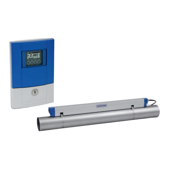
KROHNE OPTISONIC 6300 Quick Start Manual
Ultrasonic clamp-on flowmeter
Hide thumbs
Also See for OPTISONIC 6300:
- Handbook (212 pages) ,
- Manual (60 pages) ,
- Quick start manual (56 pages)

Related Manuals for KROHNE OPTISONIC 6300


Summary of Contents for KROHNE OPTISONIC 6300
- Page 1 OPTISONIC 6300 OPTISONIC 6300 OPTISONIC 6300 OPTISONIC 6300 Quick Start Quick Start Quick Start Quick Start Ultrasonic clamp-on flowmeter ER 3.4.0_ © KROHNE 07/2009 - 7.30959.24.00 - QS OPTISONIC 6300 R04 en...
-
Page 2: Table Of Contents
3.1 General instructions for programming................28 3.2 Start measurement of small / medium version ............32 3.3 Start measurement of large version................33 3.4 Mechanical installation for large version ..............35 www.krohne.com 07/2009 - 7.30959.24.00 - QS OPTISONIC 6300 R04 en... - Page 3 CONTENTS OPTISONIC 6300 4 Technical data 4.1 Technical data......................... 45 5 Notes 07/2009 - 7.30959.24.00 - QS OPTISONIC 6300 R04 en www.krohne.com...
-
Page 4: Installation
® 7 Mineral coupling grease (standard versions) or high temperature contactgel Pyrogel (XT versions) 8 Signal cable plus connector cap (XT versions have a protection sleeve around the signal cable). www.krohne.com 07/2009 - 7.30959.24.00 - QS OPTISONIC 6300 R04 en... -
Page 5: Overview
• Store the flowmeter in a dry and dust-free location. • Avoid lasting direct exposure to the sun. • Store the flowmeter in its original packing. 1.5 Transport No special requirements. 07/2009 - 7.30959.24.00 - QS OPTISONIC 6300 R04 en www.krohne.com... -
Page 6: Pre-Installation Requirements
Additionally flow profile distortion is possible. CAUTION! If you program the diameter, please note that you use the outer diameter of the pipe. www.krohne.com 07/2009 - 7.30959.24.00 - QS OPTISONIC 6300 R04 en... -
Page 7: Inlet, Outlet And Recommended Mounting Area
• If not possible, ensure adequate velocity to prevent air, gas or vapor from collecting in upper part. • In partially filled pipes, the clamp-on flowmeter will report incorrect flow rates, or not measure. Figure 1-4: Long horizontal pipes 07/2009 - 7.30959.24.00 - QS OPTISONIC 6300 R04 en www.krohne.com... -
Page 8: Open Feed Or Discharge
Figure 1-6: Down going pipeline over 5 m /16 ft length 1.7.5 Position of control valve Always install control valves downstream of flowmeter in order to avoid cavitation or distortion of flow profile. Figure 1-7: Position of control valve www.krohne.com 07/2009 - 7.30959.24.00 - QS OPTISONIC 6300 R04 en... -
Page 9: Position Of Pump
1.7.7 Pipe diameters and sensor construction Figure 1-9: Measuring modes 1 Z-mode 2 V-mode 3 W-mode 1.7.8 Pipe and media parameters INFORMATION! Detailed databases of most pipe and media parameters are on the supplied CD. 07/2009 - 7.30959.24.00 - QS OPTISONIC 6300 R04 en www.krohne.com... -
Page 10: Installation Of The Flowmeter
Installation of the rails with the metal straps Installation of the rails with the metal straps Installation of the rails with the metal straps • 8: Repeat steps 1...7 at the other side of the rail. www.krohne.com 07/2009 - 7.30959.24.00 - QS OPTISONIC 6300 R04 en... - Page 11 • Slide the transducer 2 to the advised mounting distance 3 (menu X9.4). • Lock the transducer by turning the locking knob 1 clockwise. Greasing the transducer surfaces Greasing the transducer surfaces Greasing the transducer surfaces Greasing the transducer surfaces 07/2009 - 7.30959.24.00 - QS OPTISONIC 6300 R04 en www.krohne.com...
-
Page 12: Installation Instructions For Small And Medium Version
Figure 1-10: Procedure for installation of small or medium version 1 Rail, small version 2 Rail, medium version 3 Choose for V-mode or ... 4 Choose for W-mode 5 Make settings in converter www.krohne.com 07/2009 - 7.30959.24.00 - QS OPTISONIC 6300 R04 en... - Page 13 3 Small version: single pipe / dual path 4 Medium version: single pipe / dual path 5 Small version: dual pipe / single path 6 Medium version: dual pipe / single path 07/2009 - 7.30959.24.00 - QS OPTISONIC 6300 R04 en www.krohne.com...
-
Page 14: Installation Instructions For Large Version
1 Enter the values for the installation menu, X1...X9.8.4 2 Read the advised mounting distance in menu X9.8.5 3 Choose for Z-mode (default) or ... 4 Choose for V-mode 5 Finish the installation menu www.krohne.com 07/2009 - 7.30959.24.00 - QS OPTISONIC 6300 R04 en... - Page 15 INSTALLATION OPTISONIC 6300 Figure 1-13: Device versions 1 Single pipe, single path 2 Single pipe, dual path 3 Dual pipe 07/2009 - 7.30959.24.00 - QS OPTISONIC 6300 R04 en www.krohne.com...
-
Page 16: Mounting Of Converter
Each time a housing cover is opened, the thread should be cleaned and greased. Use only resin- free and acid-free grease. Ensure that the housing gasket is properly fitted, clean and undamaged. www.krohne.com 07/2009 - 7.30959.24.00 - QS OPTISONIC 6300 R04 en... -
Page 17: Mounting Of Ufc 300 W
• Position lock washers and nuts on the housing bolts, tighten nuts slightly. • Align housing, tighten nuts firmly. • Observe max. allowed length of 30 m / 98.4 ft for the signal cable. 07/2009 - 7.30959.24.00 - QS OPTISONIC 6300 R04 en www.krohne.com... -
Page 18: Electrical Connections
2 Cover, terminal compartment for power supply and inputs/outputs 3 Cable entry for power 4 Cable entry for inputs/outputs 5 Cable entry for sensor cable 6 Cover, sensor terminal compartment www.krohne.com 07/2009 - 7.30959.24.00 - QS OPTISONIC 6300 R04 en... -
Page 19: Ufc 300 W
2 Cover for the three separate terminal compartments for power, sensor connection and inputs/outputs 3 Locking screw, 1/2 turn left/right to open/close cover 2 4 Sensor terminal compartment 5 Terminal compartment for inputs/outputs 6 Power terminal compartment, open separate shock-hazard protection cover 07/2009 - 7.30959.24.00 - QS OPTISONIC 6300 R04 en www.krohne.com... -
Page 20: Electrical Connection
1 Put in the connector. 2 Turn knob to secure the connector. CAUTION! For XT versions: check if the signal cable is heat protected with the protection sleeve of 1 meter / 40". www.krohne.com 07/2009 - 7.30959.24.00 - QS OPTISONIC 6300 R04 en... - Page 21 1 Connect the blue cable to the UP rail. 2 Connect the green cable to the DOWN rail. 3 Make connections in cable box. 4 Cable to converter 5 Turn the screws clockwise to secure the caps. 07/2009 - 7.30959.24.00 - QS OPTISONIC 6300 R04 en www.krohne.com...
-
Page 22: Signal Cable And Power Supply Signal Converter
1 Connect blue cable to 1U (to 2U for 2 sensor) and the green cable to 1D (2D for 2 sensor) 2 Communication I/O 3 Power supply: 24 VAC/DC or 100...240 VAC www.krohne.com 07/2009 - 7.30959.24.00 - QS OPTISONIC 6300 R04 en... - Page 23 U-clamp terminal in the terminal compartment of the signal converter. • When connecting to functional extra-low voltages, provide a facility for protective separation (PELV) (VDE 0100 / VDE 0106 and/or IEC 364 / IEC 536 or relevant national regulations). 07/2009 - 7.30959.24.00 - QS OPTISONIC 6300 R04 en www.krohne.com...
-
Page 24: Signal Cable To Converter
2 Tighten the screw connection of the cable entry securely. 3 Never mount the housing with the cable entries facing upwards. 4 Seal cable entries that are not needed with a plug. www.krohne.com 07/2009 - 7.30959.24.00 - QS OPTISONIC 6300 R04 en... -
Page 25: Inputs And Outputs, Overview
1 function changed by reconnection 2 changeable • The grey boxes in the tables denote unassigned or unused connection terminals. • Connection terminal A+ is only operable in the basic input/output version. 07/2009 - 7.30959.24.00 - QS OPTISONIC 6300 R04 en www.krohne.com... - Page 26 Signal converter monitors cable breaks and short circuits as per EN 60947-5-6. Errors indicated on LCD display. Error messages possible via status output. Active current input Passive current input No additional module installed No further module possible www.krohne.com 07/2009 - 7.30959.24.00 - QS OPTISONIC 6300 R04 en...
-
Page 27: Alterable Input/Output Versions
Signal converter monitors cable breaks and short circuits as per EN 60947-5-6. Errors indicated on LCD display. Error messages possible via status output. Active current input Passive current input No additional module installed No further module possible 07/2009 - 7.30959.24.00 - QS OPTISONIC 6300 R04 en www.krohne.com... -
Page 28: Start-Up
Esc (> + ↑) Return to menu mode Return to sub-menu or without acceptance of function without data acceptance of data www.krohne.com 07/2009 - 7.30959.24.00 - QS OPTISONIC 6300 R04 en... - Page 29 Start installation menu • Connect converter to power supply and power up converter. First and second page appear intermittently • Keep left button ">" pressed, until in display appears "release key now". 07/2009 - 7.30959.24.00 - QS OPTISONIC 6300 R04 en www.krohne.com...
- Page 30 > ↓ > fill in using ↑ ↓ > X6.13 viscosity > ↑ ↓ pipe data 2 > ↑ ↓ X7.1 copy pipe 1 data > start to copy ? www.krohne.com 07/2009 - 7.30959.24.00 - QS OPTISONIC 6300 R04 en...
- Page 31 (underneath X10 becomes active if two pipes or two paths (underneath X10 becomes active if two pipes or two paths are selected in X4 or X5) ↑ ↓ install transd. 2 > submenus identical to X9.1 up to X9.12 07/2009 - 7.30959.24.00 - QS OPTISONIC 6300 R04 en www.krohne.com...
-
Page 32: Start Measurement Of Small / Medium Version
• X9.12: End Installation? Enter "Yes" to save the installation. The measurement screen will appear. • Mount the cover (see the section "mounting the cover" in chapter "General mechanical installation") www.krohne.com 07/2009 - 7.30959.24.00 - QS OPTISONIC 6300 R04 en... -
Page 33: Start Measurement Of Large Version
• X9.7: Press enter • X9.8: Optimization loop. Enter "No" in X9.8.1 • X9.9: Press enter. Wait for 30 seconds • X9.10: Path ready? Enter "Yes" • X9.12: End Installation? Enter "Yes" 07/2009 - 7.30959.24.00 - QS OPTISONIC 6300 R04 en www.krohne.com... - Page 34 Advised distance [mm] Advised distance [mm] Transducer position [mm] Transducer position [mm] 100...250 >250 Figure 3-3: Device versions 1 Single pipe, single path 2 Single pipe, dual path 3 Dual pipe www.krohne.com 07/2009 - 7.30959.24.00 - QS OPTISONIC 6300 R04 en...
-
Page 35: Mechanical Installation For Large Version
Figure 3-4: Mounting the large rail 1 Align the UP rail with the pipeline. 2 Fixing units 3 Turn screws clockwise to secure. 4 Mark the position. 5 Cable box 07/2009 - 7.30959.24.00 - QS OPTISONIC 6300 R04 en www.krohne.com... - Page 36 5 Mount the cable box (only for downstream metal strap). 6 Push the metal strap through the upper slit of the fixing unit. 7 Pull the metal strap moderately tight by hand. • Secure by turning screws clockwise. www.krohne.com 07/2009 - 7.30959.24.00 - QS OPTISONIC 6300 R04 en...
- Page 37 2 Add the Advised Distance and mark the location on the alignment line. • Mount the DOWN rail in such a way that the transducer is at the marked location. 2. FIND THE LOCATION WITH THE SUPPLIED POSITIONING TOOL 07/2009 - 7.30959.24.00 - QS OPTISONIC 6300 R04 en www.krohne.com...
- Page 38 2 Outer diameter of pipeline INFORMATION! For large diameters you can use the weight of the metal plates to throw the cable around the pipe. First release one of the cables in that case! www.krohne.com 07/2009 - 7.30959.24.00 - QS OPTISONIC 6300 R04 en...
- Page 39 Repeat above steps to check if you find the same points. Figure 3-8: Marking the opposite location Calculate the middle of the alignment line between the 4 V-marks as shown. 07/2009 - 7.30959.24.00 - QS OPTISONIC 6300 R04 en www.krohne.com...
- Page 40 • Mount the DOWN rail in such a way that the transducer is at the marked location. • Grease all transducers, see "General mechanical installation". INFORMATION! It can be necessary to install the DOWN rail as shown below. www.krohne.com 07/2009 - 7.30959.24.00 - QS OPTISONIC 6300 R04 en...
- Page 41 Figure 3-10: Mounting large version in V-mode 1 Fixing units 2 Reference marking 3 Cable box 4 Advised Distance, X9.4 5 Minimum distance between UP and DOWN rail: 110 mm / 4.3" 07/2009 - 7.30959.24.00 - QS OPTISONIC 6300 R04 en www.krohne.com...
- Page 42 1 Connect blue cable to 1U (to 2U for 2 sensor) and the green cable to 1D (2D for 2 sensor) 2 Communication I/O 3 Power supply: 24 VAC/DC or 100...240 VAC www.krohne.com 07/2009 - 7.30959.24.00 - QS OPTISONIC 6300 R04 en...
- Page 43 Signal < 10%: Signal < 10%: Signal < 10%: Signal < 10%: bad or no signal, check settings in menu X6, increase transducer distance and/or go into the optimization loop. 07/2009 - 7.30959.24.00 - QS OPTISONIC 6300 R04 en www.krohne.com...
- Page 44 • X9.12: End Installation? If you enter "No" the installation is not saved, go to X9. If you enter "Yes" the installation is saved and the measurement screen will appear. • Mount the cover (see section "mounting the cover" in chapter "General mechanical installation") www.krohne.com 07/2009 - 7.30959.24.00 - QS OPTISONIC 6300 R04 en...
- Page 45 2 internal counters with a max. of 8 counter places (e.g. for counting volume and/or mass units) Self diagnostics Integrated verification, diagnosis functions: flowmeter, process, measured value, empty pipe detection, bargraph 07/2009 - 7.30959.24.00 - QS OPTISONIC 6300 R04 en www.krohne.com...
- Page 46 Metal, plastic, ceramic, asbestos cement, internal / external coated pipes (coatings and liners fully bonded to pipe wall) Pipewall thickness < 200 mm / 7.87" Liner thickness < 20 mm / 0.79" www.krohne.com 07/2009 - 7.30959.24.00 - QS OPTISONIC 6300 R04 en...
- Page 47 2 internal triax, available lengths: 5 m / 15 ft (standard), maximum length 30 m / 90 ft Cable entries Standard: M20 x 1.5 Option: ½" NPT, PF ½ 07/2009 - 7.30959.24.00 - QS OPTISONIC 6300 R04 en www.krohne.com...
- Page 48 ≥ 250 Ω Load Please observe maximum value for current output Multidrop Yes, current output = 4 mA Multidrop addresses programmable in menu 1...15 Device drivers FDT/DTM www.krohne.com 07/2009 - 7.30959.24.00 - QS OPTISONIC 6300 R04 en...
- Page 49 = 0.6 mA open: I = 0.43 mA closed: I = 3.8 mA closed: I = 4.5 mA = 30 V = 100 mA = 1 W =10 nF ~ 0 mH 07/2009 - 7.30959.24.00 - QS OPTISONIC 6300 R04 en www.krohne.com...
- Page 50 = 0.6 mA open: I = 0.43 mA closed: I = 3.8 mA closed: I = 4.5 mA = 30 V = 100 mA = 1 W =10 nF = 0 mH www.krohne.com 07/2009 - 7.30959.24.00 - QS OPTISONIC 6300 R04 en...
- Page 51 Can be set together for all flow indicators and outputs, or separately for: current, pulse and frequency output, and for limit switches and the 3 internal counters Time setting 0…100 seconds, settable in 0.1 second steps 07/2009 - 7.30959.24.00 - QS OPTISONIC 6300 R04 en www.krohne.com...
- Page 52 Other approvals and standards Other approvals and standards Other approvals and standards Electromagnetic compatibility Directive: 89/336/EEC, NAMUR NE21/04 Harmonized standard: EN 61326-1: 2006 Low Voltage Directive Directive: 2006/95/EC Harmonized standard: EN 61010: 2001 www.krohne.com 07/2009 - 7.30959.24.00 - QS OPTISONIC 6300 R04 en...
- Page 53 NOTES OPTISONIC 6300 07/2009 - 7.30959.24.00 - QS OPTISONIC 6300 R04 en www.krohne.com...
- Page 54 NOTES OPTISONIC 6300 www.krohne.com 07/2009 - 7.30959.24.00 - QS OPTISONIC 6300 R04 en...
- Page 55 NOTES OPTISONIC 6300 07/2009 - 7.30959.24.00 - QS OPTISONIC 6300 R04 en www.krohne.com...
- Page 56 Measuring systems for sea-going tankers Head Office KROHNE Messtechnik GmbH & Co. KG Ludwig-Krohne-Str. 5 D-47058 Duisburg (Germany) Tel.:+49 (0)203 301 0 Fax:+49 (0)203 301 10389 info@krohne.de The current list of all KROHNE contacts and addresses can be found at: www.krohne.com...
Need help?
Do you have a question about the OPTISONIC 6300 and is the answer not in the manual?
Questions and answers