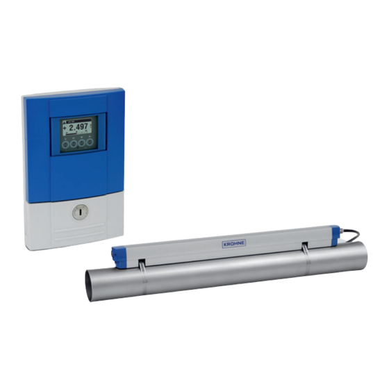
KROHNE OPTISONIC 6300 Handbook
Ultrasonic clamp-on flowmeter for liquids
Hide thumbs
Also See for OPTISONIC 6300:
- Handbook (120 pages) ,
- Manual (60 pages) ,
- Quick start manual (56 pages)

Related Manuals for KROHNE OPTISONIC 6300


Summary of Contents for KROHNE OPTISONIC 6300
- Page 1 OPTISONIC 6300 OPTISONIC 6300 OPTISONIC 6300 OPTISONIC 6300 Handbook Handbook Handbook Handbook Ultrasonic clamp-on flowmeter for liquids ER 4. © KROHNE 10/2020 - 4006193902 - HB OPTISONIC 6300 V2 R02 en...
- Page 2 All rights reserved. It is prohibited to reproduce this documentation, or any part thereof, without the prior written authorisation of KROHNE Messtechnik GmbH. Subject to change without notice. Copyright 2020 by KROHNE Messtechnik GmbH - Ludwig-Krohne-Str. 5 - 47058 Duisburg (Germany) www.krohne.com 10/2020 - 4006193902 - HB OPTISONIC 6300 V2 R02 en...
-
Page 3: Table Of Contents
3.7.6 Open feed or discharge......................26 3.7.7 Position of pump ........................27 3.7.8 Position of control valve......................27 3.7.9 Pipe diameters and sensor rail(s) construction..............28 3.7.10 Pipe and media parameters ....................28 10/2020 - 4006193902 - HB OPTISONIC 6300 V2 R02 en www.krohne.com... - Page 4 4.10.3 Basic inputs/outputs ......................73 4.10.4 Modular inputs/outputs and bus systems ................76 4.10.5 Ex i inputs/outputs ......................84 4.10.6 Current input active or passive................... 88 ® 4.10.7 HART connection ......................91 www.krohne.com 10/2020 - 4006193902 - HB OPTISONIC 6300 V2 R02 en...
- Page 5 6.4.12 Dual phase pulse output ....................140 6.4.13 Timeouts in programming mode ..................140 6.4.14 Function 5: Reynolds linearisation ................... 141 6.4.15 Output hardware ....................... 141 6.5 Status messages and diagnostic information.............. 142 10/2020 - 4006193902 - HB OPTISONIC 6300 V2 R02 en www.krohne.com...
- Page 6 8.3 Dimensions and weight ....................183 8.3.1 Housing ..........................183 8.3.2 Clamp-on sensor rail ......................184 8.3.3 Mounting plate of field housing ..................186 8.3.4 Mounting plate of wall-mounted housing ................186 www.krohne.com 10/2020 - 4006193902 - HB OPTISONIC 6300 V2 R02 en...
- Page 7 9.9.3 HART Menu Tree PDM - Menu Bar and Working Window ..........201 9.9.4 Process Variables Root Menu..................... 202 9.9.5 Diagnostic Root Menu ......................202 9.9.6 Device Root Menu ....................... 203 9.9.7 Offline Root Menu ....................... 208 10 Notes 10/2020 - 4006193902 - HB OPTISONIC 6300 V2 R02 en www.krohne.com...
-
Page 8: Safety Instructions
Release date Electronic revision Changes and Documentation compatibility 2018-09 ER 4.0.0_ MA OPTISONIC 6300 R01 2020-01 ER 4.1.1_ MA OPTISONIC 6300 R02 Table 1-2: Changes and effect on compatibility www.krohne.com 10/2020 - 4006193902 - HB OPTISONIC 6300 V2 R02 en... -
Page 9: Intended Use
OPTISONIC 6300 OPTISONIC 6300 OPTISONIC 6300 is designed exclusively as a clamp-on flowmeter for uni- or bidirectional measurements of liquid flows. Contaminations, like entrained gas, particles, 2 phase and non- homegeneous mixtures, can affect the acoustic signal and has to be avoided. -
Page 10: Safety Instructions From The Manufacturer
The manufacturer reserves the right to alter the content of its documents, including this disclaimer in any way, at any time, for any reason, without prior notification, and will not be liable in any way for possible consequences of such changes. www.krohne.com 10/2020 - 4006193902 - HB OPTISONIC 6300 V2 R02 en... -
Page 11: Product Liability And Warranty
This document is provided to help you establish operating conditions, which will permit safe and efficient use of this device. Special considerations and precautions are also described in the document, which appear in the form of icons as shown below. 10/2020 - 4006193902 - HB OPTISONIC 6300 V2 R02 en www.krohne.com... -
Page 12: Warnings And Symbols Used
In general, devices from the manufacturer may only be installed, commissioned, operated and maintained by properly trained and authorized personnel. This document is provided to help you establish operating conditions, which will permit safe and efficient use of this device. www.krohne.com 10/2020 - 4006193902 - HB OPTISONIC 6300 V2 R02 en... -
Page 13: Device Description
6 Coupling pads INFORMATION! Assembly materials and tools are not part of the delivery. Use the assembly materials and tools in compliance with the applicable occupational health and safety directives. 10/2020 - 4006193902 - HB OPTISONIC 6300 V2 R02 en www.krohne.com... - Page 14 • GDC interface set • Coupling grease; mineral (standard versions) or high-temperature contact (XT versions) • Coupling pads • Cable (splitter) box with signal cable INFORMATION! No special tools, no training required! www.krohne.com 10/2020 - 4006193902 - HB OPTISONIC 6300 V2 R02 en...
-
Page 15: Device Description
Product specific information and extensive product specification is available using PICK, the Product Information Center KROHNE web-tool. PICK can be found via the service menu button on the KROHNE.com website. Figure 2-3: System configuration possibilities 1 Single path, small or medium sensor rail... -
Page 16: Field Housing
4 Terminal compartment for power supply with safety cover (shock-hazard protection) 5 Cable entry for signal cable 6 Cable entry for inputs and outputs 7 Cable entry for power supply www.krohne.com 10/2020 - 4006193902 - HB OPTISONIC 6300 V2 R02 en... -
Page 17: Nameplates
4 Sensor serial number(s), corresponds with the number mentioned on type sticker 5 Electronic Revision number 6 Mains supply data 7 Data matrix 8 Protection category and Tag number 9 Ambient temperature 10/2020 - 4006193902 - HB OPTISONIC 6300 V2 R02 en www.krohne.com... -
Page 18: Example Nameplate Of The Flow Sensor Rail
2 Type designation and manufacturing date of the flowmeter 3 Media temperature and calibration data 4 Data matrix 5 Tag number 6 Protection category 7 Ambient temperature operating range 8 CE sign with number(s) of notified body/bodies www.krohne.com 10/2020 - 4006193902 - HB OPTISONIC 6300 V2 R02 en... -
Page 19: Example Of Io Nameplate
• A = active mode; the signal converter supplies the power for connection of the subsequent devices • P = passive mode; external power supply required for operation of the subsequent devices • N/C = connection terminals not connected 10/2020 - 4006193902 - HB OPTISONIC 6300 V2 R02 en www.krohne.com... -
Page 20: Installation
• Do not lift the measuring sensor rail(s), by the connected cables. • Make sure the fixing (strapping) units are correctly attached in locked position to prevent moving or loose parts of the sensor rail. www.krohne.com 10/2020 - 4006193902 - HB OPTISONIC 6300 V2 R02 en... -
Page 21: Pre-Installation Requirements
Additionally, flow profile distortion is possible. CAUTION! If you program the diameter, please note that you use the outer diameter of the pipe. 10/2020 - 4006193902 - HB OPTISONIC 6300 V2 R02 en www.krohne.com... - Page 22 Coupling grease on the converter housing may be removed using soapy water. CAUTION! The device should be protected from corrosive chemicals or gases and dust/particles accumulation. www.krohne.com 10/2020 - 4006193902 - HB OPTISONIC 6300 V2 R02 en...
-
Page 23: Installation Conditions
After installation, the sensor can be completely insulated. The signal cable must be protected • correctly and kept away from the hot pipe surface. Always use the correct Personal Protective Equipment (heat-protection, gloves). • 10/2020 - 4006193902 - HB OPTISONIC 6300 V2 R02 en www.krohne.com... -
Page 24: Horizontal (Long) Pipes
INFORMATION! 2 dimensional bends occur in a vertical or or or or horizontal plane (X/Y) only, while 3 dimensional bends occur in both vertical and and horizontal plane (X/Y/Z). www.krohne.com 10/2020 - 4006193902 - HB OPTISONIC 6300 V2 R02 en... -
Page 25: T-Section
Installation at the highest point will enlarge the risk of flowmeter malfunction, because of air/gas bubbles. Vertical installation in combination with an open surcharge has to be avoided. Vertical installation with a controlled back-pressure is possible. 10/2020 - 4006193902 - HB OPTISONIC 6300 V2 R02 en www.krohne.com... -
Page 26: Open Feed Or Discharge
3.7.6 Open feed or discharge Figure 3-7: Open feed or discharge Install the flowmeter on a lowered section of the pipeline to ensure a full pipe condition through the meter. www.krohne.com 10/2020 - 4006193902 - HB OPTISONIC 6300 V2 R02 en... -
Page 27: Position Of Pump
Recommended position to install a flowmeter is upstream a control valve. A clamp-on flowmeter can be installed downstream of the control valve if there is no cavitation in the pipeline system (e.g. flow profile disturbances are resolved). 10/2020 - 4006193902 - HB OPTISONIC 6300 V2 R02 en www.krohne.com... -
Page 28: Pipe Diameters And Sensor Rail(S) Construction
Table 3-1: Version and preferred measuring mode 3.7.10 Pipe and media parameters INFORMATION! Detailed databases of most pipe and media parameters are available. Contact Product Support or check the manufacturer website. www.krohne.com 10/2020 - 4006193902 - HB OPTISONIC 6300 V2 R02 en... -
Page 29: Installation Of The Sensor Rail
• 5 return the other end of the metal strap through the upper strap lock on both the side of the sensor rail 2. • 6 tighten and lock the strap locks with an Allen wrench or screwdriver. Both sides from sensor rail are secured on the piping 7. 10/2020 - 4006193902 - HB OPTISONIC 6300 V2 R02 en www.krohne.com... - Page 30 • 4 put coupling grease on the contact surfaces of the transducers. • 5 put back cover by tilting back in a 90° angle. • 6 press the cover back vertically on the locking strips until you hear them click. www.krohne.com 10/2020 - 4006193902 - HB OPTISONIC 6300 V2 R02 en...
-
Page 31: Installation Of Solid Contact Material
• 6 put back sensor rail by tilting back in a 90° angle. • 7 press the sensor rail back vertically on the fixing units until you hear them click. 10/2020 - 4006193902 - HB OPTISONIC 6300 V2 R02 en www.krohne.com... -
Page 32: Standard Installation Options
3.8.3 Standard installation options Single and dual path configuration The OPTISONIC 6300 flowmeter uses the UFC 300 ultrasonic signal converter which is designed to control one or two measuring paths continuously. The two paths can be used as a dual path measurement on a single pipe for maximum reliability, or as two flowmeters on two separate pipes for maximum flexibility. -
Page 33: Installation Instructions For Small And Medium Sensor Rail(S)
Figure 3-13: Procedure for installation of small or medium sensor rail 1 Small sensor rail 2 Medium sensor rail 3 Choose for V-mode or ... 4 Choose for W-mode 5 Make settings in converter 10/2020 - 4006193902 - HB OPTISONIC 6300 V2 R02 en www.krohne.com... -
Page 34: Mechanical Installation Of Large Version
1 Align the UP rail with the pipeline. 2 Optional fixing units for large diameters 3 Turn screws clockwise to secure. 4 Mark the position. 5 Optional cable (splitter) box www.krohne.com 10/2020 - 4006193902 - HB OPTISONIC 6300 V2 R02 en... - Page 35 5 Possible installation position cable (splitter) box 6 Push the metal strap through the upper slot of the fixing unit. 7 Pull the metal strap moderately tight by hand. • Secure by turning screws clockwise. 10/2020 - 4006193902 - HB OPTISONIC 6300 V2 R02 en www.krohne.com...
-
Page 36: Installing The Down Sensor Rail In V-Mode
• Always use coupling grease/pads, refer to on page 29. INFORMATION! Continue with the instructions as described in the section refer to General instructions for programming on page 92 www.krohne.com 10/2020 - 4006193902 - HB OPTISONIC 6300 V2 R02 en... -
Page 37: Installation Of The Down Sensor Rail
2 Add the Advised Distance and mark the location on the alignment line. • Mount the DOWN sensor rail in such a way that the transducer is at the marked location. 10/2020 - 4006193902 - HB OPTISONIC 6300 V2 R02 en www.krohne.com... -
Page 38: Determine The Transducer Position With A Paper Roll
• Fold the paper exactly in half 1 • Put the folded paper back and fit it tightly on the pipe 2 Figure 3-20: Fold paper and place back on pipe line www.krohne.com 10/2020 - 4006193902 - HB OPTISONIC 6300 V2 R02 en... - Page 39 Mark C is the perpendicular line with respect to the lines A and B. • After marking the lines: Determine with horizontal lines A/B and the vertical line C, the position of the sensor rails and transducers and place them accordingly 10/2020 - 4006193902 - HB OPTISONIC 6300 V2 R02 en www.krohne.com...
-
Page 40: Installing The Down Sensor Rail In Z-Mode
• Always use coupling grease/pads, refer to General mechanical installation on page 29. INFORMATION! Continue with the instructions as described in the section refer to General instructions for programming on page 92 www.krohne.com 10/2020 - 4006193902 - HB OPTISONIC 6300 V2 R02 en... -
Page 41: Configuration Instructions For Large Sensor Rail(S)
For information and details on the mechanical installation; refer to General notes on installation on page 20 Electrical connections signal converter on and for the electrical connections, refer to page 53 10/2020 - 4006193902 - HB OPTISONIC 6300 V2 R02 en www.krohne.com... -
Page 42: Installation Instructions For X Mode Configuration
• Set menu item X7.4 = transducer distance the exact distance between up transducer of Ta to the down transducer of Tb • Repeat the process for transducer 2 www.krohne.com 10/2020 - 4006193902 - HB OPTISONIC 6300 V2 R02 en... -
Page 43: Installation Of The Converter
Figure 3-26: Pipe mounting of the field housing 1 Fix the signal converter to the pipe. 2 Fasten the signal converter using standard U-bolts and washers. 3 Tighten the nuts. 10/2020 - 4006193902 - HB OPTISONIC 6300 V2 R02 en www.krohne.com... -
Page 44: Wall Mounting
4 Screw the signal converter to the mounting plate with the nuts and washers. Figure 3-28: Mounting multiple devices next to each other a 600 mm / 23.6" b 250 mm / 9.8" www.krohne.com 10/2020 - 4006193902 - HB OPTISONIC 6300 V2 R02 en... - Page 45 2 Fasten the mounting plate securely to the wall. 3 Screw the signal converter to the mounting plate with the nuts and washers. Figure 3-30: Mounting multiple devices next to each other a 240 mm / 9.4" 10/2020 - 4006193902 - HB OPTISONIC 6300 V2 R02 en www.krohne.com...
-
Page 46: Turning The Display Of The Field Housing Version
Each time a housing cover is opened, the thread should be cleaned and greased. Use only resin- free and acid-free grease. Ensure that the housing gasket is properly fitted, clean and undamaged. www.krohne.com 10/2020 - 4006193902 - HB OPTISONIC 6300 V2 R02 en... -
Page 47: Installation For Energy Measurement
The specific type must be suitable for proper use with the 4...20 mA current input of the I/O connections of the UFC 300 signal converter. 10/2020 - 4006193902 - HB OPTISONIC 6300 V2 R02 en www.krohne.com... -
Page 48: Program The Converter For Energy Measurement
The "Extended range A/B 0% and 100%" are meant for an alarm function. If a value is measured that is lower than the "Extended range A/B 0%" value or higher than the "Extended range A/B 100%" value, a warning "Over range xx" will appear. www.krohne.com 10/2020 - 4006193902 - HB OPTISONIC 6300 V2 R02 en... -
Page 49: Program The Process Input
In case the function is "Heating", the temperature at the "supply" side is the highest. In case the function is "Cooling", the temperature at the "supply" side is the lowest. 10/2020 - 4006193902 - HB OPTISONIC 6300 V2 R02 en www.krohne.com... -
Page 50: Program The Totalisers
• Select "+ counter" for only counting positive energy flows. • Select "- counter" for only counting negative energy flows. • At the "Measurement" option, select "Power". The energy value counter unit is kJ. www.krohne.com 10/2020 - 4006193902 - HB OPTISONIC 6300 V2 R02 en... -
Page 51: Start Measurement
907 kg) of ice. 1 kilo calorie per second Amount of heat required to increase 1 kg of 4187 water with 1 degree Celsius. 1 therm Equal to 100000 BTU 105506000 10/2020 - 4006193902 - HB OPTISONIC 6300 V2 R02 en www.krohne.com... -
Page 52: Electrical Connections
2 Tighten the screw connection of the cable entry securely. 3 Never mount the housing with the cable entries facing upwards. 4 Seal cable entries that are not needed with a plug. www.krohne.com 10/2020 - 4006193902 - HB OPTISONIC 6300 V2 R02 en... -
Page 53: Electrical Connections Signal Converter
WARNING! This is a Class A product. In a domestic environment this product may cause radio interference in which case the user may be required to take adequate measures. 10/2020 - 4006193902 - HB OPTISONIC 6300 V2 R02 en www.krohne.com... -
Page 54: Power Supply
PE of the power supply must be connected to the separate U- clamp terminal in the terminal compartment of the signal converter. INFORMATION! 240 VAC+5% is included in the tolerance range. www.krohne.com 10/2020 - 4006193902 - HB OPTISONIC 6300 V2 R02 en... -
Page 55: Signal Converter Power Supply Connections
4.4.1 Signal converter power supply connections Field version (L+) / L (L-) / N Figure 4-5: Signal converter field version, power supply connections Wall version Figure 4-6: Signal converter wall version, power supply 10/2020 - 4006193902 - HB OPTISONIC 6300 V2 R02 en www.krohne.com... -
Page 56: Example Of Connecting The Cable Extension (Splitter) Box
3 Installed DOWN rail 4 Extension cable to UFC 300 signal converter CAUTION! To ensure smooth functioning and safe instrument usage, always use the signal cable(s) included in the delivery. www.krohne.com 10/2020 - 4006193902 - HB OPTISONIC 6300 V2 R02 en... -
Page 57: Signal Cable To Converter
Continuously re-connection and/or positioning the connectors skewed to each other will damage the inside clips of the connectors, causing incorrect contact and measurement errors. 10/2020 - 4006193902 - HB OPTISONIC 6300 V2 R02 en www.krohne.com... - Page 58 1 path / 1 pipe Downstream U or 2.1 / Blue 2 path / 2 pipes Upstream D or 2.2 / Green 2 path / 2 pipes Downstream not connected not connected www.krohne.com 10/2020 - 4006193902 - HB OPTISONIC 6300 V2 R02 en...
- Page 59 U or 1.2 / Blue 2 path / 2 pipes Upstream D or 2.1 / Green 1 path / 1 pipe Downstream D or 2.2 / Green 2 path / 2 pipes Downstream 10/2020 - 4006193902 - HB OPTISONIC 6300 V2 R02 en www.krohne.com...
-
Page 60: Modular Inputs/Outputs Connections
For further information refer to Electrical connections signal converter on page 53 • For the electrical connection of bus systems refer to the separate documentation for the • respective bus systems. www.krohne.com 10/2020 - 4006193902 - HB OPTISONIC 6300 V2 R02 en... - Page 61 • Push the prepared cable through the cable entry 2 and connect the necessary conductors 3. • Connect the shield if necessary 4. • Close the cover of the terminal compartment. • Lock 5 the housing cover with screw driver (counter clockwise). 10/2020 - 4006193902 - HB OPTISONIC 6300 V2 R02 en www.krohne.com...
-
Page 62: Inputs And Outputs, Overview
• For hazardous areas, all of the input/output variants with terminal compartment in the Ex d (pressure-resistant casing) or Ex e (increased safety) versions can be delivered. • Please refer to the separate instructions for connection and operation of the Ex-devices. www.krohne.com 10/2020 - 4006193902 - HB OPTISONIC 6300 V2 R02 en... -
Page 63: Description Of The Cg-Number
EN 60947-5-6. Errors indicated on LC display. Error messages possible via status output. Active current input Passive current input 2 x IIn Two active current inputs (for Ex i I/O) No additional module installed No further module possible 10/2020 - 4006193902 - HB OPTISONIC 6300 V2 R02 en www.krohne.com... -
Page 64: Fixed, Non-Alterable Input/Output Versions
1 Function changed by reconnecting 2 Changeable • The grey boxes in the tables denote unassigned or unused connection terminals. • Connection terminal A+ is only operable in the basic input/output version. www.krohne.com 10/2020 - 4006193902 - HB OPTISONIC 6300 V2 R02 en... -
Page 65: Alterable Input/Output Versions
V/D- (1) Modbus (option) G _ _ max. 2 optional modules for term. A + B Common Sign. B Sign. A (D1) (D0) 1 Changeable 2 Not activated bus terminator 10/2020 - 4006193902 - HB OPTISONIC 6300 V2 R02 en www.krohne.com... -
Page 66: Description Of The Inputs And Outputs
• For information on the adjustable operating states refer to on page 116. DANGER! For devices used in hazardous areas, additional safety notes apply; please refer to the Ex documentation. www.krohne.com 10/2020 - 4006193902 - HB OPTISONIC 6300 V2 R02 en... -
Page 67: Current Output
For further information refer to Connection diagrams of inputs and outputs on page 71 and refer Technical data on page 172 DANGER! For devices used in hazardous areas, additional safety notes apply; please refer to the Ex documentation. 10/2020 - 4006193902 - HB OPTISONIC 6300 V2 R02 en www.krohne.com... -
Page 68: Pulse Output And Frequency Output
For further information refer to Connection diagrams of inputs and outputs on page 71 and refer Technical data on page 172 DANGER! For devices used in hazardous areas, additional safety notes apply; please refer to the Ex documentation. www.krohne.com 10/2020 - 4006193902 - HB OPTISONIC 6300 V2 R02 en... -
Page 69: Status Output And Limit Switch
For further information refer to Connection diagrams of inputs and outputs on page 71 DANGER! For devices used in hazardous areas, additional safety notes apply; please refer to the Ex documentation. 10/2020 - 4006193902 - HB OPTISONIC 6300 V2 R02 en www.krohne.com... -
Page 70: Current Input
For further information refer to Connection diagrams of inputs and outputs on page 71 and refer Technical data on page 172 DANGER! For devices used in hazardous areas, additional safety notes apply; please refer to the Ex documentation. www.krohne.com 10/2020 - 4006193902 - HB OPTISONIC 6300 V2 R02 en... -
Page 71: Connection Diagrams Of Inputs And Outputs
Signal converter monitors cable breaks and short circuits acc. to NAMUR EN 60947-5-6. Errors indicated on LC display. Error messages possible via status output. Current input active or passive 10/2020 - 4006193902 - HB OPTISONIC 6300 V2 R02 en www.krohne.com... -
Page 72: Description Of The Electrical Symbols
At frequencies above 100 Hz, shielded cables must be used to connect the counters. Internal resistance of the counter Button, N/O contact or similar Table 4-1: Description of the electrical symbols www.krohne.com 10/2020 - 4006193902 - HB OPTISONIC 6300 V2 R02 en... -
Page 73: Basic Inputs/Outputs
= 24 VDC nominal int, nom • U 32 VDC • I 22 mA • U 1.8 V • R ) / I Figure 4-17: Current output passive I 10/2020 - 4006193902 - HB OPTISONIC 6300 V2 R02 en www.krohne.com... - Page 74 ) / I L, min • Can also be set as status output; for the electrical connection refer to status output connection diagram. Figure 4-18: Pulse/frequency output passive P www.krohne.com 10/2020 - 4006193902 - HB OPTISONIC 6300 V2 R02 en...
- Page 75 = 2.8 mA • Can also be set as a status output; for the electrical connection refer to status output connection diagram. Figure 4-20: Control input passive C 1 Signal 10/2020 - 4006193902 - HB OPTISONIC 6300 V2 R02 en www.krohne.com...
-
Page 76: Modular Inputs/Outputs And Bus Systems
• R ) / I • X designates the connection terminals A, B or C, depending on the version of the signal converter. Figure 4-22: Current output passive I www.krohne.com 10/2020 - 4006193902 - HB OPTISONIC 6300 V2 R02 en... - Page 77 ) / I L, min • X designates the connection terminals A, B or D, depending on the version of the signal converter. Figure 4-23: Pulse/frequency output active P 10/2020 - 4006193902 - HB OPTISONIC 6300 V2 R02 en www.krohne.com...
- Page 78 • Can also be set as status output; refer to status output connection diagram. • X designates the connection terminals A, B or D, depending on the version of the signal converter. Figure 4-24: Pulse/frequency output passive P www.krohne.com 10/2020 - 4006193902 - HB OPTISONIC 6300 V2 R02 en...
- Page 79 • X designates the connection terminals A, B or D, depending on the version of the signal converter. Figure 4-25: Pulse/frequency output passive P according to NAMUR EN 60947-5-6 10/2020 - 4006193902 - HB OPTISONIC 6300 V2 R02 en www.krohne.com...
- Page 80 • The output is open when the device is de-energized. • X designates the connection terminals A, B or D, depending on the version of the signal converter. Figure 4-27: Status output / limit switch passive S www.krohne.com 10/2020 - 4006193902 - HB OPTISONIC 6300 V2 R02 en...
- Page 81 • X designates the connection terminals A, B or D, depending on the version of the signal converter. Figure 4-28: Status output / limit switch S according to NAMUR EN 60947-5-6 10/2020 - 4006193902 - HB OPTISONIC 6300 V2 R02 en www.krohne.com...
- Page 82 3 V with I = 1.9 mA • X designates the connection terminals A or B, depending on the version of the signal converter. Figure 4-30: Control input passive C 1 Signal www.krohne.com 10/2020 - 4006193902 - HB OPTISONIC 6300 V2 R02 en...
- Page 83 6.7 mA • X designates the connection terminals A or B, depending on the version of the signal converter. Figure 4-31: Control input active C according to NAMUR EN 60947-5-6 10/2020 - 4006193902 - HB OPTISONIC 6300 V2 R02 en www.krohne.com...
-
Page 84: Ex I Inputs/Outputs
• R ) / I • X designates the connection terminals A or C, depending on the version of the signal converter. Figure 4-33: Current output passive I Ex i www.krohne.com 10/2020 - 4006193902 - HB OPTISONIC 6300 V2 R02 en... - Page 85 • X designates the connection terminals B or D, depending on the version of the signal converter. Figure 4-34: Pulse/frequency output passive P according to NAMUR EN 60947-5-6 Ex i 10/2020 - 4006193902 - HB OPTISONIC 6300 V2 R02 en www.krohne.com...
- Page 86 • X designates the connection terminals B or D, depending on the version of the signal converter. Figure 4-35: Status output / limit switch S according to NAMUR EN 60947-5-6 Ex i www.krohne.com 10/2020 - 4006193902 - HB OPTISONIC 6300 V2 R02 en...
- Page 87 Contact closed (on): U 5.5 V with I 4 mA • X designates the connection terminals B, if available. Figure 4-36: Control input passive C Ex i 1 Signal 10/2020 - 4006193902 - HB OPTISONIC 6300 V2 R02 en www.krohne.com...
-
Page 88: Current Input Active Or Passive
Any connection polarity. Figure 4-37: Current input active IIn 1 Signal 2 2-wire transmitter (e.g. temperature) Figure 4-38: Current input passive IIn 1 Signal 2 2-wire transmitter (e.g. temperature) www.krohne.com 10/2020 - 4006193902 - HB OPTISONIC 6300 V2 R02 en... - Page 89 • X designates the connection terminals A or B, depending on the version of the signal converter. Figure 4-39: Current input active IIn 1 Signal 2 2-wire transmitter (e.g. temperature) 10/2020 - 4006193902 - HB OPTISONIC 6300 V2 R02 en www.krohne.com...
- Page 90 • X designates the connection terminals A or B, depending on the version of the signal converter. CAUTION! Observe connection polarity. Figure 4-40: Current input passive IIn 1 Signal 2 2-wire transmitter (e.g. temperature) www.krohne.com 10/2020 - 4006193902 - HB OPTISONIC 6300 V2 R02 en...
-
Page 91: Hart ® Connection
Figure 4-42: HART connection passive (I 1 Basic I/O: terminals A- and A 2 Terminals C- and C ® 3 HART communicator ® 4 Other devices with HART capability 10/2020 - 4006193902 - HB OPTISONIC 6300 V2 R02 en www.krohne.com... -
Page 92: Start-Up
Run the optimization loop until the transducer distance changes no more than 0.5%. • INFORMATION! For the description of the operating keys > ^ and other information refer to Display and operating elements on page 98 www.krohne.com 10/2020 - 4006193902 - HB OPTISONIC 6300 V2 R02 en... -
Page 93: Function Description Installation Menu
500...2500 m/s / 1640.4...8202.1 ft/s X5.11 density Input menu min-max: 0.1000...5.0000 kg/l / 6.2428 lb / ft³ to 312.14 lb/ft³ X5.12 glycol % vol. Input menu min-max: 0...100% 10/2020 - 4006193902 - HB OPTISONIC 6300 V2 R02 en www.krohne.com... - Page 94 Factory serial number of Ayy; 5 free units sensor X9.2/4/6 Tx calibration number Set calibration number of 9 free units x stands for: a; b; c sensor according to type sticker www.krohne.com 10/2020 - 4006193902 - HB OPTISONIC 6300 V2 R02 en...
-
Page 95: Start Measurement (Standard Setup)
2 pipes: go to X6 for the 2 pipe. • X7.2.11: End Installation? Enter "Yes" to save the installation. The measurement screen will appear. • Mount the cover. 10/2020 - 4006193902 - HB OPTISONIC 6300 V2 R02 en www.krohne.com... -
Page 96: Start Measurement Of Large Version
Proceed with the mechanical installation of the rails: refer to version on page 34. After the mechanical installation of the rails, continue with the standard set up (configuration) Start measurement (standard setup) refer to on page 95. www.krohne.com 10/2020 - 4006193902 - HB OPTISONIC 6300 V2 R02 en... - Page 97 Figure 5-3: Device configurations for "Large" versions 1 Single pipe, single path with cable 2 Single pipe, single path with cable 10 m 3 Single pipe, dual path 4 Dual pipe 10/2020 - 4006193902 - HB OPTISONIC 6300 V2 R02 en www.krohne.com...
-
Page 98: Operation
Touching them from the side can cause incorrect operation. After 5 minutes of inactivity, there is an automatic return to measuring mode. Previously • changed data is not saved. www.krohne.com 10/2020 - 4006193902 - HB OPTISONIC 6300 V2 R02 en... - Page 99 Esc (> + ) Return to menu mode Return to submenu or without acceptance of function without data acceptance of data Table 6-1: Description of functionality of operating keys 10/2020 - 4006193902 - HB OPTISONIC 6300 V2 R02 en www.krohne.com...
-
Page 100: Display In Measuring Mode With 2 Or 3 Measured Values
(_ _ _ signals in this line the end of the list) 6 Current menu(s), submenu or function 7 Previous menu(s), submenu or function (_ _ _ signals in this line the beginning of the list) www.krohne.com 10/2020 - 4006193902 - HB OPTISONIC 6300 V2 R02 en... -
Page 101: Display When Setting Parameters, 4 Lines
3 Denotes a changed parameter (simple check of changed data when browsing through lists) 4 Next parameter 5 Currently set data from 6 6 Current parameter (for selection press key >; then see previous chapter) 7 Factory setting of parameter 10/2020 - 4006193902 - HB OPTISONIC 6300 V2 R02 en www.krohne.com... -
Page 102: Menu Overview
Menu X6 pipe data 2 is shown when number of pipe = 2 is chosen at X4.1. With X6.1 copy pipe 1 data, the settings chosen for pipe 1 are copied to pipe 2. The selection options are identically as menu X5. www.krohne.com 10/2020 - 4006193902 - HB OPTISONIC 6300 V2 R02 en... - Page 103 1 shows only when configuring a 2 pipe installation INFORMATION! For the description of the X Installation X Installation menu parameters refer to Function description X Installation X Installation installation menu on page 93 10/2020 - 4006193902 - HB OPTISONIC 6300 V2 R02 en www.krohne.com...
- Page 104 INFORMATION! For the description of the Quick Setup A Quick Setup A menu parameters, refer to Menu A, Quick Setup on Quick Setup A Quick Setup A page 116 www.krohne.com 10/2020 - 4006193902 - HB OPTISONIC 6300 V2 R02 en...
- Page 105 B2.10.1 path 1 B2.10.2 path 2 1 > 1 becomes active if "two pipes" or "two paths" is selected in menu X4.1 and X4.2 2 depends on IO setting hardware 10/2020 - 4006193902 - HB OPTISONIC 6300 V2 R02 en www.krohne.com...
- Page 106 3 only appears with Modbus interface INFORMATION! For the description of the Test B Test B menu parameters, refer to Menu B; test on page 118 Test B Test B www.krohne.com 10/2020 - 4006193902 - HB OPTISONIC 6300 V2 R02 en...
- Page 107 1 C1..process input 2 becomes active if "2 pipe" is selected in menu X4. C2..process input 2 becomes active if "2 path"is selected. 2 depends on module and/or settings 10/2020 - 4006193902 - HB OPTISONIC 6300 V2 R02 en www.krohne.com...
- Page 108 1 C1..process input 2 becomes active if "2 pipe" is selected in menu X4. C2..process input 2 becomes active if "2 path"is selected. 2 depends on module and/or settings www.krohne.com 10/2020 - 4006193902 - HB OPTISONIC 6300 V2 R02 en...
- Page 109 1 C1..process input 2 becomes active if "2 pipe" is selected in menu X4. C2..process input 2 becomes active if "2 path"is selected. 2 depends on module and/or settings 10/2020 - 4006193902 - HB OPTISONIC 6300 V2 R02 en www.krohne.com...
- Page 110 1 C1..process input 2 becomes active if "2 pipe" is selected in menu X4. C2..process input 2 becomes active if "2 path"is selected. 2 depends on module and/or settings www.krohne.com 10/2020 - 4006193902 - HB OPTISONIC 6300 V2 R02 en...
- Page 111 1 C1..process input 2 becomes active if "2 pipe" is selected in menu X4. C2..process input 2 becomes active if "2 path"is selected. 2 depends on module and/or settings 10/2020 - 4006193902 - HB OPTISONIC 6300 V2 R02 en www.krohne.com...
- Page 112 1 C1..process input 2 becomes active if "2 pipe" is selected in menu X4. C2..process input 2 becomes active if "2 path"is selected. 2 depends on module and/or settings www.krohne.com 10/2020 - 4006193902 - HB OPTISONIC 6300 V2 R02 en...
- Page 113 1 C1..process input 2 becomes active if "2 pipe" is selected in menu X4. C2..process input 2 becomes active if "2 path"is selected. 2 depends on module and/or settings 10/2020 - 4006193902 - HB OPTISONIC 6300 V2 R02 en www.krohne.com...
- Page 114 1 C1..process input 2 becomes active if "2 pipe" is selected in menu X4. C2..process input 2 becomes active if "2 path"is selected. 2 depends on module and/or settings www.krohne.com 10/2020 - 4006193902 - HB OPTISONIC 6300 V2 R02 en...
- Page 115 2 depends on module and/or settings INFORMATION! For the description of the Setup C Setup C Setup C Setup C menu parameters, refer to Menu C; setup on page 120 10/2020 - 4006193902 - HB OPTISONIC 6300 V2 R02 en www.krohne.com...
-
Page 116: Function Tables
1) setting for main current output (applicable to all flow measurements) setting: xxx.x s (range: 000.1…100 s) 2) use for all outputs? Make setting, see Fct. A4.1 above! www.krohne.com 10/2020 - 4006193902 - HB OPTISONIC 6300 V2 R02 en... - Page 117 (exit function without connection) activate (the IR interface adapter and interrupt the optical keys) 1 Depends on IO hardware module 10/2020 - 4006193902 - HB OPTISONIC 6300 V2 R02 en www.krohne.com...
-
Page 118: Menu B; Test
A B2.15 current input B displays current B B2.16 operating hours displays device operating hours B2.17 Date and Time displays device date & time setting yyyy-mm-dd hh:mm www.krohne.com 10/2020 - 4006193902 - HB OPTISONIC 6300 V2 R02 en... - Page 119 As a reference a CRC (checksum) over all parameters is used. This reference can be used by the customer for their documentation. The preview shows the actual CRC. 10/2020 - 4006193902 - HB OPTISONIC 6300 V2 R02 en www.krohne.com...
-
Page 120: Menu C; Setup
-10.00 - +999.0 mm / -0.394 - +39.33 inch C1.4.4 transducer set 2 see descriptions above C1.4.5 number of traverses C1.4.6 actual distance C1.4.7 transducer set 3 C1.4.8 number of traverses C1.4.9 actual distance www.krohne.com 10/2020 - 4006193902 - HB OPTISONIC 6300 V2 R02 en... - Page 121 Current inputs: standard, heat and cold (fixed / automatic) C1.15 flow sensor Flow sensor: standard, heat and cold (fixed / automatic) C1.16 specific heat Specific heat media: standard, heat and cold (fixed / automatic) 10/2020 - 4006193902 - HB OPTISONIC 6300 V2 R02 en www.krohne.com...
- Page 122 C1.17.8 Electr: Power Failure Change NE107 status signal for status group "Electr: Power Failure" C1.17.9 Proc: Current Input Change NE107 status signal for status group "Proc: Current Input" 1 depends on module www.krohne.com 10/2020 - 4006193902 - HB OPTISONIC 6300 V2 R02 en...
- Page 123 (min-max: 000.0 - 100.0 s) C2.6.4 low flow cutoff beneath set flow speed, zero appears in display (min-max: 0.000 - 10.00 m/s / 0.000 - 32.81 ft/s) 10/2020 - 4006193902 - HB OPTISONIC 6300 V2 R02 en www.krohne.com...
- Page 124 Select: Off (switched off) / current output / status output / limit switch C4.1.4 Terminals D Sets the output associated with terminal D Select: Off (switched off) / frequency output / pulse output / status output / limit switch www.krohne.com 10/2020 - 4006193902 - HB OPTISONIC 6300 V2 R02 en...
- Page 125 On (activated output: switch open) C4.3.3 information Serial no. of the I/O board, software version no. and production date of the circuit board C4.3.4 simulation Sequence see B1._ Control Input 10/2020 - 4006193902 - HB OPTISONIC 6300 V2 R02 en www.krohne.com...
- Page 126 On (activated output: switch open) C4._.6 information Serial no. of the I/O board, software version no. and production date of the circuit board C4._.7 simulation Sequence see B1._ Limit switch, simulation; on,off,cancel www.krohne.com 10/2020 - 4006193902 - HB OPTISONIC 6300 V2 R02 en...
- Page 127 For ranging, off, phase shift C4.5.11 information Serial no. of the I/O board, software version no. and production date of the circuit board C4.5.12 simulation Sequence see B1._ Pulse Output X 10/2020 - 4006193902 - HB OPTISONIC 6300 V2 R02 en www.krohne.com...
- Page 128 Serial no. of the I/O board, software version no. and production date of the circuit board C4.5.13 simulation Sequence; see B1._ Status Output X 1 Error message for pipe 1 and pipe 2 configuration 2 depends on IO setting / module hardware www.krohne.com 10/2020 - 4006193902 - HB OPTISONIC 6300 V2 R02 en...
- Page 129 No (exits the function without starting the totaliser) / Yes (starts the totaliser and exits the function) C5._.10 information Serial no. of the I/O board, software version no. and production date of the circuit board 10/2020 - 4006193902 - HB OPTISONIC 6300 V2 R02 en www.krohne.com...
- Page 130 Measurements of the dynamic variables for HART Select: Volume Flow / Mass Flow / Diagnosis / Velocity / Totaliser 1 / Totaliser 2 / Totaliser 3 / Operating Hours www.krohne.com 10/2020 - 4006193902 - HB OPTISONIC 6300 V2 R02 en...
- Page 131 / 2nd Meas. Page (show this page) / Status Page (show only status messages) / Graphic Page (trend display of the 1st measurement) C7.2.4 Optical Keys Activate or deactivate the optical keys Select: On / Off 10/2020 - 4006193902 - HB OPTISONIC 6300 V2 R02 en www.krohne.com...
- Page 132 SNR / diagn flow speed, diagn VoS, diagn gain, diagn SNR / Totalisers / Operating hours C7._.11 format 3.line Specify decimal places. Select: Automatic (adaptation is automatic) / X (= none) …X.XXXXXXXX (max. 8 digits) depends on size of font www.krohne.com 10/2020 - 4006193902 - HB OPTISONIC 6300 V2 R02 en...
- Page 133 Activate (the IR interface adapter and interrupt the optical keys) If approximately 60 seconds pass without a connection being established, then the function is exited and the optical keys are active once again (if these were activated before). 10/2020 - 4006193902 - HB OPTISONIC 6300 V2 R02 en www.krohne.com...
- Page 134 SG Free Unit (set factor and text in the next two functions, sequence see below) C7.7.22 temperature Sets displayed units for temperature [°C - °F - K] www.krohne.com 10/2020 - 4006193902 - HB OPTISONIC 6300 V2 R02 en...
- Page 135 1200, 2400, 3600, 4800, 9600, 19200, 38400, 57600, 115200 bps C7.8.3 parity Even, Odd, No C7.8.4 Data Format Big Endian, Little Endian C7.8.5 transmission Delay 0...0.04 [s] C7.8.6 Stop Bits 1 Stop Bit, 2 Stop Bits C7.8.7 information 10/2020 - 4006193902 - HB OPTISONIC 6300 V2 R02 en www.krohne.com...
-
Page 136: Set Free Units
= [unit see above] * conversion factor Conversion factor Max. 9 digits Shift decimal point to the left and to the right Table 6-2: Sequences to set texts and factors www.krohne.com 10/2020 - 4006193902 - HB OPTISONIC 6300 V2 R02 en... -
Page 137: Description Of Functions
Press and hold for 2.5 s, then release the key. > Language Reset > Reset Errors > Reset? Reset? Reset Errors Error has been reset. 3 x ^ Measuring mode 10/2020 - 4006193902 - HB OPTISONIC 6300 V2 R02 en www.krohne.com... -
Page 138: Diagnosis Messages
This function allows the complete stored settings to be loaded again. • Backup 1: Loading from backup - memory 1 • Backup 2: Loading from backup - memory 2 • Factory: Uploading the original factory settings www.krohne.com 10/2020 - 4006193902 - HB OPTISONIC 6300 V2 R02 en... -
Page 139: Passwords
Figure 6-7: Indication of low flow cutoff 1 Flow 2 Time 3 Currently indicated flow 4 Display set to zero 5 Currently indicated flow 6 Positive hysteresis 7 Operating point 8 Negative hysteresis 10/2020 - 4006193902 - HB OPTISONIC 6300 V2 R02 en www.krohne.com... -
Page 140: Time Constant
GDC IR Interface: If the GDC-IR connection is activated, it is cancelled after 60 seconds if no connection is established. If the connection is interrupted, the display can be operated again after 60 seconds using the optical keys. www.krohne.com 10/2020 - 4006193902 - HB OPTISONIC 6300 V2 R02 en... -
Page 141: Function 5: Reynolds Linearisation
The available options are determined by the hardware module used. It is not possible to change the type of output, e.g. from active to passive or to NAMUR. 10/2020 - 4006193902 - HB OPTISONIC 6300 V2 R02 en www.krohne.com... -
Page 142: Status Messages And Diagnostic Information
The status screen shows the status groups of all errors that have occurred since the last time the status screen was opened. All errors that are not current disappear after 2 seconds. They are shown in the list in brackets. www.krohne.com 10/2020 - 4006193902 - HB OPTISONIC 6300 V2 R02 en... - Page 143 If the error parameter settings or fault persists, contact with electronics component. manufacturer. Process Input Config. Settings for process input Check settings for process invalid input or load factory settings 10/2020 - 4006193902 - HB OPTISONIC 6300 V2 R02 en www.krohne.com...
- Page 144 IO D Configuration Inadmissible settings for IO Check settings for IO D or load factory settings F F F F F Process C Sensor C Electronics www.krohne.com 10/2020 - 4006193902 - HB OPTISONIC 6300 V2 R02 en...
- Page 145 Electr.Temp.C Out of Spec of range sunlight Converter zero too large Converter zero too large Recalibrate the converter or contact manufacturer 10/2020 - 4006193902 - HB OPTISONIC 6300 V2 R02 en www.krohne.com...
- Page 146 Error when checking the record. If the message data record for Backup 2 continues to appear, contact the manufacturer. M Process F F F F F Proc: Current Input www.krohne.com 10/2020 - 4006193902 - HB OPTISONIC 6300 V2 R02 en...
- Page 147 Tot 2 FB3 Overflow Tot 3 FB4 Overflow Tot 1 Overflow Tot 2 Overflow Tot 3 Overflow S Proc: System Control S Electr: Power Failure 10/2020 - 4006193902 - HB OPTISONIC 6300 V2 R02 en www.krohne.com...
- Page 148 The optical keys are operation again deactivated. approximately 60 seconds after the end of the data transfer/removal of the optical interface 1 Error message for pipe 1 and pipe 2 configuration www.krohne.com 10/2020 - 4006193902 - HB OPTISONIC 6300 V2 R02 en...
-
Page 149: Service
Only the sensor calibration data are loaded. - if in the screen appears “load no data load no data load no data load no data”, all data have been lost. Contact your local representative. 10/2020 - 4006193902 - HB OPTISONIC 6300 V2 R02 en www.krohne.com... -
Page 150: Before And After Opening
• Screw the cover as tight as possible onto the housing by hand, until it cannot be opened by hand anymore. Fixate the screw of the interlocking device tight with the No. 3 Allen key. www.krohne.com 10/2020 - 4006193902 - HB OPTISONIC 6300 V2 R02 en... -
Page 151: Field Version
CAUTION! Please pay attention that the same amount of force is applied on both pullers, otherwise the connector at the backside can be damaged. 10/2020 - 4006193902 - HB OPTISONIC 6300 V2 R02 en www.krohne.com... - Page 152 • Screw the electronics unit back to the housing. • Re-install the display and make sure not to kink the display's flat ribbon cable. • Replace cover and tighten by hand. • Connect power. www.krohne.com 10/2020 - 4006193902 - HB OPTISONIC 6300 V2 R02 en...
-
Page 153: Wall Version
• Remove the display 3 by pressing the plastic holders on both sides 4 and carefully put the display aside. • Unscrew the two M4 screws 7 at the electronics unit 5. 10/2020 - 4006193902 - HB OPTISONIC 6300 V2 R02 en www.krohne.com... - Page 154 • Close and lock the lower door. • Connect power. CAUTION! First program the Installation menu, refer to General instructions for programming on page 92 and check all important settings. www.krohne.com 10/2020 - 4006193902 - HB OPTISONIC 6300 V2 R02 en...
-
Page 155: Replacing The Mains Fuse
• Mount the small printed circuit board back onto the sensor driver board. • Put the electronics unit back to the housing. • Click the display back into the holders. • Close the housing and lock the doors. • Connect power. 10/2020 - 4006193902 - HB OPTISONIC 6300 V2 R02 en www.krohne.com... -
Page 156: Spare Parts Availability
• such dangerous substances, to enclose a certificate with the device confirming that it is safe to handle and stating the • product used. www.krohne.com 10/2020 - 4006193902 - HB OPTISONIC 6300 V2 R02 en... -
Page 157: Form (For Copying) To Accompany A Returned Device
The user must dispose of the WEEE to a designated collection point for the recycling of WEEE or send them back to our local organisation or authorised representative. 10/2020 - 4006193902 - HB OPTISONIC 6300 V2 R02 en www.krohne.com... -
Page 158: Disassembly And Recycling
Before disassembling the device, make sure you have the proper tools needed: Torx screwdriver • Pozidriv screwdriver • • (Adjustable) wrench There are no special guidance or actions necessary to disassemble the device. www.krohne.com 10/2020 - 4006193902 - HB OPTISONIC 6300 V2 R02 en... -
Page 159: Remove The Connection And/Or Other Cable(S)
Field version: unscrew the cover of the sensor terminal compartiment Field version • Loosen the grounding clamps • Disconnect all cables from terminals • Dismount the cable glands and pull the wiring out of the housing 10/2020 - 4006193902 - HB OPTISONIC 6300 V2 R02 en www.krohne.com... - Page 160 (copper) Cable gland 0.06 0.133 (3 cable glands) (nickel-plated brass) Connection 0.22 0.49 brackets 1.4301 plastics/copper/st negligible epoxy insulation, steel ring, screws eel mixture Total weight 0.85 1.88 www.krohne.com 10/2020 - 4006193902 - HB OPTISONIC 6300 V2 R02 en...
-
Page 161: Disassembling The Optisonic 6000 Sensor Rail
At the top the cable box 1 and in the middle the Small and Medium version 2 and 3. On the bottom the Large version 4 (2 seperate sensor rails). 10/2020 - 4006193902 - HB OPTISONIC 6300 V2 R02 en www.krohne.com... - Page 162 Exploded view Figure 7-9: Disassembled device 1 Stainless steel housing parts (top) 2 Transducers with cable 3 Positioning knobs 4 Stainless steel fixing units 5 Stainless steel housing parts (side) www.krohne.com 10/2020 - 4006193902 - HB OPTISONIC 6300 V2 R02 en...
-
Page 163: Overview Of The Sensor Materials And Components
Total weight of device below. Stainless steel version Material Weight% of total Additional information (or material code) Stainless steel eg. housing, rail knobs, brackets, fixing units Other < 1% negligible 10/2020 - 4006193902 - HB OPTISONIC 6300 V2 R02 en www.krohne.com... -
Page 164: Disassembling The Signal Converter
The device does not have a battery (or circuit board cell) inside and the printed circuit board material used, contains a minimal weight percentage of brominated flame retardants. The device is RoHS compliant www.krohne.com 10/2020 - 4006193902 - HB OPTISONIC 6300 V2 R02 en... -
Page 165: Polyamide W (Wall) Version
• Remove the small sealing ring and pull out the terminal block from the mains connector. All main parts are now disassembled and can be shipped separately for reuse and/or recycling. 10/2020 - 4006193902 - HB OPTISONIC 6300 V2 R02 en www.krohne.com... - Page 166 Because of modifications on the device, it is possible that certain parts are deviating as from what is mentioned in this manual (e.g. the integral lock from the bottom door can also be delivered in polyamide). www.krohne.com 10/2020 - 4006193902 - HB OPTISONIC 6300 V2 R02 en...
-
Page 167: Aluminum Or Stainless Steel F (Remote) Version
5 Cover of electronic insert/display compartment (depending on version; glass window) 6 Electronic insert with display unit 7 Backplane PC board for connection inside the housing (varies per version ordered) 10/2020 - 4006193902 - HB OPTISONIC 6300 V2 R02 en www.krohne.com... -
Page 168: Overview Of The Converter Materials And Components
20 cm of electrolytic capacitors (depending on IO configuration) Battery LCD screen/glass 0.02 0.04 screen size < 25 cm Noble/precious metal Table 7-2: Signal converter in wall version www.krohne.com 10/2020 - 4006193902 - HB OPTISONIC 6300 V2 R02 en... - Page 169 O-rings (seal ring) PVC & connector 0.05 0.12 e.g. cabling and foils (display) parts Copper, brass and 0.01 0.02 gold-plated connector, copper wire other Table 7-4: Signal converter in wall version 10/2020 - 4006193902 - HB OPTISONIC 6300 V2 R02 en www.krohne.com...
- Page 170 Stainless steel 0.44 Aluminum negligible Polyamide strap PC boards 0.55 Cabling all cables are detachable from the device Ferrite negligible Copper, brass negligible Table 7-6: Signal converter in wall version www.krohne.com 10/2020 - 4006193902 - HB OPTISONIC 6300 V2 R02 en...
-
Page 171: Technical Data
Figure 8-1: Measuring principle (example reflected path set-up) 1 Transducer A 2 Transducer B 3 Flow velocity 4 Transit time from transducer A to B 5 Transit time from transducer B to A 10/2020 - 4006193902 - HB OPTISONIC 6300 V2 R02 en www.krohne.com... -
Page 172: Technical Data
Verification and self-diagnostics Integrated verification, diagnostic functions: measuring device, process, measured values, device configuration, empty pipe detection, bar graph etc. Communication interfaces ® HART 7, Foundation Fieldbus, Profibus, Modbus RS485 (option). www.krohne.com 10/2020 - 4006193902 - HB OPTISONIC 6300 V2 R02 en... - Page 173 < ± 3% of the actual measured flow rate; for 0.5…20 m/s / 1.64…65.6 ft/s < ± 15 mm/s / 0.6 inch/s for 0.1…0.5 m/s / 0.33…1.64 ft/s. Repeatability ± 0.2% 10/2020 - 4006193902 - HB OPTISONIC 6300 V2 R02 en www.krohne.com...
- Page 174 Single path, single pipe or dual-path/dual-pipe configuration Inlet run 10 DN straight length Outlet run 5 DN straight length Dimensions and weight Dimensions and weights For detailed information refer to on page 183. www.krohne.com 10/2020 - 4006193902 - HB OPTISONIC 6300 V2 R02 en...
- Page 175 To connect two sets of large rails a cable (splitter) box with an extension cable is required. Cable entries 1 or 2 cable entries for signal cables per flow converter Standard: M20 x 1.5 (8...12 mm) Option: ½" NPT; PF ½ 10/2020 - 4006193902 - HB OPTISONIC 6300 V2 R02 en www.krohne.com...
- Page 176 Multidrop Yes, current output = 10% e.g. 4 mA Multidrop addresses adjustable in operation menu 0...63 Device drivers DD for FC 375/475, AMS, PDM, DTM for FDT. www.krohne.com 10/2020 - 4006193902 - HB OPTISONIC 6300 V2 R02 en...
- Page 177 I = 0.43 mA closed: I = 3.8 mA closed: I = 4.5 mA = 30 V = 100 mA = 1 W = 10 nF ~ 0 mH 10/2020 - 4006193902 - HB OPTISONIC 6300 V2 R02 en www.krohne.com...
- Page 178 I = 0.43 mA closed: I = 3.8 mA closed: I = 4.5 mA = 30 V = 100 mA = 1 W = 10 nF = 0 mH www.krohne.com 10/2020 - 4006193902 - HB OPTISONIC 6300 V2 R02 en...
- Page 179 = 6.3 V with 0, nom = 1.9 mA Identification for open terminals: 8.1 V with I 0.1 mA Identification for short circuited terminals: 1.2 V with I 6.7 mA 10/2020 - 4006193902 - HB OPTISONIC 6300 V2 R02 en www.krohne.com...
- Page 180 Function blocks 4 x analogue input, 2 x integrator, 1 x PID Output data Volume flow, mass flow, flow speed, electronic temperature, velocity of sound, gain, SNR Diagnostic data www.krohne.com 10/2020 - 4006193902 - HB OPTISONIC 6300 V2 R02 en...
- Page 181 = 5 V 0, min at I 22 mA = 30 V ® No HART = 100 mA = 1 W = 10 nF = 0 mH ® No HART 10/2020 - 4006193902 - HB OPTISONIC 6300 V2 R02 en www.krohne.com...
- Page 182 Flow sensors Flow sensors Stainless steel version: IP66/67 or IP68 Shock resistance IEC 60068-2-27 30 g for 18 ms Vibration resistance IEC 60068-2-6 1 g up to 2000 Hz www.krohne.com 10/2020 - 4006193902 - HB OPTISONIC 6300 V2 R02 en...
-
Page 183: Dimensions And Weight
10.90 13.2 7.80 5.40 11.80 Table 8-2: Dimensions and weight in inch and lb The weight of the F version in stainless steel is 13.5 kg / 29.8 lb. 10/2020 - 4006193902 - HB OPTISONIC 6300 V2 R02 en www.krohne.com... -
Page 184: Clamp-On Sensor Rail
(without cable/strip) [lbs] Small 16.2 Medium 29.2 Large 16.2 Table 8-4: Dimensions and weight clamp-on sensor rail(s) [inch - lb] 1 value for one of the 2 delivered rails www.krohne.com 10/2020 - 4006193902 - HB OPTISONIC 6300 V2 R02 en... - Page 185 Table 8-5: Dimensions and weight cable box [mm - kg] Dimensions [inches] Approximately weight without cable [lbs] Cable box 4.53 8.27 2.64 Table 8-6: Dimensions and weight cable box [inch - lb] 10/2020 - 4006193902 - HB OPTISONIC 6300 V2 R02 en www.krohne.com...
-
Page 186: Mounting Plate Of Field Housing
Table 8-7: Dimensions in mm and inch 8.3.4 Mounting plate of wall-mounted housing Figure 8-6: Dimensions of mounting plate of wall-mounted housing [mm] [inch] Ø9 Ø0.4 3.85 Table 8-8: Dimensions in mm and inch www.krohne.com 10/2020 - 4006193902 - HB OPTISONIC 6300 V2 R02 en... -
Page 187: Description Of Hart Interface
DD Revision DD Revision (NAMUR) 01.11 ® HART Universal Revision: FC 375/475 system SW.Rev.: 3.9 (HART App 6.1) AMS version: 12.0 PDM version: Table 9-1: Identification codes and revision numbers 10/2020 - 4006193902 - HB OPTISONIC 6300 V2 R02 en www.krohne.com... -
Page 188: Connection Variants
® There are two ways of using the HART communication: • as Point-to-Point connection and • as multi-drop connection, with 2-wire connection or as multi-drop connection, with 3-wire connection. www.krohne.com 10/2020 - 4006193902 - HB OPTISONIC 6300 V2 R02 en... -
Page 189: Point-To-Point Connection - Analogue / Digital Mode
6 Signal converter terminals A- (C-) 7 Signal converter with address = 0 and passive or active current output 8 Secondary Master 9 Power supply for devices (slaves) with passive current output 10 Load 10/2020 - 4006193902 - HB OPTISONIC 6300 V2 R02 en www.krohne.com... -
Page 190: Multi-Drop Connection (2-Wire Connection)
6 Signal converter terminals A- (C-) 7 Signal converter with address 0 and passive current output, connection of max. 15 devices (slaves) with 4…20 mA 8 Secondary Master 9 Power supply 10 Load www.krohne.com 10/2020 - 4006193902 - HB OPTISONIC 6300 V2 R02 en... -
Page 191: Multi-Drop Connection (3-Wire Connection)
5 Signal converter terminals A (C) 6 Signal converter terminals A- (C-) 7 Connection of active or passive 4-wire devices (slaves) with 4…20 mA, addresses 8 Load 9 Secondary Master 10 Power supply 10/2020 - 4006193902 - HB OPTISONIC 6300 V2 R02 en www.krohne.com... -
Page 192: Inputs/Outputs And Hart Dynamic Variables And Device Variables
Only active in 2 pipe system Volume sum linear Diagnostic Gain 1 linear Availability depends on diagnosis value setting. Diagnostic SNR 1 linear Diagnostic Gain 2 linear Diagnostic SNR 2 linear www.krohne.com 10/2020 - 4006193902 - HB OPTISONIC 6300 V2 R02 en... - Page 193 Only linear device variables can be assigned in this case. For dynamic variables not connected to linear analogue outputs both linear and totaliser device variables can be assigned. 10/2020 - 4006193902 - HB OPTISONIC 6300 V2 R02 en www.krohne.com...
-
Page 194: Remote Operation
DD and the device there is a local parameter "Online Mode?" in the "Detailed Setup / HART" menu which can be set accordingly by the user. www.krohne.com 10/2020 - 4006193902 - HB OPTISONIC 6300 V2 R02 en... -
Page 195: Parameters For The Basic Configuration
"Detailed Setup / Process Input / HART". The different units settings can be aligned with the method "Align HART Units" in the menu "Detailed Setup / Process Input / HART". 10/2020 - 4006193902 - HB OPTISONIC 6300 V2 R02 en www.krohne.com... -
Page 196: Field Communicator 375/475 (Fc 375/475)
However, in the offline configuration and when sending to the device, the Field Communicator ® only takes into account a partial parameter set (like the standard configuration of the old HART Communicator 275). www.krohne.com 10/2020 - 4006193902 - HB OPTISONIC 6300 V2 R02 en... -
Page 197: Asset Management Solutions (Ams)
("Detailed Setup / Device / Units") and transfer all unit parameters. Note that read-only parameters need to be transferred individually! 10/2020 - 4006193902 - HB OPTISONIC 6300 V2 R02 en www.krohne.com... -
Page 198: Process Device Manager (Pdm)
Parameter protection for custody transfer and service is the same as on the device's local display. Other specific protective functions such as the passwords for the quick setup menu and ® the setup menu are not supported with HART www.krohne.com 10/2020 - 4006193902 - HB OPTISONIC 6300 V2 R02 en... -
Page 199: Hart Menu Tree
2 Diag/Service (Diagnostic Root Menu) 3 Quick Setup (Device Root Menu) 4 Detailed Setup (Device Root Menu) 5 Service (Device Root Menu) 3 Utility 4 HART Diagnostics Table 9-4: Field Communicator HART Application 10/2020 - 4006193902 - HB OPTISONIC 6300 V2 R02 en www.krohne.com... -
Page 200: Hart Menu Tree Ams - Device's Context Menu
Scan Device Calibration Management Calibration Management Calibration Management Calibration Management Rename Unassign Assign / Replace Audit Trail Record Manual Event Drawings / Notes... Help… Table 9-5: Device's context menu www.krohne.com 10/2020 - 4006193902 - HB OPTISONIC 6300 V2 R02 en... -
Page 201: Hart Menu Tree Pdm - Menu Bar And Working Window
Process Variables (Process Variables Root Menu) Diag/Service (Diagnostic Root Menu) Toolbar Status Bar Update Options Help Table 9-6: Menu Bar Parameter Group Overview (Offline Root Menu) Parameter Table Table 9-7: Working Window 10/2020 - 4006193902 - HB OPTISONIC 6300 V2 R02 en www.krohne.com... -
Page 202: Process Variables Root Menu
C number / Sensor CPU / Sensor DSP / Sensor Driver / SW.REV. MS / SW.REV. UIS / Electronic Revision Test/Reset Test/Reset Test/Reset Test/Reset Reset errors / Warmstart / Device reset / Reset Configuration Changed Flag Table 9-9: Diagnostic Root Menu www.krohne.com 10/2020 - 4006193902 - HB OPTISONIC 6300 V2 R02 en... -
Page 203: Device Root Menu
Unit Heat Flow / Format Heat Flow / Time constant / Upper Sensor Limit / Lower Sensor Limit / Minimum Span / Family / Class Heat Flow / Update Time 10/2020 - 4006193902 - HB OPTISONIC 6300 V2 R02 en www.krohne.com... - Page 204 Unit Energy Totalizer 1 / Format Energy Totalizer 1 / Time constant / Upper Sensor Limit / Lower Sensor Limit / Minimum Span / Family / Class Energy Totalizer 1 / Update Time www.krohne.com 10/2020 - 4006193902 - HB OPTISONIC 6300 V2 R02 en...
- Page 205 / limitation max / flow direction / time constant / LFC threshold / LFC hysterese plausibility error limit / counter decrease / counter limit simulation volume flow 2 diagnosis diagnostics 2 10/2020 - 4006193902 - HB OPTISONIC 6300 V2 R02 en www.krohne.com...
- Page 206 / output A / invert signal / SW.REV.MS / Simulation status output C limit switch C measurement / threshold / hysteresis / polarity / time constant / invert signal / SW.REV.MS / Simulation limit switch C www.krohne.com 10/2020 - 4006193902 - HB OPTISONIC 6300 V2 R02 en...
- Page 207 Text free unit / [m³]*factor / mass / Text free unit / [kg]*factor / heat / Text free unit / [J]*factor / density / temperature / unit % / unit dB / unit Hz / unit mA/ unit h / unit s 10/2020 - 4006193902 - HB OPTISONIC 6300 V2 R02 en www.krohne.com...
-
Page 208: Offline Root Menu
(Without methods that require online access to the device). Service Refer to Device Root Menu -> Service (Without methods that require online access to the device). Table 9-11: Offline Root Menu www.krohne.com 10/2020 - 4006193902 - HB OPTISONIC 6300 V2 R02 en... -
Page 209: Notes
NOTES OPTISONIC 6300 10/2020 - 4006193902 - HB OPTISONIC 6300 V2 R02 en www.krohne.com... - Page 210 NOTES OPTISONIC 6300 www.krohne.com 10/2020 - 4006193902 - HB OPTISONIC 6300 V2 R02 en...
- Page 211 NOTES OPTISONIC 6300 10/2020 - 4006193902 - HB OPTISONIC 6300 V2 R02 en www.krohne.com...
- Page 212 Engineering, commissioning, calibration, maintenance and training services Head Office KROHNE Messtechnik GmbH Ludwig-Krohne-Str. 5 47058 Duisburg (Germany) Tel.: +49 203 301 0 Fax: +49 203 301 10389 info@krohne.com The current list of all KROHNE contacts and addresses can be found at: www.krohne.com...
Need help?
Do you have a question about the OPTISONIC 6300 and is the answer not in the manual?
Questions and answers