KROHNE optiwave 6300 c Handbook
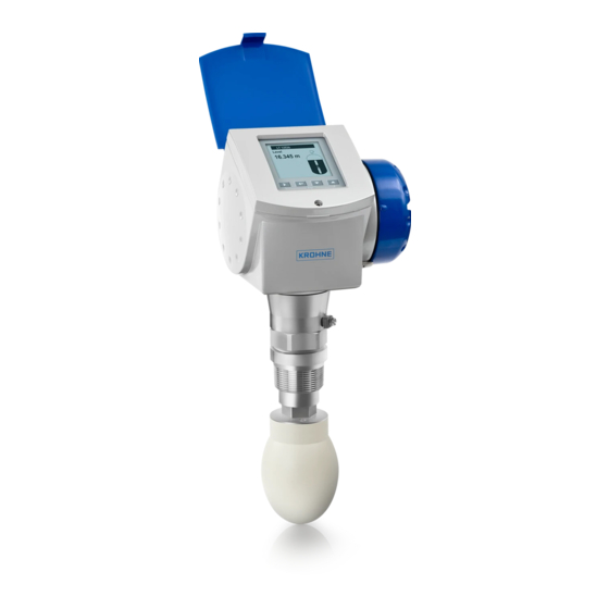
Non-contact radar (fmcw) level meter for distance, level and volume measurement of solids
Hide thumbs
Also See for optiwave 6300 c:
- Handbook (128 pages) ,
- Technical data sheet (40 pages) ,
- Supplementary instructions manual (28 pages)
Table of Contents
Advertisement
Quick Links
Download this manual
See also:
Handbook
Advertisement
Table of Contents

Related Manuals for KROHNE optiwave 6300 c


Summary of Contents for KROHNE optiwave 6300 c
- Page 1 OPTIWAVE 6300 C Handbook Non-contact Radar (FMCW) Level Meter for distance, level and volume measurement of solids © KROHNE 04/2009 - 4000547001 - HB OPTIWAVE 6300 R01 en...
- Page 2 KROHNE Messtechnik GmbH & Co. KG. Subject to change without notice. Copyright 2009 by KROHNE Messtechnik GmbH & Co. KG - Ludwig-Krohne-Straße 5 - 47058 Duisburg www.krohne.com 04/2009 - 4000547001 - HB OPTIWAVE 6300 R01 en...
-
Page 3: Table Of Contents
CONTENTS OPTIWAVE 6300 C 1 Safety instructions 1.1 Intended use ........................6 1.2 Certification ........................6 1.3 Electromagnetic compatibility ..................6 1.4 Radio approvals ........................ 7 1.4.1 European Union (EU)....................... 7 1.4.2 U.S.A............................8 1.5 Safety instructions from the manufacturer ..............8 1.5.1 Copyright and data protection .................... - Page 4 CONTENTS OPTIWAVE 6300 C 4.4 Networks ........................33 4.4.1 General information......................33 4.4.2 Point-to-point connection ..................... 33 4.4.3 Multi-drop networks ......................34 5 Start-up 5.1 Start-up checklist......................35 5.2 Operating concept ......................35 5.3 Digital display screen ..................... 36 5.3.1 Local display screen layout ....................36 5.3.2 Push-button functions ......................
- Page 5 CONTENTS OPTIWAVE 6300 C 7.4.4 Replacement of the terminal module................... 80 7.5 Spare parts availability....................82 7.5.1 List of spare parts ......................... 82 7.5.2 List of accessories ........................ 84 7.6 Availability of services ....................86 7.7 Returning the device to the manufacturer..............86 7.7.1 General information......................
-
Page 6: Safety Instructions
SAFETY INSTRUCTIONS OPTIWAVE 6300 C 1.1 Intended use This radar level transmitter measures distance, level, mass, volume and reflectivity of granulates and powders. It can be installed on silos and bunkers. 1.2 Certification DANGER! For devices used in hazardous areas, additional safety notes apply; please refer to the Ex documentation. -
Page 7: Radio Approvals
SAFETY INSTRUCTIONS OPTIWAVE 6300 C 1.4 Radio approvals 1.4.1 European Union (EU) LEGAL NOTICE! This level transmitter is intended for installation in closed metallic tanks. It meets the requirements of the R & TTE (Radio Equipment and Telecommunications Terminal Equipment) Directive 1999/05/EC for use in the member countries of the EU. -
Page 8: Safety Instructions From The Manufacturer
SAFETY INSTRUCTIONS OPTIWAVE 6300 C 1.4.2 U.S.A. LEGAL NOTICE! This device complies with Part 15 of the FCC Rules. Operation is subject to the following two conditions: 1. This device may not cause harmful interference, and 2. this device must accept any interference received, including interference which may cause un- desired operation. -
Page 9: Disclaimer
SAFETY INSTRUCTIONS OPTIWAVE 6300 C 1.5.2 Disclaimer The manufacturer will not be liable for any damage of any kind by using its product, including, but not limited to direct, indirect, incidental, punitive and consequential damages. This disclaimer does not apply in case the manufacturer has acted on purpose or with gross negligence. -
Page 10: Warnings And Symbols Used
SAFETY INSTRUCTIONS OPTIWAVE 6300 C 1.5.5 Warnings and symbols used Safety warnings are indicated by the following symbols. DANGER! This information refers to the immediate danger when working with electricity. DANGER! This warning refers to the immediate danger of burns caused by heat or hot surfaces. -
Page 11: Device Description
DEVICE DESCRIPTION OPTIWAVE 6300 C 2.1 Scope of delivery INFORMATION! Inspect the cartons carefully for damage or signs of rough handling. Report damage to the carrier and to the local office of the manufacturer. INFORMATION! Check the packing list to check if you received completely all that you ordered. - Page 12 DEVICE DESCRIPTION OPTIWAVE 6300 C Scope of delivery - Drop antenna Figure 2-2: Scope of delivery - Drop antenna 1 Signal converter and antenna in compact version 2 Antenna extensions (option) and o-ring for each antenna extension 3 Quick Start...
-
Page 13: Device Description
DEVICE DESCRIPTION OPTIWAVE 6300 C 2.2 Device description This device is a 24 GHz FMCW-radar level transmitter. It is a non-contact technology and is 2- wire loop-powered. It is designed to measure the distance, level, mass, volume and reflectivity of granulates and powders. -
Page 14: Visual Check
DEVICE DESCRIPTION OPTIWAVE 6300 C 2.3 Visual Check WARNING! If the display screen glass is broken, do not touch. INFORMATION! Inspect the cartons carefully for damage or signs of rough handling. Report damage to the carrier and to the local office of the manufacturer. -
Page 15: Nameplates
DEVICE DESCRIPTION OPTIWAVE 6300 C 2.4 Nameplates INFORMATION! Look at the device nameplate to ensure that the device is delivered according to your order. Check for the correct supply voltage printed on the nameplate. 2.4.1 Non-Ex nameplate Figure 2-4: Non-Ex nameplate 1 Indicator arrow to cable entry / cable entry size. -
Page 16: Installation
INSTALLATION OPTIWAVE 6300 C 3.1 Notes on installation INFORMATION! Inspect the cartons carefully for damage or signs of rough handling. Report damage to the carrier and to the local office of the manufacturer. INFORMATION! Check the packing list to check if you received completely all that you ordered. -
Page 17: Transport
INSTALLATION OPTIWAVE 6300 C 3.3 Transport Figure 3-2: How to lift the device 1 Remove the converter before you lift the device with a hoist. WARNING! Lift the device carefully to prevent damage to the antenna. 3.4 Pre-installation requirements INFORMATION! The following precautions must be taken to make sure it is correctly installed. -
Page 18: How To Prepare The Silo Before You Install The Device
INSTALLATION OPTIWAVE 6300 C 3.5 How to prepare the silo before you install the device CAUTION! To avoid measuring errors and device malfunction, obey these precautions. 3.5.1 Pressure and temperature ranges Figure 3-3: Pressure and temperature ranges 1 Flange temperature FKM/FPM gasket: -40...200°C / -40...390°F;... -
Page 19: Theoretical Data For Nozzle Position
INSTALLATION OPTIWAVE 6300 C 3.5.2 Theoretical data for nozzle position CAUTION! Follow these recommendations to make sure that the device measures correctly. Figure 3-4: Recommended nozzle position for solids 1 Position of the process fitting from the silo wall, r/2 (for DN80 or DN100 Horn antennas, and DN80 or DN150 Drop... - Page 20 INSTALLATION OPTIWAVE 6300 C Figure 3-5: Product inlets 1 The device is in the correct position. 2 The device is too near to the product inlet. Figure 3-6: More than 1 FMCW radar level meter can be operated in a silo More than 1 FMCW radar level meter can be operated in a silo.
-
Page 21: Installation Recommendations For Solids
INSTALLATION OPTIWAVE 6300 C 3.6 Installation recommendations for solids CAUTION! Do not install the device above objects in the silo (ladder, supports etc.). Objects in the silo can cause parasite radar signals. If there are parasite radar signals, the device will not measure correctly. -
Page 22: How To Install The Device On The Silo
INSTALLATION OPTIWAVE 6300 C 3.7 How to install the device on the silo 3.7.1 How to install a device with a flange connection Equipment needed: • Device • Gasket (not supplied) • Nuts and bolts (not supplied) • Wrench (not supplied) - Page 23 INSTALLATION OPTIWAVE 6300 C Figure 3-9: How to attach the device if the antenna is smaller than the process connection Equipment needed (not supplied): • 3 mm Allen wrench WARNING! If you attach the antenna in a closed space, make sure that there is a good airflow in the area.
-
Page 24: How To Install A Device With A Threaded Connection
INSTALLATION OPTIWAVE 6300 C 3.7.2 How to install a device with a threaded connection Equipment needed: • Device • Gasket for G 1½ connection (not supplied) • 50 mm / 2¨ wrench (not supplied) Requirements for threaded connections Figure 3-10: Threaded connection If the process connection is larger than the antenna •... - Page 25 INSTALLATION OPTIWAVE 6300 C Figure 3-11: How to attach the device if the antenna is smaller than the process connection Equipment needed (not supplied): • 3 mm Allen wrench WARNING! If you attach the antenna in a closed space, make sure that there is a good airflow in the area.
-
Page 26: How To Attach Antenna Extensions
INSTALLATION OPTIWAVE 6300 C 3.7.3 How to attach antenna extensions Horn antenna - antenna extensions Figure 3-12: Horn antenna - how to attach antenna extensions • Attach the antenna extensions 1 below the flange. • Attach the antenna 2. • Make sure the antenna extensions are fully engaged. -
Page 27: How To Turn Or Remove The Signal Converter
INSTALLATION OPTIWAVE 6300 C • Remove the o-rings from the plastic sachet supplied with the device. Put an o-ring 4 into the groove at the top of each antenna extension. • Attach the antenna extensions 1 below the flange. • Attach the antenna 2. -
Page 28: How To Attach The Weather Protection To The Device
INSTALLATION OPTIWAVE 6300 C How to remove the signal converter • Loosen the housing locking screw 1 with a 5 mm Allen wrench. • Remove the housing. • Tighten the housing locking screw 1. How to attach the signal converter •... -
Page 29: How To Open The Weather Protection
INSTALLATION OPTIWAVE 6300 C 3.7.6 How to open the weather protection Equipment needed: • Weather protection. • Large slotted tip screwdriver (not supplied). Figure 3-16: How to open the weather protection 1 Weather protection in its closed position 2 Weather protection in its open position. Minimum clearance in front of the device: 300 mm / 12¨. -
Page 30: Electrical Connections
ELECTRICAL CONNECTIONS OPTIWAVE 6300 C 4.1 Safety instructions DANGER! All work on the electrical connections may only be carried out with the power disconnected. Take note of the voltage data on the nameplate! DANGER! Observe the national regulations for electrical installations! DANGER! For devices used in hazardous areas, additional safety notes apply;... -
Page 31: Non-Ex
ELECTRICAL CONNECTIONS OPTIWAVE 6300 C Procedure: • Remove the housing terminal compartment cover 1. • Connect the wires to the device. Obey the national electrical codes. • Make sure that the polarity of the wires is correct. • Attach the ground to 4 or 7. Both terminals are technically equivalent. -
Page 32: Protection Category
ELECTRICAL CONNECTIONS OPTIWAVE 6300 C 4.3 Protection category INFORMATION! The device fulfills all requirements per protection class IP 66/67 (equivalent to NEMA 6-6X). DANGER! Make sure the cable gland is watertight. Figure 4-3: How to make the installation agree with protection category IP 67 •... -
Page 33: Networks
ELECTRICAL CONNECTIONS OPTIWAVE 6300 C 4.4 Networks 4.4.1 General information ® ® The device uses the HART communication protocol. This protocol agrees with the HART Communication Foundation standard. The device can be connected point-to-point. It can also operate in a multi-drop network of up to 15 devices. -
Page 34: Multi-Drop Networks
ELECTRICAL CONNECTIONS OPTIWAVE 6300 C 4.4.3 Multi-drop networks Figure 4-5: Multi-drop network (non-Ex) 1 Address of the device (n+1 for multidrop networks) 2 Address of the device (1 for multidrop networks) ® 3 4 mA + HART ® 4 Resistor for HART... -
Page 35: Start-Up
START-UP OPTIWAVE 6300 C 5.1 Start-up checklist Check these points before you energize the device: • Are all the wetted components (antenna, flange and gaskets) resistant to the product in the silo? • Does the information on the signal converter nameplate agree with the operating data? •... -
Page 36: Digital Display Screen
START-UP OPTIWAVE 6300 C 5.3 Digital display screen 5.3.1 Local display screen layout Figure 5-1: Local display screen layout 1 Error icon 2 Tag number or menu name 3 Selected menu item (grey text cannot be selected) : scroll up/scroll down 5 Push buttons (refer to the table below) 5.3.2 Push-button functions... -
Page 37: How To Start The Device
START-UP OPTIWAVE 6300 C 5.3.4 How to start the device • Connect the converter to the power supply. • Energize the converter. After 30 seconds the screen will display "booting up", "starting up" and then the default screen will appear. -
Page 38: Remote Communication With The Ams™ Device Manager
START-UP OPTIWAVE 6300 C Figure 5-2: Screen from the PACTware™ user interface 1 DTM menu 2 Basic measurement information: level, current output and device status 3 Information for device identification 4 Configuration summary 5.5 Remote communication with the AMS™ Device Manager The AMS™... -
Page 39: Operation
OPERATION OPTIWAVE 6300 C 6.1 User modes There are 3 modes of operation: • Operator. • Supervisor. • Service. 6.2 Operator mode The operator can choose what information to display. This section shows you: • What each button does in operator mode. - Page 40 OPERATION OPTIWAVE 6300 C Screens in operator mode Text and image Go to % current output Go to Text screen Go to screen screen Level > Level > Level > (Text and image) Distance > Distance > Distance > (Text...
-
Page 41: Supervisor Mode
OPERATION OPTIWAVE 6300 C 6.3 Supervisor mode 6.3.1 General notes Configure your device in supervisor mode. You can: • Use the quick setup menus to configure your device quickly. For more data about quick setup Function description menus, refer to on page 46 (Table A. -
Page 42: Menu Overview
OPERATION OPTIWAVE 6300 C 6.3.3 Menu overview A quick setup setup mode quick link 1 (default: error records) quick link 2 (default: contrast) quick link 3 (default: language) quick link 4 (default: length unit) quick link 5 (default: display) B test... -
Page 43: Push-Button Functions
OPERATION OPTIWAVE 6300 C 6.3.4 Push-button functions Menu navigation Figure 6-1: Menu navigation 1 Menu selection bar 2 Header bar 3 Menu list 4 Menu item that is not available (in grey text) This is what you see when you are in the list of menus in supervisor mode. The functions of the... - Page 44 OPERATION OPTIWAVE 6300 C Lists of parameters in menu items Figure 6-2: Lists of parameters in menu items 1 Parameter selection bar 2 Menu name 3 Parameter used at this time This is what you see when you choose a menu item that has a list of parameters. The functions of...
- Page 45 OPERATION OPTIWAVE 6300 C Values in menu items Figure 6-3: Values in menu items 1 Maximum value 2 Minimum value 3 Cursor on the digit to be changed 4 Menu name 5 Illustration of menu item 6 Error message This is what you see when you choose a menu item that has a value. The functions of the push-...
-
Page 46: Function Description
OPERATION OPTIWAVE 6300 C If you press the push-buttons for 1 second, you can use these hotkey functions: Hotkey functions in supervisor mode Push button Description Function Right Create a quick link Enter Down Screen displays information in English Esc (Escape) - Page 47 OPERATION OPTIWAVE 6300 C Menu Step Function Function description Selection list Default application type The conditions in slant surface; flat slant which the device is surface; big slope surface used. If the surface of the product is flat, select "flat surface". If...
- Page 48 OPERATION OPTIWAVE 6300 C Menu Step Function Function description Selection list Default do you want to save If you save this data, save, cancel save the spectrum? the device will use it when it measures the silo contents. A.1.4 conversion...
- Page 49 OPERATION OPTIWAVE 6300 C Menu Step Function Function description Selection list Default free unit yes, no customer length A non-standard length LEN_FREE unit unit for the conversion table. This is defined by the supervisor. customer length The conversion factor min-max: 1…99999...
- Page 50 OPERATION OPTIWAVE 6300 C Menu Step Function Function description Selection list Default output 2: 20 mA This assigns a min.-max: 0…90 m / depends setting measurement value to 0…295.29 ft on the 20 mA. output function output 2: output This sets the effective 3.8…20.5 mA...
- Page 51 OPERATION OPTIWAVE 6300 C Menu Function Function description Selection list Default B.1.2 set output 1 This sets analogue output 1 to a test 3.6, 4, 6, 8, 10, 12, 14, 4 mA value [mA] selected from a list. 16, 18, 20 or 22 mA...
- Page 52 OPERATION OPTIWAVE 6300 C C. Advanced setup Menu Function Function description Selection list Default advanced setup Select single menu items to fine-tune the device. installation setup C.1.1 installation The installation on the silo for metal / concrete silo, plastic metal / type the device.
- Page 53 OPERATION OPTIWAVE 6300 C Menu Function Function description Selection list Default C.1.11 tank bottom Offset relating to a reference min-max: 0 m / 0 ft offset location (level). The device -tank height...3000 m / reference point for this -tank height...9843 ft...
- Page 54 OPERATION OPTIWAVE 6300 C Menu Function Function description Selection list Default C.1.17 empty This function starts and stops on; off spectrum interference signal filter. on/off Interference signals are the result of fixed and moving obstacles inside the silo. If you must use do a spectrum analysis, record an empty spectrum first.
- Page 55 OPERATION OPTIWAVE 6300 C Menu Function Function description Selection list Default error handling The time after which the min.-max: 0…900 seconds 10 seconds delay device shows there is a measurement error. C.3.6 HART address min.-max: 0…15 ® Any HART address greater ®...
- Page 56 OPERATION OPTIWAVE 6300 C Menu Function Function description Selection list Default contrast menu The contrast control for the min.-max: level 1…9 level 5 display screen. You can select a shade of grey between light grey (level 1) and black (level C.5.1.4...
-
Page 57: Further Information On Device Configuration
OPERATION OPTIWAVE 6300 C Data dependencies for the 20 mA settings of outputs 1 and 2 Output function Minimum value Maximum value Default Level >4 mA setting for level Tank height + TBO + RO Tank height + TBO - BD Volume >4 mA setting for volume... -
Page 58: Protection Of The Device Settings
OPERATION OPTIWAVE 6300 C How to create a Quick Link • Go to Supervisor Menu > Advanced Setup. • Select a menu item with the push buttons. • Press the > push button for one second. The device saves this menu item as a Quick Link. Example text: Mass Unit has been... -
Page 59: Network Configuration
OPERATION OPTIWAVE 6300 C 6.4.3 Network configuration INFORMATION! For more data, refer to Networks on page 33 ® ® The device uses HART communication to send information to HART -compatible equipment. It can operate in either point-to-point or multidrop mode. The device will communicate in ®... -
Page 60: Linearisation
OPERATION OPTIWAVE 6300 C 6.4.4 Linearisation You can use the linearisation table given in function to make sure that readings are consistently accurate. • Go to Supervisor > Advanced setup > Installation setup > Linearisation table. • Type in the number of reference points (up to 50 points). Press ^. -
Page 61: Level Measurement
OPERATION OPTIWAVE 6300 C Figure 6-5: Distance measurement 1 Tank height (C.1.2) 2 Reference offset (C.1.10) 3 Blocking distance (C.1.9) 4 4 mA setting (C.3.2 or C.4.2) 5 20 mA setting (C.3.3 or C.4.3) 6 Maximum effective measuring range 7 Non-measurement zone... - Page 62 OPERATION OPTIWAVE 6300 C Figure 6-6: Level measurement 1 Tank bottom offset (C.1.11) 2 Tank height (C.1.2) 3 Blocking distance (C.1.9) 4 Maximum effective measuring range 5 20 mA setting (C.3.3 or C.4.3) 6 4 mA setting (C.3.2 or C.4.2)
-
Page 63: How To Configure The Device To Measure Volume Or Mass
OPERATION OPTIWAVE 6300 C 6.4.7 How to configure the device to measure volume or mass The device can be configured to measure volume or mass. The procedure for doing this is given in the device's Quick Setup menu. How to create a volume or mass table. -
Page 64: How To Use The Empty Spectrum Function To Filter Parasite Signals
OPERATION OPTIWAVE 6300 C 6.4.8 How to use the empty spectrum function to filter parasite signals If the device measures level in a silo that contains obstructions (ladder, supports etc.), these objects can cause radar signal interference. You can use the empty spectrum function in the device's Quick Setup menu to filter radar signal interference. -
Page 65: How To Measure Correctly In Silos With Curved Or Conical Bottoms
OPERATION OPTIWAVE 6300 C If you select Yes, the device will use the empty spectrum scan results to filter out radar signal interference. INFORMATION! For more data on empty spectrum scans, refer to Function description on page 46 - table A. -
Page 66: Service Mode
OPERATION OPTIWAVE 6300 C Figure 6-9: Signal screen and the silo bottom reflection 1 Tank bottom offset (menu item C.1.11) 2 Tank height (menu item C.1.2) 3 Signal amplitude (in dB) 4 True position of the silo bottom 5 Offset position of the silo bottom... -
Page 67: Errors
OPERATION OPTIWAVE 6300 C 6.6 Errors 6.6.1 General information Indication of errors When the device senses an error condition, it displays an error symbol in the top left corner of the display screen. Figure 6-10: Indication of errors 1 Error/ warning symbol Enter the supervisor mode to either: •... - Page 68 OPERATION OPTIWAVE 6300 C Figure 6-11: Measurement quality in supervisor mode 1 Type of error. 2 Error "active" How to find the error records • Enter supervisor mode. • Go to Test > Information > Error records. • Use to scroll the error list. There are 5 error messages per page.
- Page 69 OPERATION OPTIWAVE 6300 C How to get more data about the error (error records function) • Select an error log and press ^ to read the help text. Typical data is given in the illustration that follows. Error handling • For solutions to the problem, refer to on page 70.
-
Page 70: Error Handling
OPERATION OPTIWAVE 6300 C 6.6.2 Error handling Types of error message Type of error Error Description code Error If an error message is displayed in the error record (menu item B.2.6), the measured value is not correct. The output current goes to the value set in menu items C.3.5 Error Handling (Ouput 1) and C.4.5 Error Handling (Output 2). - Page 71 OPERATION OPTIWAVE 6300 C Self-test manager Self Test has failed The device's self-test failed. Energize the device when the This can occur if the ambient ambient temperature is temperature is not between - between -40...+80°C / - 40...+80°C / -40...175°F.
- Page 72 OPERATION OPTIWAVE 6300 C Peak and spectrum Spectrum quality is bad The quality of the spectrum is Check the device, silo and the poor. If this message is process. Reconfigure the temporarily shown, this will device and record a new not affect the performance of empty spectrum.
-
Page 73: Service
SERVICE OPTIWAVE 6300 C 7.1 Periodic maintenance No maintenance is necessary. 7.2 How to clean the top surface of the device WARNING! Do not let more than 5 mm / 0.2 of dust collect on the top surface of the device. This is a possible ¨... -
Page 74: How To Clean Horn Antennas Under Process Conditions
SERVICE OPTIWAVE 6300 C 7.3 How to clean horn antennas under process conditions If it is possible that there will be build-up, a purging option is available for horn antennas. WARNING! Purge the antenna with a dry gas that is applicable to the process. -
Page 75: How To Replace Device Components
SERVICE OPTIWAVE 6300 C 7.4 How to replace device components 7.4.1 Service warranty Maintenance is not necessary for most applications. Servicing by the customer is limited by warranty to How to • The removal and installation of the signal converter housing. For more data, refer to turn or remove the signal converter on page 27. -
Page 76: Replacement Of The Display Cover
SERVICE OPTIWAVE 6300 C 7.4.2 Replacement of the display cover Figure 7-1: Removal of the device display cover Equipment needed (not supplied): • Slotted tip screwdriver. • 3 mm Allen wrench (for steps 2 and 4). www.krohne.com 04/2009 - 4000547001 - HB OPTIWAVE 6300 R01 en... - Page 77 SERVICE OPTIWAVE 6300 C WARNING! Disconnect the power supply How to remove the display 1 Remove the 2 pins on the blue sun cover with a slotted tip screwdriver. Remove the sun cover. 2 Loosen the screw on the display screen cover. Open the display.
-
Page 78: Replacement Of The Back End And Microwave Unit
SERVICE OPTIWAVE 6300 C 7.4.3 Replacement of the back end and microwave unit Figure 7-2: Removal of the back end and microwave unit Equipment needed (not supplied): • 3 mm Allen wrench (for steps 1 and 4). www.krohne.com 04/2009 - 4000547001 - HB OPTIWAVE 6300 R01 en... - Page 79 SERVICE OPTIWAVE 6300 C How to remove the back end and microwave unit 1 Loosen the screw on the display. Open the display. 2 Disconnect the power supply connector from the electronics block. 3 Disconnect the display ribbon cable from the back end electronics block.
-
Page 80: Replacement Of The Terminal Module
SERVICE OPTIWAVE 6300 C 7.4.4 Replacement of the terminal module WARNING! Disconnect the power supply. Figure 7-3: Removal of the terminal module Equipment needed (not supplied): • 3 mm Allen wrench (for step 1). • TORX T10 wrench (for step 4). - Page 81 SERVICE OPTIWAVE 6300 C How to remove the terminal module 1 Loosen the cover stop screw on the terminal compartment cover. 2 Remove the terminal compartment cover. 3 Remove the plastic terminal cover. 4 Loosen the screw for the earth terminal connection.
-
Page 82: Spare Parts Availability
SERVICE OPTIWAVE 6300 C 7.5 Spare parts availability The manufacturer adheres to the basic principle that operational spare parts for each device or each important accessory part will be kept available for a period of 10 (ten) years after delivery of the last production run for that device. - Page 83 SERVICE OPTIWAVE 6300 C Part numbers for spare parts Item number Description Quantity Part reference Combined backend and high-frequency modules F2139580100 Screws for the combined back end and HF modules F3177360000 HMI cover and cable XF6340000000050300 Terminal module with 1 output (non-Ex)
-
Page 84: List Of Accessories
SERVICE OPTIWAVE 6300 C 7.5.2 List of accessories Figure 7-5: Accessories www.krohne.com 04/2009 - 4000547001 - HB OPTIWAVE 6300 R01 en... - Page 85 SERVICE OPTIWAVE 6300 C Part numbers for accessories Item number Description Quantity Part reference Plastic sun cover F3179980000 Pins for the plastic sun cover F3179990000 Stainless steel weather protection F2096340000 Blind cover (with a gasket and screws) F3177240100 Gasket for the blind cover...
-
Page 86: Availability Of Services
SERVICE OPTIWAVE 6300 C 7.6 Availability of services The manufacturer offers a range of services to support the customer after expiration of the warranty. These include repair, technical support and training. INFORMATION! For more precise information, please contact your local representative. -
Page 87: Form (For Copying) To Accompany A Returned Device
SERVICE OPTIWAVE 6300 C 7.7.2 Form (for copying) to accompany a returned device Company: Address: Department: Name: Tel. no.: Fax no.: Manufacturer's order no. or serial no.: The device has been operated with the following medium: This medium is: water-hazardous... -
Page 88: Technical Data
TECHNICAL DATA OPTIWAVE 6300 C 8.1 Measuring principle A radar signal is emitted via an antenna, reflected on the product surface and received after a time t. The radar principle used is FMCW (Frequency Modulated Continuous Wave). The FMCW-radar transmits a high frequency signal whose frequency increases linearly during the measurement phase (called the frequency sweep). -
Page 89: Technical Data
TECHNICAL DATA OPTIWAVE 6300 C 8.2 Technical data INFORMATION! • The following data is provided for general applications. If you require data that is more relevant to your specific application, please contact us or your local representative. Additional information (certificates, special tools, software,...) and complete product •... - Page 90 TECHNICAL DATA OPTIWAVE 6300 C Reference conditions acc. to EN 60770 Temperature +20°C ±5°C / +70°F ±10°F Pressure 1013 mbar abs. ±20 mbar / 14.69 psig ±0.29 psig Relative air humidity 60% ±15% Target metal plate in an anechoic chamber...
- Page 91 TECHNICAL DATA OPTIWAVE 6300 C Materials Housing Standard: Aluminium Option: Stainless steel (1.4404 / 316L) Wetted parts, including antenna Standard for Horn antenna: Stainless steel (1.4404 / 316L) ® Option for Horn antenna: Hastelloy C-22 (2.4602) Standard for Drop antenna: PTFE; PP - a PP or PTFE flange plate option is also...
- Page 92 TECHNICAL DATA OPTIWAVE 6300 C Approvals and certification This device fufills the statutory requirements of the EC directives. The manufacturer certifies successful testing of the product by applying the CE mark. Explosion protection ATEX ATEX II G 1, 1/2, 2 Ex ia IIC T6...T3;...
-
Page 93: Antenna Selection
TECHNICAL DATA OPTIWAVE 6300 C 8.3 Antenna selection This graph shows which antenna to select for the application based on: • D, the measuring range and • ε , is the dielectric constant of the product being measured Figure 8-2: Selection of antenna for solid applications (graph of distance in m against ε... -
Page 94: Dimensions And Weights
TECHNICAL DATA OPTIWAVE 6300 C 8.4 Dimensions and weights Housing Figure 8-4: Housing dimensions 1 Housing front view 2 Housing side view Dimensions and weights in mm and kg Dimensions [mm] Weights [kg] Housing 158.5 1 if fitted with standard cable glands... - Page 95 TECHNICAL DATA OPTIWAVE 6300 C Weather protection Figure 8-5: Dimensions of the weather protection option 1 Weather protection, back view 2 Weather protection, left side view Dimensions and weights in mm and kg Dimensions [mm] Weights [kg] Weather 231.5 protection...
- Page 96 TECHNICAL DATA OPTIWAVE 6300 C DN80/3¨ horn antenna versions Figure 8-6: DN80/3¨ horn antenna versions 1 DN80/3¨ horn antenna with G1½ or 1½NPT thread connection 2 DN80/3¨ horn antenna with flange connection Dimensions and weights in mm and kg Dimensions [mm]...
- Page 97 TECHNICAL DATA OPTIWAVE 6300 C DN100/4¨ horn antenna versions Figure 8-7: DN100/4¨ horn antenna versions 1 DN100/4¨ horn antenna with G1½ or 1½NPT thread connection 2 DN100/4¨ horn antenna with flange connection Dimensions and weights in mm and kg Dimensions [mm]...
- Page 98 TECHNICAL DATA OPTIWAVE 6300 C DN80/3¨ Drop antenna versions Figure 8-8: DN80/3¨ Drop antenna versions 1 DN80/3¨ Drop antenna with G1½ or 1½NPT thread connection 2 DN80/3¨ Drop antenna with flange connection 3 DN80/3¨ Drop antenna with slanted flange connection (PP material option only) 4 DN80/3¨...
- Page 99 TECHNICAL DATA OPTIWAVE 6300 C DN150/6¨ Drop antenna versions (PP material option only) Figure 8-9: DN150/6¨ Drop antenna versions (PP material option only) 1 DN150/6¨ Drop antenna with flange connection 2 DN150/6¨ Drop antenna with thread connection 3 DN150/6¨ Drop antenna with slanted flange connection 4 DN150/6¨...
-
Page 100: Appendix
9.1 Order form You can help us to assist you as quickly as possible by giving us a few items of information. Then just fax them to us. Your personal KROHNE consultant will contact you within 24 hours. 9.1.1 Device data... -
Page 101: Glossary
APPENDIX OPTIWAVE 6300 C 9.2 Glossary Dead zone Non-measurement zone. Dielectric constant An electrical property of the product to be measured used in Radar measurement. Also known as εr, DK and relative permittivity. Defines the strength of the wave reflected back to the device's signal converter. - Page 102 APPENDIX OPTIWAVE 6300 C Mass Total mass of silo contents. Operators Users who can choose how to display measurements. They cannot configure the device in supervisor mode. PACTware™ Software that operates and configures field devices from a remote workstation. It is not necessary to use fieldbus software or programs developed by the manufacturer.
- Page 103 APPENDIX OPTIWAVE 6300 C Figure 9-1: Measurement definitions: distance 1 Distance 2 Dead zone 3 Flange facing 4 Gas (Air) 5 Tank height 6 Ullage volume or mass Figure 9-2: Measurement definitions: level 1 Level 2 Volume or mass 04/2009 - 4000547001 - HB OPTIWAVE 6300 R01 en...
- Page 104 Measuring systems for sea-going tankers Head Office KROHNE Messtechnik GmbH & Co. KG Ludwig-Krohne-Str. 5 D-47058 Duisburg (Germany) Tel.:+49 (0)203 301 0 Fax:+49 (0)203 301 10389 info@krohne.de The current list of all KROHNE contacts and addresses can be found at: www.krohne.com...
Need help?
Do you have a question about the optiwave 6300 c and is the answer not in the manual?
Questions and answers