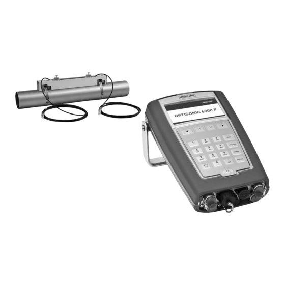
KROHNE OPTISONIC 6300 P Handbook
Portable ultrasonic clamp-on flowmeter
Hide thumbs
Also See for OPTISONIC 6300 P:
- Handbook (76 pages) ,
- Quick start (4 pages) ,
- Short manual (2 pages)
Table of Contents
Advertisement
Quick Links
Advertisement
Table of Contents

Related Manuals for KROHNE OPTISONIC 6300 P


Summary of Contents for KROHNE OPTISONIC 6300 P
- Page 1 OPTISONIC 6300 P OPTISONIC 6300 P OPTISONIC 6300 P OPTISONIC 6300 P Handbook Handbook Handbook Handbook Portable ultrasonic clamp-on flowmeter Electronic Revision: ER 1.1.2_ (SW.REV 01.01.01_) © KROHNE 03/2013 - 4000972603 - MA OPTISONIC 6300 P R03 en...
- Page 2 All rights reserved. It is prohibited to reproduce this documentation, or any part thereof, without the prior written authorisation of KROHNE Messtechnik GmbH. Subject to change without notice. Copyright 2013 by KROHNE Messtechnik GmbH - Ludwig-Krohne-Str. 5 - 47058 Duisburg (Germany) www.krohne.com 03/2013 - 4000972603 - MA OPTISONIC 6300 P R03 en...
-
Page 3: Table Of Contents
4.2 Mechanical installation ....................36 4.3 Program the converter....................38 4.3.1 Program the I/O input ......................38 4.3.2 Program the process input....................39 4.3.3 Program the counters......................40 4.4 Start measurement ......................41 03/2013 - 4000972603 - MA OPTISONIC 6300 P R03 en www.krohne.com... - Page 4 8.2 Technical data......................... 76 8.3 Dimensions and weights ....................82 8.3.1 Clamp-on sensor ........................82 8.3.2 Converter..........................83 8.3.3 I/O box ........................... 84 8.3.4 Trunk on wheels........................85 9 Notes www.krohne.com 03/2013 - 4000972603 - MA OPTISONIC 6300 P R03 en...
-
Page 5: Safety Instructions
The manufacturer is not liable for any damage resulting from improper use or use for other than the intended purpose. The OPTISONIC 6300 P OPTISONIC 6300 P portable clamp-on flow meter is designed for measurement of liquid OPTISONIC 6300 P OPTISONIC 6300 P flows in full pipes, datalogging and transfer of logged results to the PC. -
Page 6: Safety Instructions From The Manufacturer
The manufacturer reserves the right to alter the content of its documents, including this disclaimer in any way, at any time, for any reason, without prior notification, and will not be liable in any way for possible consequences of such changes. www.krohne.com 03/2013 - 4000972603 - MA OPTISONIC 6300 P R03 en... -
Page 7: Product Liability And Warranty
This document is provided to help you establish operating conditions, which will permit safe and efficient use of this device. Special considerations and precautions are also described in the document, which appear in the form of underneath icons. 03/2013 - 4000972603 - MA OPTISONIC 6300 P R03 en www.krohne.com... -
Page 8: Warnings And Symbols Used
This symbol designates all instructions for actions to be carried out by the operator in the specified sequence. RESULT RESULT RESULT RESULT This symbol refers to all important consequences of the previous actions. www.krohne.com 03/2013 - 4000972603 - MA OPTISONIC 6300 P R03 en... -
Page 9: Device Description
9 UFC 300 P Signal converter INFORMATION! Delivered content can be different, dependent on the ordered version. A checklist is included with the product, check if all items on this checklist are delivered. 03/2013 - 4000972603 - MA OPTISONIC 6300 P R03 en www.krohne.com... -
Page 10: Nameplates
1 Name and address of the manufacturer 2 Device type 3 Serial number 4 Manufacturing year 5 Protection class and temperature data 6 Treat device as electronic garbage according WEEE rules. www.krohne.com 03/2013 - 4000972603 - MA OPTISONIC 6300 P R03 en... - Page 11 DEVICE DESCRIPTION OPTISONIC 6300 P Figure 2-4: Nameplate I/O box, standard version Figure 2-5: Nameplate I/O box with 2 temperature transmitters included. 03/2013 - 4000972603 - MA OPTISONIC 6300 P R03 en www.krohne.com...
-
Page 12: Installation For Flow Measurement
Specific for converters: WARNING! Be careful moving the handle of the converter, as your fingers may get stuck between the handle and the housing of the converter. This may cause injury. www.krohne.com 03/2013 - 4000972603 - MA OPTISONIC 6300 P R03 en... -
Page 13: Step 1: Find Location And Determine Data
Follow the given installation recommendations. Figure 3-1: Inlet, outlet and recommended mounting area 1 Min. 10 DN 2 Min. 5 DN 3 Recommended installation location (120°) 03/2013 - 4000972603 - MA OPTISONIC 6300 P R03 en www.krohne.com... - Page 14 CAUTION! Make sure that the pipe is fully filled at all times. INFORMATION! Both ascending and descending flow directions are measurable. Figure 3-3: Mounting on vertical pipelines is possible www.krohne.com 03/2013 - 4000972603 - MA OPTISONIC 6300 P R03 en...
- Page 15 Position of control valve Always install control valves downstream of the flowmeter in order to avoid cavitation or distortion of the flow profile. Figure 3-6: Position of control valve 03/2013 - 4000972603 - MA OPTISONIC 6300 P R03 en www.krohne.com...
- Page 16 • Find out what the material of the pipe is. • If the pipe has a liner, find out the liner material and the thickness of the liner. www.krohne.com 03/2013 - 4000972603 - MA OPTISONIC 6300 P R03 en...
-
Page 17: Step 2: Initialise The Ufc 300 P Converter
5 On / off button • Turn on the converter by pressing the on / off button for one second. Wait until the menu appears, this will take approximately 30 seconds. 03/2013 - 4000972603 - MA OPTISONIC 6300 P R03 en www.krohne.com... - Page 18 When editing, only the Back and Forward buttons are functional: Back Delete previous character or leave item unchanged when at position one Forward Move cursor right, accept item when at last position www.krohne.com 03/2013 - 4000972603 - MA OPTISONIC 6300 P R03 en...
- Page 19 1 pipe / 1 path 1 pipe / 1 path 1 pipe / 2 path 2 pipes 13-04-2010 14:11:09 13 MB free See the next figure for an explanation of the options: 03/2013 - 4000972603 - MA OPTISONIC 6300 P R03 en www.krohne.com...
- Page 20 Select whether there is a liner or not Liner thickness Fill in the liner thickness The liner thickness will only be shown if a liner material is chosen. Choose next www.krohne.com 03/2013 - 4000972603 - MA OPTISONIC 6300 P R03 en...
- Page 21 Select the value that is on the label on the transducer cable. Note: A maximum of three transducer sets can be programmed in the converter, called Ta, Tb or Tc. 03/2013 - 4000972603 - MA OPTISONIC 6300 P R03 en www.krohne.com...
- Page 22 Normally, install the sensors as advised. If the quality of the pipe walls is poor and / or in case of scaling inside the pipes, try to decrease the amount of traverses or (if possible) use a medium sensor instead of a small sensor. www.krohne.com 03/2013 - 4000972603 - MA OPTISONIC 6300 P R03 en...
-
Page 23: Step 3: Mount The Sensor Rails
Installation with metal straps (DN15...250) Put the metal straps around the pipe. Put the sensor rail(s) on the pipe including the transducers with fixed cables. 03/2013 - 4000972603 - MA OPTISONIC 6300 P R03 en www.krohne.com... - Page 24 3 Pull the straps around the pipe. 4 Insert the straps in the upper opening. 5 Pull the straps tight. 6 Use an allan key nr 5 (or a big screwdriver) to fixate the rails. www.krohne.com 03/2013 - 4000972603 - MA OPTISONIC 6300 P R03 en...
- Page 25 2 Insert the textile strap as indicated. 3 Release lever. 4 Pull strap tight. 5 Use an allan key nr 5 (or a big screwdriver) to fixate the rails. 03/2013 - 4000972603 - MA OPTISONIC 6300 P R03 en www.krohne.com...
-
Page 26: Or 4 Traverses With 1 Rail
• Unlock the transducer by turning the locking knob 2 counter clockwise. • Slide the transducer 1 to the new position 3. • Lock the transducer by turning the locking knob 2 clockwise. www.krohne.com 03/2013 - 4000972603 - MA OPTISONIC 6300 P R03 en... -
Page 27: Traverses With 2 Rails
Put the second transducer at position Z = advised distance 1 + X - distance 2 - 415 mm / 16.3". 03/2013 - 4000972603 - MA OPTISONIC 6300 P R03 en www.krohne.com... -
Page 28: Traverse With 2 Rails (Dn400
Figure 3-13: Mounting second rail in Z mode (1 traverse) using a reference point 1 Measure the distance between the transducer of the UP rail and the reference point. 2 Add the advised distance to determine the position of the second transducer. www.krohne.com 03/2013 - 4000972603 - MA OPTISONIC 6300 P R03 en... -
Page 29: Apply Coupling Grease
Push the buttons of the fixing units to unlock and tilt the rail. Then put some coupling grease on the transducers and put the rail back by clicking. Figure 3-15: Greasing transducers 03/2013 - 4000972603 - MA OPTISONIC 6300 P R03 en www.krohne.com... -
Page 30: Connect The Sensor Cable
High signal 50...75% Fairly high signal 10...50% Low signal < 10% Bad or no signal Check settings in menu, change transducer distance until there is at least a low signal. www.krohne.com 03/2013 - 4000972603 - MA OPTISONIC 6300 P R03 en... -
Page 31: Step 4: Optimization Loop
• The optimization loop will give a new advise on the transducer distance. Slide the transducers to the new position. Repeat this loop until the advised distance does not change more than 1% or 1 mm. 03/2013 - 4000972603 - MA OPTISONIC 6300 P R03 en www.krohne.com... -
Page 32: Step 5: Start Flow Measurement
3.6 Step 5: start flow measurement Press " " on the converter. The converter checks the received signal and initiates the flow measurement mode. The display will show the actual flow now. www.krohne.com 03/2013 - 4000972603 - MA OPTISONIC 6300 P R03 en... -
Page 33: Error Messages
C5.3.7 active settings error during CRC check (Cyclic load settings; factory setting, back Redundancy Check) of the active up 1 or back up 2 settings 03/2013 - 4000972603 - MA OPTISONIC 6300 P R03 en www.krohne.com... - Page 34 DSP and error microprocessor software www.krohne.com 03/2013 - 4000972603 - MA OPTISONIC 6300 P R03 en...
-
Page 35: Installation For Energy Measurement
Optionally, clamp-on PT 100 temperature sensors can be delivered, with a temperature range of 0...120°C / 32...248°F, including two meter cable and suitable for pipes up to DN300. 03/2013 - 4000972603 - MA OPTISONIC 6300 P R03 en www.krohne.com... -
Page 36: Mechanical Installation
If the temperature sensors on the pipe have temperature transmitters 4...20 mA it is possible to make use of the standard I/O box. • Connect the PT 100 elements to the I/O box according to the sticker on the I/O box. www.krohne.com 03/2013 - 4000972603 - MA OPTISONIC 6300 P R03 en... - Page 37 Figure 4-4: Basic I/O box for 4...20 mA temperature transmitters • Plug the connector 2 of the I/O box 3 in the connector 1 of the converter, as shown in the figure below. 03/2013 - 4000972603 - MA OPTISONIC 6300 P R03 en www.krohne.com...
-
Page 38: Program The Converter
Simulation 13-04-2010 14:11:09 13 MB free If the recommended KROHNE energy set is used, the standard settings are correct. The temperature range is 4 mA = 0°C / 32°F and 20 mA = 120°C / 248°F: INFORMATION! On the converter, you must scroll down in the menu to see all settings. -
Page 39: Program The Process Input
In case the function is "Heating", the temperature at the "supply" side is the highest. In case the function is "Cooling", the temperature at the "supply" side is the lowest. 03/2013 - 4000972603 - MA OPTISONIC 6300 P R03 en www.krohne.com... -
Page 40: Program The Counters
• Select "+ counter" for only counting positive energy flows. • Select "- counter" for only counting negative energy flows. • At the "Measurement" option, select "Power". The energy value counter unit is kJ. www.krohne.com 03/2013 - 4000972603 - MA OPTISONIC 6300 P R03 en... -
Page 41: Start Measurement
(2000 pounds or 907 kg) of ice. kilo calorie per second Amount of heat required to 4187 increase 1 kg of water with 1 degree Celsius. Therm Equal to 100000 BTU 105506000 03/2013 - 4000972603 - MA OPTISONIC 6300 P R03 en www.krohne.com... -
Page 42: Electrical Connections
Check for the correct supply voltage printed on the nameplate. 5.2 Location of connectors at the converter All connectors are located at the bottom side of the converter. DISPLAY DC in LOGGER PQRS WXYZ MENU www.krohne.com 03/2013 - 4000972603 - MA OPTISONIC 6300 P R03 en... -
Page 43: Power Supply
Find the calibration numbers that are noted on the labels on the cable of each transducer. Make sure that both transducers have the same calibration number as shown by the converter. INFORMATION! The signal cables are prefixed to the transducers in the factory. 03/2013 - 4000972603 - MA OPTISONIC 6300 P R03 en www.krohne.com... -
Page 44: Usb Connector
1. Read / write data to a memorystick Figure 5-2: Connecting a memory stick to the converter 1 Remove the protection cap by turning the knob counter clockwise 2 Insert the memory stick www.krohne.com 03/2013 - 4000972603 - MA OPTISONIC 6300 P R03 en... - Page 45 2 Put the memory stick in your pc and evaluate the measurement. 2. Control the converter with a PC Figure 5-4: Connecting a pc to the converter 1 I/O connector 2 USB connector 3 optional USB / I/O cable 03/2013 - 4000972603 - MA OPTISONIC 6300 P R03 en www.krohne.com...
-
Page 46: I/O Cable
Current input A- Current input B+ Current input B- Not connected Temperature sensor 2 (PT 100, 4 wire connection) Not connected Not connected Not connected Table 5-1: Terminals of I/O box www.krohne.com 03/2013 - 4000972603 - MA OPTISONIC 6300 P R03 en... -
Page 47: Connection Diagrams
At frequencies above 100 Hz, shielded cables must be used to connect the counters. Internal resistance of the counter Button, NO contact or similar Table 5-2: Description of symbols 03/2013 - 4000972603 - MA OPTISONIC 6300 P R03 en www.krohne.com... - Page 48 • U • I ≤ 22 mA ≥ 1.8 V • U ≤ (U • R ) / I • Not galvanically isolated. Figure 5-7: Current output passive I www.krohne.com 03/2013 - 4000972603 - MA OPTISONIC 6300 P R03 en...
- Page 49 = 13.5 V at I ≤ 1 mA 0, nom = 12.5 V at I ≤ 10 mA 0, nom = 9.0 V at I ≤ 20 mA 0, nom 03/2013 - 4000972603 - MA OPTISONIC 6300 P R03 en www.krohne.com...
- Page 50 = 2 V at I ≤ 100 mA 0, max • The output is open when the device is de-energized. Figure 5-9: Status output / limit switch passive S www.krohne.com 03/2013 - 4000972603 - MA OPTISONIC 6300 P R03 en...
- Page 51 • X designates the connection terminals A or B, depending on the version of the signal converter. Figure 5-10: Current input active IIn 1 Signal 2 2-wire transmitter (e.g. temperature) 03/2013 - 4000972603 - MA OPTISONIC 6300 P R03 en www.krohne.com...
-
Page 52: Operation
• Time constant: Only change the default value to a higher value if the signal is unstable. • Line 1: Select the parameter to be shown and set the display format. INFORMATION! 2nd meas. page can be programmed in the same way. www.krohne.com 03/2013 - 4000972603 - MA OPTISONIC 6300 P R03 en... -
Page 53: Basic Settings Of Display
• Sleep time: Set the time after which the display turns off if no key is pressed. CAUTION! Setting the brightness to 100% instead of 50% decreases the total operating time approximate 03/2013 - 4000972603 - MA OPTISONIC 6300 P R03 en www.krohne.com... -
Page 54: Programming The Transducer Calibration Number
Ta serial number Ta serial number Ta calibration number 511505050 Tb serial number A10 xxxxxx Tb calibration number 522505050 Tc serial number Tc calibration number 13-04-2010 14:11:09 13 MB free www.krohne.com 03/2013 - 4000972603 - MA OPTISONIC 6300 P R03 en... -
Page 55: Data Logging
• Filename: Set a filename in which the logged data will be stored. The filename can have a maximum of eight characters, do not use the underscore character (_). 03/2013 - 4000972603 - MA OPTISONIC 6300 P R03 en www.krohne.com... - Page 56 The event logging can be filled in fully independent from the data logging. The event logging will be logged on event regardless of the interval set. www.krohne.com 03/2013 - 4000972603 - MA OPTISONIC 6300 P R03 en...
- Page 57 Normal is when the threshold value is passed by an increasing value of the parameter. 2.4.4.5.4.3 Measurement Measurement Measurement Measurement Volume flow Volume flow Volume flow Volume flow Threshold 180.0 m Hysteresis 3.600 m Polarity Normal Direction Normal 13-04-2010 14:11:09 13 MB free 03/2013 - 4000972603 - MA OPTISONIC 6300 P R03 en www.krohne.com...
-
Page 58: Step 2: How To Start Data Logging
4 and 6 keys can be used to step to the beginning or the end of the data. The 1 and 3 key can be used to step backwards and forwards through the data. www.krohne.com 03/2013 - 4000972603 - MA OPTISONIC 6300 P R03 en... -
Page 59: How To Transfer Data To A Pc
File management Site files Import Rename Copy Export Delete 13-04-2010 14:11:09 13 MB free 03/2013 - 4000972603 - MA OPTISONIC 6300 P R03 en www.krohne.com... -
Page 60: Log Files
Use the correct settings in Excel during the import of a CSV file. CAUTION! Make sure that log files have a valid name: minimum one character, maximum 12 characters and underscores (_) are not allowed. www.krohne.com 03/2013 - 4000972603 - MA OPTISONIC 6300 P R03 en... -
Page 61: Managing Your Files From Your Pc
Emulation of the signal converter operation on a pc On the memory stick provided with the OPTISONIC 6300 P there is a folder "UFC400emul". In this folder there is a file named "pcf.exe". Start this program and you can load site files, change settings and store them. -
Page 62: Menu Description
Menu item Remarks Pipe configuration Selection from list (Pipe 1 data 1) Pipe tag Outer diameter Material Wall thickness Liner material Liner thickness (Pipe 1 data 2) Fluid VoS fluid www.krohne.com 03/2013 - 4000972603 - MA OPTISONIC 6300 P R03 en... - Page 63 Actual sensor position (Sensor 1 warning) No check VoS out of range Shift sensor position Gain Signal quality Change settings Continue Abort installation (Sensor 1 test) Volume flow Velocity of sound 03/2013 - 4000972603 - MA OPTISONIC 6300 P R03 en www.krohne.com...
- Page 64 Sensor 1 status Signal quality Sensor 2 status Signal quality (Save site?) Site name Cancel Move to main Menu Skip saving Move to Measurement Save site file Move to Measurement www.krohne.com 03/2013 - 4000972603 - MA OPTISONIC 6300 P R03 en...
- Page 65 Selection from list Meter factor Reynolds correction Selection from list Filter Limitation minimum Limitation maximum Flow direction Selection from list Time constant Low flow cutoff treshold Low flow cutoff hysteresis 03/2013 - 4000972603 - MA OPTISONIC 6300 P R03 en www.krohne.com...
- Page 66 Selection from list Range 0% Range 100% Page 2 Same as "Page 1" Graphical page Parameter Selection from list Range 0% Range 100% Minimum scale Maximum scale Low flow cutoff threshold www.krohne.com 03/2013 - 4000972603 - MA OPTISONIC 6300 P R03 en...
- Page 67 Selection from list Graph 1 Parameter List acc. To "logger setup - Parameters selection" Minimum scale Maximum scale Graph 2 Same as "Graph 1" Graph 3 Same as "Graph 1" 03/2013 - 4000972603 - MA OPTISONIC 6300 P R03 en www.krohne.com...
- Page 68 Temperature range A 100% Temperature range B 0% Temperature range B 100% Time constant A Time constant B 4mA trimming A 20mA trimming A 4mA trimming B 20mA trimming B www.krohne.com 03/2013 - 4000972603 - MA OPTISONIC 6300 P R03 en...
- Page 69 Pulse value unit Selection from list Value per pulse Polarity Selection from list Low flow cutoff threshold Low flow cutoff hysteresis Time constant Invert signal Selection from list Simulation 03/2013 - 4000972603 - MA OPTISONIC 6300 P R03 en www.krohne.com...
- Page 70 (Range setting) Offset Limit Next Next Menu 4: File management Menu nr Menu item Remarks Site files Selection from list Import Rename Copy Export Delete Log files www.krohne.com 03/2013 - 4000972603 - MA OPTISONIC 6300 P R03 en...
- Page 71 Sensor driver Same as "Device" Current output Same as "Device" Current input A Same as "Device" Current input B Same as "Device" UI controller Same as "Device" Operating hours 03/2013 - 4000972603 - MA OPTISONIC 6300 P R03 en www.krohne.com...
- Page 72 Dead time Detection path 2 Same as "Detection path 1" Service calibration zero device path 1 path 2 zero converter path 1 path 2 Reset to defaults Selection from list www.krohne.com 03/2013 - 4000972603 - MA OPTISONIC 6300 P R03 en...
-
Page 73: Service
• such dangerous substances, to enclose a certificate with the device confirming that is safe to handle and stating the • product used. 03/2013 - 4000972603 - MA OPTISONIC 6300 P R03 en www.krohne.com... -
Page 74: Form (For Copying) To Accompany A Returned Device
We hereby confirm that there is no risk to persons or the environment through any residual media contained in the device when it is returned. Date: Signature: Stamp: 7.4 Disposal CAUTION! Disposal must be carried out in accordance with legislation applicable in your country. www.krohne.com 03/2013 - 4000972603 - MA OPTISONIC 6300 P R03 en... -
Page 75: Technical Data
Figure 8-1: Measuring principle 1 Transducer A 2 Transducer B 3 Flow velocity 4 Transit time from transducer A to B 5 Transit time from transducer B to A 03/2013 - 4000972603 - MA OPTISONIC 6300 P R03 en www.krohne.com... -
Page 76: Technical Data
4 internal counters with a maximum of 8 counter places, for counting volume, energy and/or mass units. 1x host port (PC can use OPTISONIC 6300 P as a removable media device) 1x slave (memory stick can be written by converter) - Page 77 ±1% of the measured value for DN≥50 mm / 2" and v > 0.5 m/s / 1.5 ft/s ±3% of the measured value for DN<50 mm / 2" and v > 0.5 m/s / 1.5 ft/s Repeatability <±0.2% 03/2013 - 4000972603 - MA OPTISONIC 6300 P R03 en www.krohne.com...
- Page 78 For detailed information refer to on page 82. Materials Sensor Anodized aluminum (rail) Converter Polyamide PA12, covered with TPE soft touch layer on the sides Trunk on wheels Polypropylene www.krohne.com 03/2013 - 4000972603 - MA OPTISONIC 6300 P R03 en...
- Page 79 Operating data Active = 15 VDC int,nom I ≤ 22 mA ≤ 450 Ω ≤ 32 VDC Passive I ≤ 22 mA ≥ 1.8 V at I = 22 mA 03/2013 - 4000972603 - MA OPTISONIC 6300 P R03 en www.krohne.com...
- Page 80 = 1.5 V at I ≤ 1 mA 0, max = 2.5 V at I ≤ 10 mA 0, max = 5.0 V at I ≤ 20 mA 0, max www.krohne.com 03/2013 - 4000972603 - MA OPTISONIC 6300 P R03 en...
- Page 81 Converter: IP 65 / NEMA 4 NEMA 250/2003 Trunk on wheels: IP 67 / NEMA 6 Power adapter: IP 40 / NEMA 1 Shock test sensor IEC 60068-2-27 Vibration test sensor IEC 60068-2-64 03/2013 - 4000972603 - MA OPTISONIC 6300 P R03 en www.krohne.com...
-
Page 82: Dimensions And Weights
8.3.1 Clamp-on sensor Dimensions [mm] Approx. weight [kg] 39.2 1 with transducers / cable, without mounting strap Dimensions [inches] Approx. weight [lb] 16.0 1 with transducers / cable, without mounting strap www.krohne.com 03/2013 - 4000972603 - MA OPTISONIC 6300 P R03 en... -
Page 83: Converter
TECHNICAL DATA OPTISONIC 6300 P 8.3.2 Converter DISPLAY LOGGER PQRS WXYZ MENU Dimensions UFC 300 P converter Dimensions [mm] Approx. weight [kg] Dimensions [inch] Approx. weight [lb] 11.4 03/2013 - 4000972603 - MA OPTISONIC 6300 P R03 en www.krohne.com... -
Page 84: I/O Box
TECHNICAL DATA OPTISONIC 6300 P 8.3.3 I/O box Dimensions I/O box Dimensions [mm] Approx. weight [kg] 112.5 84.6 41.3 Dimensions [inch] Approx. weight [lb] 0.44 www.krohne.com 03/2013 - 4000972603 - MA OPTISONIC 6300 P R03 en... -
Page 85: Trunk On Wheels
TECHNICAL DATA OPTISONIC 6300 P 8.3.4 Trunk on wheels Dimensions trunk on wheels Dimensions [mm] Approx. weight [kg] Dimensions [inch] Approx. weight [lb] 22.2 14.7 13.7 03/2013 - 4000972603 - MA OPTISONIC 6300 P R03 en www.krohne.com... -
Page 86: Notes
NOTES OPTISONIC 6300 P www.krohne.com 03/2013 - 4000972603 - MA OPTISONIC 6300 P R03 en... - Page 87 NOTES OPTISONIC 6300 P 03/2013 - 4000972603 - MA OPTISONIC 6300 P R03 en www.krohne.com...
- Page 88 • Measuring systems for the marine industry Head Office KROHNE Messtechnik GmbH Ludwig-Krohne-Str. 5 47058 Duisburg (Germany) Tel.:+49 (0)203 301 0 Fax:+49 (0)203 301 10389 info@krohne.de The current list of all KROHNE contacts and addresses can be found at: www.krohne.com...