KROHNE OPTISONIC 6300 Handbook
Ultrasonic clamp-on flowmeter
Hide thumbs
Also See for OPTISONIC 6300:
- Handbook (212 pages) ,
- Manual (60 pages) ,
- Quick start manual (56 pages)

Related Manuals for KROHNE OPTISONIC 6300


Summary of Contents for KROHNE OPTISONIC 6300
- Page 1 OPTISONIC 6300 OPTISONIC 6300 OPTISONIC 6300 OPTISONIC 6300 Handbook Handbook Handbook Handbook Ultrasonic clamp-on flowmeter ER 3.4.0_ © KROHNE 07/2009 - 4000263902 - HB OPTISONIC 6300 R03 en...
- Page 2 KROHNE Messtechnik GmbH & Co. KG. Subject to change without notice. Copyright 2009 by KROHNE Messtechnik GmbH & Co. KG - Ludwig-Krohne-Straße 5 - 47058 Duisburg www.krohne.com 07/2009 - 4000263902 - HB OPTISONIC 6300 R03 en...
-
Page 3: Table Of Contents
3.7 Mounting of converter ....................27 3.7.1 Mounting of UFC 300 F......................27 3.7.2 Turning the display of the field housing version ..............27 3.7.3 Mounting of UFC 300 W......................28 4 Electrical connections 07/2009 - 4000263902 - HB OPTISONIC 6300 R03 en www.krohne.com... - Page 4 7.4.1 Field version........................103 7.4.2 Wall version......................... 103 7.5 Spare parts availability....................104 7.6 Availability of services ....................104 7.7 Returning the device to the manufacturer..............104 7.7.1 General information......................104 www.krohne.com 07/2009 - 4000263902 - HB OPTISONIC 6300 R03 en...
- Page 5 8.3 Dimensions and weights ....................115 8.3.1 Housing ..........................115 8.3.2 Clamp-on sensor and cable box ..................116 8.3.3 Mounting plate, field housing ..................... 118 8.3.4 Mounting plate, wall-mounted housing ................118 9 Notes 07/2009 - 4000263902 - HB OPTISONIC 6300 R03 en www.krohne.com...
-
Page 6: Safety Instructions
• EMC Directive 89 / 336 / EEC and 93 / 68 / EEC in conjunction with EN 61326-1 (1997) and A1 (1998), A2 (2001) • Low-Voltage Directives 73 / 23 / EEC and 93 / 68 / EEC in conjunction with EN 61010-1 (2001) www.krohne.com 07/2009 - 4000263902 - HB OPTISONIC 6300 R03 en... - Page 7 All devices are based on the CE marking and meet the requirements of NAMUR Guideline NE 21 / 04. DANGER! For devices used in hazardous areas, additional safety notes apply; please refer to the Ex documentation. 07/2009 - 4000263902 - HB OPTISONIC 6300 R03 en www.krohne.com...
-
Page 8: Safety Instructions From The Manufacturer
The manufacturer reserves the right to alter the content of its documents, including this disclaimer in any way, at any time, for any reason, without prior notification, and will not be liable in any way for possible consequences of such changes. www.krohne.com 07/2009 - 4000263902 - HB OPTISONIC 6300 R03 en... -
Page 9: Product Liability And Warranty
This document is provided to help you establish operating conditions, which will permit safe and efficient use of this device. Special considerations and precautions are also described in the document, which appear in the form of underneath icons. 07/2009 - 4000263902 - HB OPTISONIC 6300 R03 en www.krohne.com... -
Page 10: Warnings And Symbols Used
In general, devices from the manufacturer may only be installed, commissioned, operated and maintained by properly trained and authorized personnel. This document is provided to help you establish operating conditions, which will permit safe and efficient use of this device. www.krohne.com 07/2009 - 4000263902 - HB OPTISONIC 6300 R03 en... -
Page 11: Device Description
® 7 Mineral coupling grease (standard versions) or high temperature contactgel Pyrogel (XT versions) 8 Signal cable plus connector cap (XT versions have a protection sleeve around the signal cable). 07/2009 - 4000263902 - HB OPTISONIC 6300 R03 en www.krohne.com... -
Page 12: Device Description
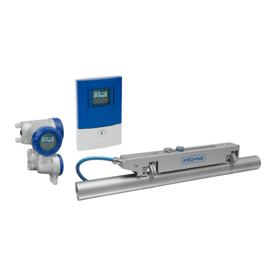
The ultrasonic clamp-on flowmeter can be fitted on the outside of piping to measure the flow rate of liquids. The device is a combination of one up to two clamp-on sensor(s) and one ultrasonic flow converter. Figure 2-2: System configuration possibilities www.krohne.com 07/2009 - 4000263902 - HB OPTISONIC 6300 R03 en... -
Page 13: Nameplates
2 Protection category 3 Calibration number 4 Process temperature (-40...+200°C for XT version) 5 Manufacturing year 6 Serial number 7 Device type (yyy = small, medium or large) 8 Manufacturer 07/2009 - 4000263902 - HB OPTISONIC 6300 R03 en www.krohne.com... -
Page 14: Signal Converter
1 Manufacturer 2 Device type 3 Manufacturing year 4 Serial number sensor 1 + short code flow sensor 5 Serial number sensor 2 + short code flow sensor 6 Empty www.krohne.com 07/2009 - 4000263902 - HB OPTISONIC 6300 R03 en... -
Page 15: Electrical Connection Data Of Inputs/Outputs (Example Of Basic Version)
• A = active mode; the signal converter supplies the power for connection of the subsequent devices • P = passive mode; external power supply required for operation of the subsequent devices • N/C = connection terminals not connected 07/2009 - 4000263902 - HB OPTISONIC 6300 R03 en www.krohne.com... -
Page 16: Installation
• Suitable for indoor and outdoor use and certified for operating up to an altitude of 2000 m / 6562 ft • IP class 66/67 CAUTION! The device should be protected from corrosive chemicals or gases and dust / particles accumulation. www.krohne.com 07/2009 - 4000263902 - HB OPTISONIC 6300 R03 en... -
Page 17: Installation Requirements Signal Converter
Additionally flow profile distortion is possible. CAUTION! If you program the diameter, please note that you use the outer diameter of the pipe. 07/2009 - 4000263902 - HB OPTISONIC 6300 R03 en www.krohne.com... -
Page 18: Inlet, Outlet And Recommended Mounting Area
• If not possible, ensure adequate velocity to prevent air, gas or vapor from collecting in upper part. • In partially filled pipes, the clamp-on flowmeter will report incorrect flow rates, or not measure. Figure 3-2: Long horizontal pipes www.krohne.com 07/2009 - 4000263902 - HB OPTISONIC 6300 R03 en... -
Page 19: Open Feed Or Discharge
Figure 3-4: Down going pipeline over 5 m /16 ft length 3.5.5 Position of control valve Always install control valves downstream of flowmeter in order to avoid cavitation or distortion of flow profile. Figure 3-5: Position of control valve 07/2009 - 4000263902 - HB OPTISONIC 6300 R03 en www.krohne.com... -
Page 20: Position Of Pump
3.5.7 Pipe diameters and sensor construction Figure 3-7: Measuring modes 1 Z-mode 2 V-mode 3 W-mode 3.5.8 Pipe and media parameters INFORMATION! Detailed databases of most pipe and media parameters are on the supplied CD. www.krohne.com 07/2009 - 4000263902 - HB OPTISONIC 6300 R03 en... -
Page 21: Installation Of The Flowmeter
Installation of the rails with the metal straps Installation of the rails with the metal straps Installation of the rails with the metal straps • 8: Repeat steps 1...7 at the other side of the rail. 07/2009 - 4000263902 - HB OPTISONIC 6300 R03 en www.krohne.com... - Page 22 • Slide the transducer 2 to the advised mounting distance 3 (menu X9.4). • Lock the transducer by turning the locking knob 1 clockwise. Greasing the transducer surfaces Greasing the transducer surfaces Greasing the transducer surfaces Greasing the transducer surfaces www.krohne.com 07/2009 - 4000263902 - HB OPTISONIC 6300 R03 en...
-
Page 23: Installation Instructions For Small And Medium Version
Figure 3-8: Procedure for installation of small or medium version 1 Rail, small version 2 Rail, medium version 3 Choose for V-mode or ... 4 Choose for W-mode 5 Make settings in converter 07/2009 - 4000263902 - HB OPTISONIC 6300 R03 en www.krohne.com... - Page 24 3 Small version: single pipe / dual path 4 Medium version: single pipe / dual path 5 Small version: dual pipe / single path 6 Medium version: dual pipe / single path www.krohne.com 07/2009 - 4000263902 - HB OPTISONIC 6300 R03 en...
-
Page 25: Installation Instructions For Large Version
1 Enter the values for the installation menu, X1...X9.8.4 2 Read the advised mounting distance in menu X9.8.5 3 Choose for Z-mode (default) or ... 4 Choose for V-mode 5 Finish the installation menu 07/2009 - 4000263902 - HB OPTISONIC 6300 R03 en www.krohne.com... - Page 26 INSTALLATION OPTISONIC 6300 Figure 3-11: Device versions 1 Single pipe, single path 2 Single pipe, dual path 3 Dual pipe www.krohne.com 07/2009 - 4000263902 - HB OPTISONIC 6300 R03 en...
-
Page 27: Mounting Of Converter
Each time a housing cover is opened, the thread should be cleaned and greased. Use only resin- free and acid-free grease. Ensure that the housing gasket is properly fitted, clean and undamaged. 07/2009 - 4000263902 - HB OPTISONIC 6300 R03 en www.krohne.com... -
Page 28: Mounting Of Ufc 300 W
• Position lock washers and nuts on the housing bolts, tighten nuts slightly. • Align housing, tighten nuts firmly. • Observe max. allowed length of 30 m / 98.4 ft for the signal cable. www.krohne.com 07/2009 - 4000263902 - HB OPTISONIC 6300 R03 en... -
Page 29: Electrical Connections
2 Cover, terminal compartment for power supply and inputs/outputs 3 Cable entry for power 4 Cable entry for inputs/outputs 5 Cable entry for sensor cable 6 Cover, sensor terminal compartment 07/2009 - 4000263902 - HB OPTISONIC 6300 R03 en www.krohne.com... -
Page 30: Ufc 300 W
2 Cover for the three separate terminal compartments for power, sensor connection and inputs/outputs 3 Locking screw, 1/2 turn left/right to open/close cover 2 4 Sensor terminal compartment 5 Terminal compartment for inputs/outputs 6 Power terminal compartment, open separate shock-hazard protection cover www.krohne.com 07/2009 - 4000263902 - HB OPTISONIC 6300 R03 en... -
Page 31: Electrical Connection
1 Put in the connector. 2 Turn knob to secure the connector. CAUTION! For XT versions: check if the signal cable is heat protected with the protection sleeve of 1 meter / 40". 07/2009 - 4000263902 - HB OPTISONIC 6300 R03 en www.krohne.com... - Page 32 1 Connect the blue cable to the UP rail. 2 Connect the green cable to the DOWN rail. 3 Make connections in cable box. 4 Cable to converter 5 Turn the screws clockwise to secure the caps. www.krohne.com 07/2009 - 4000263902 - HB OPTISONIC 6300 R03 en...
-
Page 33: Signal Cable And Power Supply Signal Converter
1 Connect blue cable to 1U (to 2U for 2 sensor) and the green cable to 1D (2D for 2 sensor) 2 Communication I/O 3 Power supply: 24 VAC/DC or 100...240 VAC 07/2009 - 4000263902 - HB OPTISONIC 6300 R03 en www.krohne.com... - Page 34 U-clamp terminal in the terminal compartment of the signal converter. • When connecting to functional extra-low voltages, provide a facility for protective separation (PELV) (VDE 0100 / VDE 0106 and/or IEC 364 / IEC 536 or relevant national regulations). www.krohne.com 07/2009 - 4000263902 - HB OPTISONIC 6300 R03 en...
-
Page 35: Laying Electrical Cables Correctly
2 Tighten the screw connection of the cable entry securely. 3 Never mount the housing with the cable entries facing upwards. 4 Seal cable entries that are not needed with a plug. 07/2009 - 4000263902 - HB OPTISONIC 6300 R03 en www.krohne.com... -
Page 36: Description Of The Electrical Symbols
Electronic or electromagnetic counter At frequencies above 100 Hz, shielded cables must be used to connect the counters. Internal resistance of the counter Button, NO contact or similar Table 4-1: Description of symbols www.krohne.com 07/2009 - 4000263902 - HB OPTISONIC 6300 R03 en... -
Page 37: Basic Inputs And Outputs
• 1 status output, • 1 control input. The pulse output can also be set as a status output. One of the status outputs can be set as a control input. 07/2009 - 4000263902 - HB OPTISONIC 6300 R03 en www.krohne.com... -
Page 38: Fixed, Non-Alterable Input/Output Versions
1 function changed by reconnection 2 changeable • The grey boxes in the tables denote unassigned or unused connection terminals. • Connection terminal A+ is only operable in the basic input/output version. www.krohne.com 07/2009 - 4000263902 - HB OPTISONIC 6300 R03 en... - Page 39 Signal converter monitors cable breaks and short circuits as per EN 60947-5-6. Errors indicated on LCD display. Error messages possible via status output. Active current input Passive current input No additional module installed No further module possible 07/2009 - 4000263902 - HB OPTISONIC 6300 R03 en www.krohne.com...
-
Page 40: Basic Inputs/Outputs
= 24 VDC nominal int,nom ≤ 32 VDC • U • I ≤ 22 mA ≥ 1.8 • U ≤ (U • R ) / I Figure 4-12: Current output passive I www.krohne.com 07/2009 - 4000263902 - HB OPTISONIC 6300 R03 en... - Page 41 ) / I L, min • Can also be set as a status output; for the electrical connection, see status output connection diagram. Figure 4-13: Pulse frequency output passive P 07/2009 - 4000263902 - HB OPTISONIC 6300 R03 en www.krohne.com...
- Page 42 Contact closed (on): U = 2.8 mA • Can also be set as a status output; for the electrical connection, see status output connection diagram. Figure 4-15: Control input passive C 1 Signal www.krohne.com 07/2009 - 4000263902 - HB OPTISONIC 6300 R03 en...
-
Page 43: Hart ® Connection
1 Basic I/O: terminals A and A+ 2 Modular I/O: terminals C- and C ® 3 HART communicator communicator must be R ≥ 230 Ω. ® The parallel resistance to the HART 07/2009 - 4000263902 - HB OPTISONIC 6300 R03 en www.krohne.com... -
Page 44: Modular Inputs And Outputs
2 option modules for term. A + B passive ® + HART passive 7 _ _ max. 2 option modules for term. A + B NAMUR ® + HART active www.krohne.com 07/2009 - 4000263902 - HB OPTISONIC 6300 R03 en... - Page 45 Signal converter monitors cable breaks and short circuits as per EN 60947-5-6. Errors indicated on LCD display. Error messages possible via status output. Active current input Passive current input No additional module installed No further module possible 07/2009 - 4000263902 - HB OPTISONIC 6300 R03 en www.krohne.com...
-
Page 46: Modular Inputs/Outputs And Bus Systems
≤ (U • R ) / I • X designates the connection terminals A, B or C, depending on the version of the signal converter. Figure 4-19: Current output passive I www.krohne.com 07/2009 - 4000263902 - HB OPTISONIC 6300 R03 en... - Page 47 ) / I L, min • X designates the connection terminals A, B or D, depending on the version of the signal converter. Figure 4-20: Pulse / frequency output active P 07/2009 - 4000263902 - HB OPTISONIC 6300 R03 en www.krohne.com...
- Page 48 • Can also be set as a status output; see status output connection diagram. • X designates the connection terminals A, B or D, depending on the version of the signal converter. Figure 4-21: Pulse frequency output passive P www.krohne.com 07/2009 - 4000263902 - HB OPTISONIC 6300 R03 en...
- Page 49 • X designates the connection terminals A, B or D, depending on the version of the signal converter. Figure 4-22: Pulse and frequency output passive P to NAMUR EN 60947-5-6 07/2009 - 4000263902 - HB OPTISONIC 6300 R03 en www.krohne.com...
- Page 50 • The output is open when the device is de-energized. • X designates the connection terminals A, B or D, depending on the version of the signal converter. Figure 4-24: Status output / limit switch passive S www.krohne.com 07/2009 - 4000263902 - HB OPTISONIC 6300 R03 en...
- Page 51 • X designates the connection terminals A, B or D, depending on the version of the signal converter. Figure 4-25: Status output / limit switch S to NAMUR EN 60947-5-6 07/2009 - 4000263902 - HB OPTISONIC 6300 R03 en www.krohne.com...
- Page 52 Contact closed (on): U = 1.9 mA • X designates the connection terminals A or B, depending on the version of the signal converter. Figure 4-27: Control input passive C 1 Signal www.krohne.com 07/2009 - 4000263902 - HB OPTISONIC 6300 R03 en...
- Page 53 ≤ 1.2 V with I ≥ 6.7 mA • X designates the connection terminals A or B, depending on the version of the signal converter. Figure 4-28: Control input active C to NAMUR EN 60947-5-6 07/2009 - 4000263902 - HB OPTISONIC 6300 R03 en www.krohne.com...
-
Page 54: Hart ® Connection
1 Basic I/O: terminals A and A+ 2 Modular I/O: terminals C- and C ® 3 HART communicator communicator must be R ≥ 230 Ω. ® The parallel resistance to the HART www.krohne.com 07/2009 - 4000263902 - HB OPTISONIC 6300 R03 en... - Page 55 Figure 4-30: HART connection passive (I 1 Basic I/O: terminals A- and A 2 Modular I/O: terminals C- and C ® 3 HART communicator ® 4 Other HART - capable devices 07/2009 - 4000263902 - HB OPTISONIC 6300 R03 en www.krohne.com...
-
Page 56: Start-Up
Esc (> + ↑) Return to menu mode Return to sub-menu or without acceptance of function without data acceptance of data Table 5-1: Description of key functionality www.krohne.com 07/2009 - 4000263902 - HB OPTISONIC 6300 R03 en... - Page 57 Start installation menu • Connect converter to power supply and power up converter. First and second page appear intermittently • Keep left button ">" pressed, until in display appears "release key now". 07/2009 - 4000263902 - HB OPTISONIC 6300 R03 en www.krohne.com...
- Page 58 > ↓ > fill in using ↑ ↓ > X6.13 viscosity > ↑ ↓ pipe data 2 > ↑ ↓ X7.1 copy pipe 1 data > start to copy ? www.krohne.com 07/2009 - 4000263902 - HB OPTISONIC 6300 R03 en...
- Page 59 (underneath X10 becomes active if two pipes or two paths (underneath X10 becomes active if two pipes or two paths are selected in X4 or X5) ↑ ↓ install transd. 2 > submenus identical to X9.1 up to X9.12 07/2009 - 4000263902 - HB OPTISONIC 6300 R03 en www.krohne.com...
-
Page 60: Start Measurement Of Small / Medium Version
• X9.12: End Installation? Enter "Yes" to save the installation. The measurement screen will appear. • Mount the cover (see the section "mounting the cover" in chapter "General mechanical installation") www.krohne.com 07/2009 - 4000263902 - HB OPTISONIC 6300 R03 en... -
Page 61: Start Measurement Of Large Version
• X9.7: Press enter • X9.8: Optimization loop. Enter "No" in X9.8.1 • X9.9: Press enter. Wait for 30 seconds • X9.10: Path ready? Enter "Yes" • X9.12: End Installation? Enter "Yes" 07/2009 - 4000263902 - HB OPTISONIC 6300 R03 en www.krohne.com... - Page 62 Advised distance [mm] Advised distance [mm] Transducer position [mm] Transducer position [mm] 100...250 >250 Figure 5-3: Device versions 1 Single pipe, single path 2 Single pipe, dual path 3 Dual pipe www.krohne.com 07/2009 - 4000263902 - HB OPTISONIC 6300 R03 en...
-
Page 63: Mechanical Installation For Large Version
Figure 5-4: Mounting the large rail 1 Align the UP rail with the pipeline. 2 Fixing units 3 Turn screws clockwise to secure. 4 Mark the position. 5 Cable box 07/2009 - 4000263902 - HB OPTISONIC 6300 R03 en www.krohne.com... - Page 64 5 Mount the cable box (only for downstream metal strap). 6 Push the metal strap through the upper slit of the fixing unit. 7 Pull the metal strap moderately tight by hand. • Secure by turning screws clockwise. www.krohne.com 07/2009 - 4000263902 - HB OPTISONIC 6300 R03 en...
- Page 65 2 Add the Advised Distance and mark the location on the alignment line. • Mount the DOWN rail in such a way that the transducer is at the marked location. 2. FIND THE LOCATION WITH THE SUPPLIED POSITIONING TOOL 07/2009 - 4000263902 - HB OPTISONIC 6300 R03 en www.krohne.com...
- Page 66 2 Outer diameter of pipeline INFORMATION! For large diameters you can use the weight of the metal plates to throw the cable around the pipe. First release one of the cables in that case! www.krohne.com 07/2009 - 4000263902 - HB OPTISONIC 6300 R03 en...
- Page 67 Repeat above steps to check if you find the same points. Figure 5-8: Marking the opposite location Calculate the middle of the alignment line between the 4 V-marks as shown. 07/2009 - 4000263902 - HB OPTISONIC 6300 R03 en www.krohne.com...
- Page 68 • Mount the DOWN rail in such a way that the transducer is at the marked location. • Grease all transducers, see "General mechanical installation". INFORMATION! It can be necessary to install the DOWN rail as shown below. www.krohne.com 07/2009 - 4000263902 - HB OPTISONIC 6300 R03 en...
- Page 69 Figure 5-10: Mounting large version in V-mode 1 Fixing units 2 Reference marking 3 Cable box 4 Advised Distance, X9.4 5 Minimum distance between UP and DOWN rail: 110 mm / 4.3" 07/2009 - 4000263902 - HB OPTISONIC 6300 R03 en www.krohne.com...
- Page 70 1 Connect blue cable to 1U (to 2U for 2 sensor) and the green cable to 1D (2D for 2 sensor) 2 Communication I/O 3 Power supply: 24 VAC/DC or 100...240 VAC www.krohne.com 07/2009 - 4000263902 - HB OPTISONIC 6300 R03 en...
- Page 71 Signal < 10%: Signal < 10%: Signal < 10%: Signal < 10%: bad or no signal, check settings in menu X6, increase transducer distance and/or go into the optimization loop. 07/2009 - 4000263902 - HB OPTISONIC 6300 R03 en www.krohne.com...
- Page 72 • X9.12: End Installation? If you enter "No" the installation is not saved, go to X9. If you enter "Yes" the installation is saved and the measurement screen will appear. • Mount the cover (see section "mounting the cover" in chapter "General mechanical installation") www.krohne.com 07/2009 - 4000263902 - HB OPTISONIC 6300 R03 en...
-
Page 73: Operation
IO Counter IO HART device INFORMATION! You find the description of the X Installation X Installation X Installation menu in Chapter 5 of this handbook X Installation 07/2009 - 4000263902 - HB OPTISONIC 6300 R03 en www.krohne.com... -
Page 74: Menu Structure
HART current output is selected if yes: all analog outputs are selected ↑ ↓ digital outputs > A5.1, A5.2,… A5.1 measurement > select from list using ↑ ↓ > www.krohne.com 07/2009 - 4000263902 - HB OPTISONIC 6300 R03 en... - Page 75 > ↑ ↓ use at all outputs yes/no if no: only pulse output D is selected if yes: all digital outputs are selected ↑ ↓ GDC IR interface > activate/cancel 07/2009 - 4000263902 - HB OPTISONIC 6300 R03 en www.krohne.com...
-
Page 76: Test
(additional menus for two pipes) ↑ ↓ B.2.3 act. Reynolds nr. > (additional menus for two pipes) ↑ ↓ B.2.4 act. vel. of sound > (additional menus for two pipes) www.krohne.com 07/2009 - 4000263902 - HB OPTISONIC 6300 R03 en... - Page 77 C number read ↑ ↓ B3.2 process input B3.2.1 sensor CPU read B3.2.2 sensor DSP read B3.2.3 sensor driver read ↑ ↓ B3.3 device sernr/swnr/yymm ↑ ↓ B3.4 display sernr/swnr/yymm 07/2009 - 4000263902 - HB OPTISONIC 6300 R03 en www.krohne.com...
-
Page 78: Setup
C1.10.1, C1.10.2,… C1.10.1 sensor CPU read C1.10.2 sensor DSP read C1.10.3 sensor driver read fill in using ↑ ↓ > C1.11 diagnosis value > ↑ ↓ process input 2 > www.krohne.com 07/2009 - 4000263902 - HB OPTISONIC 6300 R03 en... - Page 79 > ↑ ↓ C1.10 information > C1.10.1, C1.10.2,… C1.10.1 sensor CPU read C1.10.2 sensor DSP read C1.10.3 sensor driver read fill in using ↑ ↓ > C1.11 diagnosis value > 07/2009 - 4000263902 - HB OPTISONIC 6300 R03 en www.krohne.com...
- Page 80 ↑ ↓ > C5.3.3 100 % pulse rate > C5.3.4 measurement > select from list using ↑ ↓ fill in using ↑ ↓ > C5.3.5 range > www.krohne.com 07/2009 - 4000263902 - HB OPTISONIC 6300 R03 en...
- Page 81 Y > read: status off C5.5.7 control input Y > read: status off C5.5.8 > read: status off C5.5.9 invert signal > select on/off C5.5.10 information > read 07/2009 - 4000263902 - HB OPTISONIC 6300 R03 en www.krohne.com...
- Page 82 > read C7.1.3 HART dynamic > select from list using ↑ ↓ variable C7.2 SV is > C7.2.1 C7.2.1 HART dynamic > select from list using ↑ ↓ variable www.krohne.com 07/2009 - 4000263902 - HB OPTISONIC 6300 R03 en...
- Page 83 > C8.5.1, C8.5.2,… C8.5.1 select range > select manual/automatic fill in using ↑ ↓ > C8.5.2 range > fill in using ↑ ↓ > C8.5.3 time scale > 07/2009 - 4000263902 - HB OPTISONIC 6300 R03 en www.krohne.com...
- Page 84 > ↑ ↓ C8.9 quick setup > C8.9.1, C8.9.2,… C8.9.1 reset counter 1 > select yes/no C8.9.2 reset counter 2 > select yes/no C8.9.3 reset counter 3 > select yes/no www.krohne.com 07/2009 - 4000263902 - HB OPTISONIC 6300 R03 en...
-
Page 85: Customize Settings
↑ ↓ > X12.4 Tb calibration no. > fill in using ↑ ↓ > X12.5 Tc serial no. > fill in using ↑ ↓ > X12.6 Tc calibration no. > 07/2009 - 4000263902 - HB OPTISONIC 6300 R03 en www.krohne.com... -
Page 86: Function Description
HART current output (depends on pipe configuration: 1 or 2 pipes) volume flow, mass flow, VoS, flow speed, gain, SNR, diagnosis value, volume flow 1 or 2, VoS 1 or 2 www.krohne.com 07/2009 - 4000263902 - HB OPTISONIC 6300 R03 en... - Page 87 0.500 - 2.000 volume flow, mass flow, flow speed and Reynolds number C1.6.3 Reynolds set Reynolds correction for flow on,off correction profile disturbances, effective on volume flow, mass flow 07/2009 - 4000263902 - HB OPTISONIC 6300 R03 en www.krohne.com...
- Page 88 C5.2.10 time constant within set time, measurements min-max: 000.1 - 100.0 are averaged, displayed and sent to current output C5.2.11 special functions for ranging automatic range, external range, off www.krohne.com 07/2009 - 4000263902 - HB OPTISONIC 6300 R03 en...
- Page 89 00.0 - 20.0 C5.4.9 time constant within set time, measurements min-max: 000.1 - 100.0 are averaged, displayed and sent to current output C5.4.10 invert signal activate switch closed, open off, on 07/2009 - 4000263902 - HB OPTISONIC 6300 R03 en www.krohne.com...
- Page 90 C5.6.6 information serial number of circuit board, software version, calibration date of circuit board www.krohne.com 07/2009 - 4000263902 - HB OPTISONIC 6300 R03 en...
- Page 91 C7.3 TV is Third Variable C7.4 4V is Fourth Variable device device device device C8.2.2 contrast min-max: -9 - +9 C8.2.3 default display 1.meas.page, 2.meas.page, graphic page, status page, none 07/2009 - 4000263902 - HB OPTISONIC 6300 R03 en www.krohne.com...
- Page 92 ST, LT, free unit C8.7.7 density kg/L, kg/m3, lb/ft3, lb/gal, free unit C8.7.8 viscosity cSt, m2/s, mm2/s C8.8.1 HART factory setting: HART communication on; generates F: application error open circuit A www.krohne.com 07/2009 - 4000263902 - HB OPTISONIC 6300 R03 en...
-
Page 93: Error Messages
A current on current output A (or B, extend upper or lower limit for (or B, C) C) is limited by parameter setting current output in menu C5.2.8 07/2009 - 4000263902 - HB OPTISONIC 6300 R03 en www.krohne.com... - Page 94 DSP and error microprocessor software www.krohne.com 07/2009 - 4000263902 - HB OPTISONIC 6300 R03 en...
-
Page 95: Service
Clean pipe and contact surfaces of transducers with a soft cloth. • Regrease the contact surfaces of transducers 4. • Turn rail 90 degrees back 5. • Press rail at both ends to the pipe by clicking 6. 07/2009 - 4000263902 - HB OPTISONIC 6300 R03 en www.krohne.com... -
Page 96: Cleaning
Only the sensor calibration data are loaded. - if in the screen appears “load no data load no data load no data”, all data have been lost. Contact your local load no data representative. www.krohne.com 07/2009 - 4000263902 - HB OPTISONIC 6300 R03 en... -
Page 97: Field Version
CAUTION! Please pay attention that the same amount of force is applied on both pullers, otherwise the connector at the backside can be damaged. 07/2009 - 4000263902 - HB OPTISONIC 6300 R03 en www.krohne.com... - Page 98 • Screw the electronics unit back to the housing. • Re-install the display and make sure not to kink the display's flat ribbon cable. • Replace cover and tighten by hand. • Connect power. www.krohne.com 07/2009 - 4000263902 - HB OPTISONIC 6300 R03 en...
-
Page 99: Wall Version
• Turn locking screw to the left 1 to unlock the lower door. • Open lower door. • Slide metal slider, positioned at the left upper angle, downwards. • Open upper door 2. 07/2009 - 4000263902 - HB OPTISONIC 6300 R03 en www.krohne.com... - Page 100 • Unscrew the two M4 screws 7 at the electronics unit 5. Figure 7-7: Release printed circuit board • Remove the small printed circuit board 6with care. • Carefully slide the electronics unit 5, then lift it out of the housing. www.krohne.com 07/2009 - 4000263902 - HB OPTISONIC 6300 R03 en...
- Page 101 • Close and lock the lower door. • Connect power. CAUTION! First program the installation menu, refer to General instructions for programming on page 56 and check all important settings. 07/2009 - 4000263902 - HB OPTISONIC 6300 R03 en www.krohne.com...
-
Page 102: Replacing The Mains Fuse
0.8AT/H/250 , breaking capacity 1500 A at 250 V • 24 VAC/DC power supply: 24 VAC/DC power supply: 24 VAC/DC power supply: 24 VAC/DC power supply: 2AT/H/250 , breaking capacity 1500 A at 250 V www.krohne.com 07/2009 - 4000263902 - HB OPTISONIC 6300 R03 en... -
Page 103: Field Version
• Mount the small printed circuit board back onto the sensor driver board. • Put the electronics unit back to the housing. • Click the display back into the holders. • Close the housing and lock the doors. • Connect power. 07/2009 - 4000263902 - HB OPTISONIC 6300 R03 en www.krohne.com... -
Page 104: Spare Parts Availability
• such dangerous substances, to enclose a certificate with the device confirming that is safe to handle and stating the • product used. www.krohne.com 07/2009 - 4000263902 - HB OPTISONIC 6300 R03 en... -
Page 105: Form (For Copying) To Accompany A Returned Device
We hereby confirm that there is no risk to persons or the environment through any residual media contained in the device when it is returned. Date: Signature: Stamp: 7.8 Disposal CAUTION! Disposal must be carried out in accordance with legislation applicable in your country. 07/2009 - 4000263902 - HB OPTISONIC 6300 R03 en www.krohne.com... -
Page 106: Technical Data
• The difference in transit time is directly proportional to the mean flow velocity of the medium. Figure 8-1: Measuring principle 1 Transducer A 2 Transducer B 3 Flow velocity 4 Transit time from transducer A to B 5 Transit time from transducer B to A www.krohne.com 07/2009 - 4000263902 - HB OPTISONIC 6300 R03 en... -
Page 107: Technical Data
2 internal counters with a max. of 8 counter places (e.g. for counting volume and/or mass units) Self diagnostics Integrated verification, diagnosis functions: flowmeter, process, measured value, empty pipe detection, bargraph 07/2009 - 4000263902 - HB OPTISONIC 6300 R03 en www.krohne.com... - Page 108 Metal, plastic, ceramic, asbestos cement, internal / external coated pipes (coatings and liners fully bonded to pipe wall) Pipewall thickness < 200 mm / 7.87" Liner thickness < 20 mm / 0.79" www.krohne.com 07/2009 - 4000263902 - HB OPTISONIC 6300 R03 en...
- Page 109 2 internal triax, available lengths: 5 m / 15 ft (standard), maximum length 30 m / 90 ft Cable entries Standard: M20 x 1.5 Option: ½" NPT, PF ½ 07/2009 - 4000263902 - HB OPTISONIC 6300 R03 en www.krohne.com...
- Page 110 ≥ 250 Ω Load Please observe maximum value for current output Multidrop Yes, current output = 4 mA Multidrop addresses programmable in menu 1...15 Device drivers FDT/DTM www.krohne.com 07/2009 - 4000263902 - HB OPTISONIC 6300 R03 en...
- Page 111 = 0.6 mA open: I = 0.43 mA closed: I = 3.8 mA closed: I = 4.5 mA = 30 V = 100 mA = 1 W =10 nF ~ 0 mH 07/2009 - 4000263902 - HB OPTISONIC 6300 R03 en www.krohne.com...
- Page 112 = 0.6 mA open: I = 0.43 mA closed: I = 3.8 mA closed: I = 4.5 mA = 30 V = 100 mA = 1 W =10 nF = 0 mH www.krohne.com 07/2009 - 4000263902 - HB OPTISONIC 6300 R03 en...
- Page 113 Can be set together for all flow indicators and outputs, or separately for: current, pulse and frequency output, and for limit switches and the 3 internal counters Time setting 0…100 seconds, settable in 0.1 second steps 07/2009 - 4000263902 - HB OPTISONIC 6300 R03 en www.krohne.com...
- Page 114 Other approvals and standards Other approvals and standards Other approvals and standards Electromagnetic compatibility Directive: 89/336/EEC, NAMUR NE21/04 Harmonized standard: EN 61326-1: 2006 Low Voltage Directive Directive: 2006/95/EC Harmonized standard: EN 61010: 2001 www.krohne.com 07/2009 - 4000263902 - HB OPTISONIC 6300 R03 en...
-
Page 115: Dimensions And Weights
Dimensions and weights in mm and kg Version Dimensions [mm] Weights [kg] 295.8 Dimensions and weights in inches and lbs Version Dimensions [inches] Weights [lbs] 7.75 4.75 6.10 11.60 10.90 12.60 7.80 5.40 11.80 5.30 07/2009 - 4000263902 - HB OPTISONIC 6300 R03 en www.krohne.com... -
Page 116: Clamp-On Sensor And Cable Box
32.5 Large 19.5 Small - stainless 19.4 steel / XT Medium - stainless 32.4 steel / XT 1 value for one of the 2 delivered rails 2 delivered without cover www.krohne.com 07/2009 - 4000263902 - HB OPTISONIC 6300 R03 en... - Page 117 TECHNICAL DATA OPTISONIC 6300 Dimensions [mm] Approx. weight without cable/metal [kg] Cable box 0.85 Dimensions [inches] Approx. weight without cable/metal [lbs] Cable box 4.01 7.76 2.64 1.87 07/2009 - 4000263902 - HB OPTISONIC 6300 R03 en www.krohne.com...
-
Page 118: Mounting Plate, Field Housing
OPTISONIC 6300 8.3.3 Mounting plate, field housing Dimensions in mm and inches [mm] [inches] Ø9 Ø0.4 8.3.4 Mounting plate, wall-mounted housing Dimensions in mm and inches [mm] [inches] Ø9 Ø0.4 3.85 www.krohne.com 07/2009 - 4000263902 - HB OPTISONIC 6300 R03 en... - Page 119 NOTES OPTISONIC 6300 07/2009 - 4000263902 - HB OPTISONIC 6300 R03 en www.krohne.com...
- Page 120 Measuring systems for sea-going tankers Head Office KROHNE Messtechnik GmbH & Co. KG Ludwig-Krohne-Str. 5 D-47058 Duisburg (Germany) Tel.:+49 (0)203 301 0 Fax:+49 (0)203 301 10389 info@krohne.de The current list of all KROHNE contacts and addresses can be found at: www.krohne.com...
Need help?
Do you have a question about the OPTISONIC 6300 and is the answer not in the manual?
Questions and answers