KROHNE Optisonic 6300 Manual
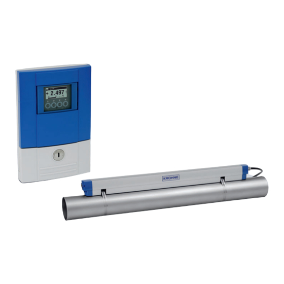
Ultrasonic clamp-on flowmeter for liquids
Hide thumbs
Also See for Optisonic 6300:
- Handbook (212 pages) ,
- Quick start manual (56 pages) ,
- Technical data sheet (44 pages)
Table of Contents
Advertisement
OPTISONIC 6300
OPTISONIC 6300
OPTISONIC 6300
OPTISONIC 6300
Ultrasonic clamp-on flowmeter for liquids
•
Robust sensor rail design for accurate and easy installation
•
Advanced diagnostics for verified operation
•
Factory calibrated sensors for optimal start-up and performance
© KROHNE 09/2020 - 4006413102 - TD OPTISONIC 6300 V2 R02 en
Technical Datasheet
Technical Datasheet
Technical Datasheet
Technical Datasheet
Advertisement
Table of Contents

Related Manuals for KROHNE Optisonic 6300


Summary of Contents for KROHNE Optisonic 6300
- Page 1 Ultrasonic clamp-on flowmeter for liquids • Robust sensor rail design for accurate and easy installation • Advanced diagnostics for verified operation • Factory calibrated sensors for optimal start-up and performance © KROHNE 09/2020 - 4006413102 - TD OPTISONIC 6300 V2 R02 en...
-
Page 2: Table Of Contents
3.15 Installation for energy measurement ................37 3.16 Installation of the converter ..................38 3.16.1 Pipe mounting ........................38 3.16.2 Wall mounting ........................39 3.16.3 Turning the display of the field housing version ..............41 www.krohne.com 09/2020 - 4006413102 - TD OPTISONIC 6300 V2 R02 en... - Page 3 4.5.1 Combinations of the inputs/outputs (I/Os) ................51 4.5.2 Description of the CG-number....................52 4.5.3 Fixed, non-alterable input/output versions................53 4.5.4 Alterable input/output versions.................... 54 5 Application form 6 Notes 09/2020 - 4006413102 - TD OPTISONIC 6300 V2 R02 en www.krohne.com...
-
Page 4: Product Features
OPTISONIC 6300 is the stationary ultrasonic clamp-on flowmeter for liquid applications. The OPTISONIC 6300 OPTISONIC 6300 specific KROHNE design of the sensor rails guarantees the user always simple and quick installation with the highest possible performance. The system consists of adjustable sensor rail(s) with the most clever designed fixing units for simple installation and maintenance in combination with industrial designed and approved ultrasonic flow converters. - Page 5 • Heat consumption/ energy measurement • Refined hydrocarbons • Potable water • De-ionized and demineralized water • Sanitary flow rate measurements • Purified water • HVAC • Acids, toxins and corrosives 09/2020 - 4006413102 - TD OPTISONIC 6300 V2 R02 en www.krohne.com...
-
Page 6: Variants
PRODUCT FEATURES OPTISONIC 6300 1.2 Variants The OPTISONIC 6300 OPTISONIC 6300 flowmeter consist of a small, medium or large rail(s) containing the OPTISONIC 6300 OPTISONIC 6300 ultrasonic transducers in combination with an ultrasonic signal converter: OPTISONIC 6000 (sensor rail) + UFC 300 (Ultrasonic Flow Converter) = OPTISONIC 6300... - Page 7 OPTISONIC 6300 Single and dual path configuration The OPTISONIC 6300 flowmeter uses the UFC 300 ultrasonic signal converter which is designed to control one or two measuring paths continuously. The two paths can be used as a dual path measurement on a single pipe for maximum reliability, or as two flowmeters on two separate pipes for maximum flexibility.
- Page 8 • Robust industrial field version • Die-cast epoxy coated aluminum or stainless steel housing • For hazardous and non hazardous area (Ex and non Ex) • IP66/67, NEMA 4X/6 www.krohne.com 09/2020 - 4006413102 - TD OPTISONIC 6300 V2 R02 en...
-
Page 9: Features
The measurement accuracy is largely determined by the quality of the installation of the clamp- on flow sensor which must be precisely installed and properly aligned. The OPTISONIC 6300 sensor is always provided with in-rail mounted transducers. A rail allows for accurate fixation of the transducer distance, guaranteeing their proper alignment. - Page 10 - via all communication protocols - Status messages are grouped by problem Out of specification source Unreliability of output signal - User can change group or priority Maintenance required Output signal still valid www.krohne.com 09/2020 - 4006413102 - TD OPTISONIC 6300 V2 R02 en...
-
Page 11: Options
OPTISONIC 6300 1.4 Options Energy (heat/cold) measurement The OPTISONIC 6300 standalone energy measurement feature can be used for cooling and heating applications. Using one or two temperature sensors connected directly to the signal converter. Thermal power and totalised energy are available on the display and as an output signal. -
Page 12: Measuring Principle
Figure 1-8: Measuring principle (example reflected path set-up) 1 Transducer A 2 Transducer B 3 Flow velocity 4 Transit time from transducer A to B 5 Transit time from transducer B to A www.krohne.com 09/2020 - 4006413102 - TD OPTISONIC 6300 V2 R02 en... -
Page 13: Technical Data
Verification and self-diagnostics Integrated verification, diagnostic functions: measuring device, process, measured values, device configuration, empty pipe detection, bar graph etc. Communication interfaces ® HART 7, Foundation Fieldbus, Profibus, Modbus RS485 (option). 09/2020 - 4006413102 - TD OPTISONIC 6300 V2 R02 en www.krohne.com... - Page 14 < ± 3% of the actual measured flow rate; for 0.5…20 m/s / 1.64…65.6 ft/s < ± 15 mm/s / 0.6 inch/s for 0.1…0.5 m/s / 0.33…1.64 ft/s. ± 0.2% Repeatability www.krohne.com 09/2020 - 4006413102 - TD OPTISONIC 6300 V2 R02 en...
- Page 15 Single path, single pipe or dual-path/dual-pipe Inlet run 10 DN straight length Outlet run 5 DN straight length Dimensions and weight Dimensions and weights For detailed information refer to on page 25. 09/2020 - 4006413102 - TD OPTISONIC 6300 V2 R02 en www.krohne.com...
- Page 16 Coating: standard and offshore coating Cable Double shielded coax cables Outer jacket: Polyester elastomer Cable glands Standard: nickel plated brass for cable 8-12 mm For Extended temperature / Offshore: stainless steel 316 L www.krohne.com 09/2020 - 4006413102 - TD OPTISONIC 6300 V2 R02 en...
- Page 17 To connect two sets of large rails a cable (splitter) box with an extension cable is required. Cable entries 1 or 2 cable entries for signal cables per flow converter Standard: M20 x 1.5 (8...12 mm) Option: ½" NPT; PF ½ 09/2020 - 4006413102 - TD OPTISONIC 6300 V2 R02 en www.krohne.com...
- Page 18 Multidrop Yes, current output = 10% e.g. 4 mA Multidrop addresses adjustable in operation menu 0...63 Device drivers DD for FC 375/475, AMS, PDM, DTM for FDT. www.krohne.com 09/2020 - 4006413102 - TD OPTISONIC 6300 V2 R02 en...
- Page 19 I = 0.43 mA closed: I = 3.8 mA closed: I = 4.5 mA = 30 V = 100 mA = 1 W = 10 nF ~ 0 mH 09/2020 - 4006413102 - TD OPTISONIC 6300 V2 R02 en www.krohne.com...
- Page 20 I = 0.43 mA closed: I = 3.8 mA closed: I = 4.5 mA = 30 V = 100 mA = 1 W = 10 nF = 0 mH www.krohne.com 09/2020 - 4006413102 - TD OPTISONIC 6300 V2 R02 en...
- Page 21 = 6.3 V with 0, nom = 1.9 mA Identification for open terminals: 8.1 V with I 0.1 mA Identification for short circuited terminals: 1.2 V with I 6.7 mA 09/2020 - 4006413102 - TD OPTISONIC 6300 V2 R02 en www.krohne.com...
- Page 22 Function blocks 4 x analogue input, 2 x integrator, 1 x PID Output data Volume flow, mass flow, flow speed, electronic temperature, velocity of sound, gain, SNR Diagnostic data www.krohne.com 09/2020 - 4006413102 - TD OPTISONIC 6300 V2 R02 en...
- Page 23 = 5 V 0, min at I 22 mA ® = 30 V No HART = 100 mA = 1 W = 10 nF = 0 mH ® No HART 09/2020 - 4006413102 - TD OPTISONIC 6300 V2 R02 en www.krohne.com...
- Page 24 Flow sensors Flow sensors Stainless steel version: IP66/67 or IP68 Shock resistance IEC 60068-2-27 30 g for 18 ms Vibration resistance IEC 60068-2-6 1 g up to 2000 Hz www.krohne.com 09/2020 - 4006413102 - TD OPTISONIC 6300 V2 R02 en...
-
Page 25: Dimensions And Weight
10.90 13.2 7.80 5.40 11.80 Table 2-2: Dimensions and weight in inch and lb The weight of the F version in stainless steel is 13.5 kg / 29.8 lb. 09/2020 - 4006413102 - TD OPTISONIC 6300 V2 R02 en www.krohne.com... -
Page 26: Clamp-On Sensor Rail
(without cable/strip) [lbs] Small 16.2 Medium 29.2 Large 16.2 Table 2-4: Dimensions and weight clamp-on sensor rail(s) [inch - lb] 1 value for one of the 2 delivered rails www.krohne.com 09/2020 - 4006413102 - TD OPTISONIC 6300 V2 R02 en... - Page 27 Table 2-5: Dimensions and weight cable box [mm - kg] Dimensions [inches] Approximately weight without cable [lbs] Cable box 4.53 8.27 2.64 Table 2-6: Dimensions and weight cable box [inch - lb] 09/2020 - 4006413102 - TD OPTISONIC 6300 V2 R02 en www.krohne.com...
-
Page 28: Mounting Plate Of Field Housing
Table 2-7: Dimensions in mm and inch 2.2.4 Mounting plate of wall-mounted housing Figure 2-5: Dimensions of mounting plate of wall-mounted housing [mm] [inch] Ø9 Ø0.4 3.85 Table 2-8: Dimensions in mm and inch www.krohne.com 09/2020 - 4006413102 - TD OPTISONIC 6300 V2 R02 en... -
Page 29: Installation
The manufacturer is not liable for any damage resulting from improper use or use for other than the intended purpose. The OPTISONIC 6300 is an ultrasonic clamp-on flowmeter that can be fitted on the outside of the pipeline to measure the flow rate of liquids. - Page 30 • piece of cloth. Coupling grease on the converter housing may be removed using soapy water. The device should be protected from corrosive chemicals or gases and dust/particles accumulation. www.krohne.com 09/2020 - 4006413102 - TD OPTISONIC 6300 V2 R02 en...
-
Page 31: Installation Conditions
After installation, the sensor can be completely insulated. The signal cable must be protected • correctly and kept away from the hot pipe surface. Always use the correct Personal Protective Equipment (heat-protection, gloves). • 09/2020 - 4006413102 - TD OPTISONIC 6300 V2 R02 en www.krohne.com... -
Page 32: Horizontal (Long) Pipes
25 DN 2 dimensional bends occur in a vertical or or or or horizontal plane (X/Y) only, while 3 dimensional bends occur in both vertical and and horizontal plane (X/Y/Z). www.krohne.com 09/2020 - 4006413102 - TD OPTISONIC 6300 V2 R02 en... -
Page 33: Bends
Vertical installation with a controlled back-pressure is possible. Figure 3-5: Installation in bending pipes (45°) NOTE! Vertical installation on a descending slope in the pipeline is only recommended when the back- pressure is controlled. 09/2020 - 4006413102 - TD OPTISONIC 6300 V2 R02 en www.krohne.com... -
Page 34: T-Section
A clamp-on flowmeter can be installed in the suction line of a pump if there is no cavitation in the pipeline system. www.krohne.com 09/2020 - 4006413102 - TD OPTISONIC 6300 V2 R02 en... -
Page 35: Position Of Control Valve
DN50...1250 / 2...50" X-mode (2 x 1 traverses) Large DN200...2000 / 8...80" Large: V mode (2 traverses) DN200...4000 / 8...160" Z-mode (1 traverse) Table 3-1: Version and preferred measuring mode 09/2020 - 4006413102 - TD OPTISONIC 6300 V2 R02 en www.krohne.com... -
Page 36: Installation Instructions For X Mode Configuration
• Set menu item X7.4 = transducer distance the exact distance between up transducer of Ta to the down transducer of Tb • Repeat the process for transducer 2 www.krohne.com 09/2020 - 4006413102 - TD OPTISONIC 6300 V2 R02 en... -
Page 37: Installation For Energy Measurement
3 PT 100 temperature sensor with 4-20 mA transmitter, downstream of the heat/cold producer/consumer 4 Observed heating or cooling object 5 UFC 300 signal converter Please find more detailed information in the OPTISONIC 6300 manual. 09/2020 - 4006413102 - TD OPTISONIC 6300 V2 R02 en www.krohne.com... -
Page 38: Installation Of The Converter
Figure 3-13: Pipe mounting of the field housing 1 Fix the signal converter to the pipe. 2 Fasten the signal converter using standard U-bolts and washers. 3 Tighten the nuts. www.krohne.com 09/2020 - 4006413102 - TD OPTISONIC 6300 V2 R02 en... -
Page 39: Wall Mounting
4 Screw the signal converter to the mounting plate with the nuts and washers. Figure 3-15: Mounting multiple devices next to each other a 600 mm / 23.6" b 250 mm / 9.8" 09/2020 - 4006413102 - TD OPTISONIC 6300 V2 R02 en www.krohne.com... - Page 40 2 Fasten the mounting plate securely to the wall. 3 Screw the signal converter to the mounting plate with the nuts and washers. Figure 3-17: Mounting multiple devices next to each other a 240 mm / 9.4" www.krohne.com 09/2020 - 4006413102 - TD OPTISONIC 6300 V2 R02 en...
-
Page 41: Turning The Display Of The Field Housing Version
Each time a housing cover is opened, the thread should be cleaned and greased. Use only resin- free and acid-free grease. Ensure that the housing gasket is properly fitted, clean and undamaged. 09/2020 - 4006413102 - TD OPTISONIC 6300 V2 R02 en www.krohne.com... -
Page 42: Electrical Connections
2 Tighten the screw connection of the cable entry securely. 3 Never mount the housing with the cable entries facing upwards. 4 Seal cable entries that are not needed with a plug. www.krohne.com 09/2020 - 4006413102 - TD OPTISONIC 6300 V2 R02 en... -
Page 43: Electrical Connections Signal Converter
3 Power supply: 24 VAC/DC or 100...230 VAC This is a Class A product. In a domestic environment this product may cause radio interference in which case the user may be required to take adequate measures. 09/2020 - 4006413102 - TD OPTISONIC 6300 V2 R02 en www.krohne.com... -
Page 44: Power Supply
(PELV) (acc. to VDE 0100 / VDE 0106 and/or IEC 60364 / IEC 61140 or relevant national regulations). For 24 VDC, 12 VDC-10% is included in the tolerance range. www.krohne.com 09/2020 - 4006413102 - TD OPTISONIC 6300 V2 R02 en... -
Page 45: Signal Converter Power Supply Connections
4.4.1 Signal converter power supply connections Field version (L+) / L (L-) / N Figure 4-5: Signal converter field version, power supply connections Wall version Figure 4-6: Signal converter wall version, power supply 09/2020 - 4006413102 - TD OPTISONIC 6300 V2 R02 en www.krohne.com... -
Page 46: Signal Cable To Converter
Excessive dis- / re-connection and/or positioning the connectors skewed to each other will damage the inside clips of the connectors. This results in an improper contact and measurement errors. www.krohne.com 09/2020 - 4006413102 - TD OPTISONIC 6300 V2 R02 en... - Page 47 1 path / 1 pipe Downstream U or 2.1 / Blue 2 path / 2 pipes Upstream D or 2.2 / Green 2 path / 2 pipes Downstream not connected not connected 09/2020 - 4006413102 - TD OPTISONIC 6300 V2 R02 en www.krohne.com...
- Page 48 U or 1.2 / Blue 2 path / 2 pipes Upstream D or 2.1 / Green 1 path / 1 pipe Downstream D or 2.2 / Green 2 path / 2 pipes Downstream www.krohne.com 09/2020 - 4006413102 - TD OPTISONIC 6300 V2 R02 en...
-
Page 49: Example Of Connecting The Cable Extension (Splitter) Box
Figure 4-12: Example of large sensor rail connections with cable (splitter) box 1 Cable (spitter) box connections 2 Installed UP rail 3 Installed DOWN rail 4 Extension cable to UFC 300 signal converter 09/2020 - 4006413102 - TD OPTISONIC 6300 V2 R02 en www.krohne.com... -
Page 50: Modular Inputs/Outputs Connections
• Push the prepared cable through the cable entry 2 and connect the necessary conductors 3. • Connect the shield if necessary 4. • Close the cover of the terminal compartment. • Lock 5 the housing cover with screw driver (counter clockwise). www.krohne.com 09/2020 - 4006413102 - TD OPTISONIC 6300 V2 R02 en... -
Page 51: Combinations Of The Inputs/Outputs (I/Os)
• For hazardous areas, all of the input/output variants with terminal compartment in the Ex d (pressure-resistant casing) or Ex e (increased safety) versions can be delivered. • Please refer to the separate instructions for connection and operation of the Ex-devices. 09/2020 - 4006413102 - TD OPTISONIC 6300 V2 R02 en www.krohne.com... -
Page 52: Description Of The Cg-Number
EN 60947-5-6. Errors indicated on LC display. Error messages possible via status output. Active current input Passive current input 2 x IIn Two active current inputs (for Ex i I/O) No additional module installed No further module possible www.krohne.com 09/2020 - 4006413102 - TD OPTISONIC 6300 V2 R02 en... -
Page 53: Fixed, Non-Alterable Input/Output Versions
1 Function changed by reconnecting 2 Changeable • The grey boxes in the tables denote unassigned or unused connection terminals. • Connection terminal A+ is only operable in the basic input/output version. 09/2020 - 4006413102 - TD OPTISONIC 6300 V2 R02 en www.krohne.com... -
Page 54: Alterable Input/Output Versions
V/D- (1) Modbus (option) G _ _ max. 2 optional modules for term. A + B Common Sign. B Sign. A (D1) (D0) 1 Changeable 2 Not activated bus terminator www.krohne.com 09/2020 - 4006413102 - TD OPTISONIC 6300 V2 R02 en... -
Page 55: Application Form
Normal: Maximum: Continuous / pulsating flow. Description: Entrained air percentage (volume): Entrained solids percentage (volume): Emulsion present (e.g. oil / water): Emulsion percentage product A: Emulsion percentage product B: 09/2020 - 4006413102 - TD OPTISONIC 6300 V2 R02 en www.krohne.com... - Page 56 Power supply (voltage, AC / DC): Analog output (4-20 mA): Pulse (specify minimum pulse width, pulse value): Digital protocol: Options: Remote mounted signal converter: specify cable length: Accessories: www.krohne.com 09/2020 - 4006413102 - TD OPTISONIC 6300 V2 R02 en...
-
Page 57: Notes
NOTES OPTISONIC 6300 09/2020 - 4006413102 - TD OPTISONIC 6300 V2 R02 en www.krohne.com... - Page 58 NOTES OPTISONIC 6300 www.krohne.com 09/2020 - 4006413102 - TD OPTISONIC 6300 V2 R02 en...
- Page 59 NOTES OPTISONIC 6300 09/2020 - 4006413102 - TD OPTISONIC 6300 V2 R02 en www.krohne.com...
- Page 60 Engineering, commissioning, calibration, maintenance and training services Head Office KROHNE Messtechnik GmbH Ludwig-Krohne-Str. 5 47058 Duisburg (Germany) Tel.: +49 203 301 0 Fax: +49 203 301 10389 info@krohne.com The current list of all KROHNE contacts and addresses can be found at: www.krohne.com...
Need help?
Do you have a question about the Optisonic 6300 and is the answer not in the manual?
Questions and answers