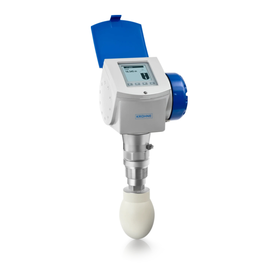
KROHNE OPTIWAVE 6300 C Technical Data Sheet
Non-contact radar (fmcw) level meter for solids
Hide thumbs
Also See for OPTIWAVE 6300 C:
- Handbook (128 pages) ,
- Supplementary instructions manual (28 pages) ,
- Quick start manual (28 pages)
Table of Contents
Advertisement
Quick Links
OPTIWAVE 6300 C
OPTIWAVE 6300 C
OPTIWAVE 6300 C
OPTIWAVE 6300 C
Non-contact Radar (FMCW) Level Meter for Solids
•
One converter for all antenna types (PTFE Drop, PP Drop and metallic horn)
•
The only guarantee for measuring accurately in dusty conditions
•
Uses a unique Drop antenna design for very dusty atmospheres
© KROHNE 04/2011 - 4000305604 - TD OPTIWAVE 6300 R04 en
Technical Datasheet
Technical Datasheet
Technical Datasheet
Technical Datasheet
Advertisement
Table of Contents

Related Manuals for KROHNE OPTIWAVE 6300 C


Summary of Contents for KROHNE OPTIWAVE 6300 C
- Page 1 One converter for all antenna types (PTFE Drop, PP Drop and metallic horn) • The only guarantee for measuring accurately in dusty conditions • Uses a unique Drop antenna design for very dusty atmospheres © KROHNE 04/2011 - 4000305604 - TD OPTIWAVE 6300 R04 en...
-
Page 2: Table Of Contents
CONTENTS OPTIWAVE 6300 C 1 Product features 1.1 The radar solution for solids .................... 3 1.2 Options..........................5 1.3 Measuring principle......................6 2 Technical data 2.1 Technical data........................7 2.2 Antenna selection ......................13 2.3 Guidelines for maximum operating pressure..............14 2.4 Dimensions and weights .................... -
Page 3: Product Features
PRODUCT FEATURES OPTIWAVE 6300 C 1.1 The radar solution for solids This device is a non-contact Radar (FMCW) Level Meter for distance, level, volume and mass measurement of powders, granulates and other solids. It gives a stabler measurement than pulse radar and is well suited to dusty process conditions. The device can operate at very low and very high process temperatures as long as the process connection temperature limits are observed. - Page 4 PRODUCT FEATURES OPTIWAVE 6300 C Highlights • ±10 mm / ±0.4¨ standard accuracy • PP or PTFE Drop antenna: its shape prevents product build-up in dusty applications • Operates up to a flange temperature of 200°C / 390°F and 40 bar / 580 psig •...
-
Page 5: Options
PRODUCT FEATURES OPTIWAVE 6300 C 1.2 Options Drop antennas Drop antennas are a unique innovation to measure powders and other solids in very dusty atmospheres. The ellipsoidal shape of the antennas prevents build-up and generates a small beam angle for accurate measurement of silo contents. -
Page 6: Measuring Principle
PRODUCT FEATURES OPTIWAVE 6300 C 1.3 Measuring principle A radar signal is emitted via an antenna, reflected from the product surface and received after a time t. The radar principle used is FMCW (Frequency Modulated Continuous Wave). The FMCW-radar transmits a high frequency signal whose frequency increases linearly during the measurement phase (called the frequency sweep). -
Page 7: Technical Data
TECHNICAL DATA OPTIWAVE 6300 C 2.1 Technical data The following data is provided for general applications. If you require data that is more • relevant to your specific application, please contact us or your local representative. Additional information (certificates, special tools, software,...) and complete product •... - Page 8 TECHNICAL DATA OPTIWAVE 6300 C Measurement accuracy Resolution 1 mm / 0.04¨ Repeatability ±5 mm / ±0.2¨ Accuracy ±10 mm / ±0.4¨, when distance < 10 m / 33 ft; ±0.1% of measured distance, when distance > 10 m / 33 ft Reference conditions acc.
- Page 9 TECHNICAL DATA OPTIWAVE 6300 C Installation conditions Process connection size The nominal diameter (DN) should be equal to or larger than the antenna diameter. If the nominal diameter (DN) is smaller than the antenna, either: - provide the means to adapt the device to a larger process connection on the silo...
- Page 10 TECHNICAL DATA OPTIWAVE 6300 C Electrical connections Power supply Terminals output 1 - Non-Ex / Ex i: Terminals output 1 - Non-Ex / Ex i: Terminals output 1 - Non-Ex / Ex i: Terminals output 1 - Non-Ex / Ex i: 14…30 VDC;...
- Page 11 TECHNICAL DATA OPTIWAVE 6300 C Physical layer types Standard power signaling, bus powered, non I.S. Other features Bus interface with integrated reverse polarity protection Device power supply (24 V input) 18...30 VDC Bus power supply 9...32 VDC (non-Ex); 9...17.5 VDC (intrinsically-safe)
- Page 12 TECHNICAL DATA OPTIWAVE 6300 C NEPSI Ex dia IIC T3~T6 DIP A21/A20 T T70°C~T95°C IP6X; Ex ia IIC T3~T6 DIP A21/A20 T T70°C~T95°C IP6X CEPEL / INMETRO BR-Ex ia IIC T6…T3 Ga CEPEL-EX-1996/11X Ex ia IIIC T95°C Da IP67 BR-Ex d[ia] IIC T6…T3 Gb Ex t[ia Da] IIIC T95°C Db IP67...
-
Page 13: Antenna Selection
TECHNICAL DATA OPTIWAVE 6300 C 2.2 Antenna selection This graph shows which antenna to select for the application based on: • D, the measuring range and • ε , is the dielectric constant of the product being measured Figure 2-1: Selection of antenna for solid applications (graph of distance in m against ε... -
Page 14: Guidelines For Maximum Operating Pressure
TECHNICAL DATA OPTIWAVE 6300 C 2.3 Guidelines for maximum operating pressure Make sure that the devices are used within their operating limits. Figure 2-3: Pressure / temperature de-rating (EN 1092-1), flange and threaded connection, in °C and barg 380 400 Figure 2-4: Pressure / temperature de-rating (EN 1092-1), flange and threaded connections, in °F and psig... - Page 15 TECHNICAL DATA OPTIWAVE 6300 C CRN certification CRN certification CRN certification CRN certification There is a CRN certification option for devices with process connections that agree with ASME standards. This certification is necessary for all devices that are installed on a pressure vessel and used in Canada.
-
Page 16: Dimensions And Weights
TECHNICAL DATA OPTIWAVE 6300 C 2.4 Dimensions and weights Housing Figure 2-7: Housing dimensions 1 Housing front view 2 Housing side view Dimensions and weights in mm and kg Dimensions [mm] Weights [kg] Housing 158.5 1 If fitted with standard cable glands... - Page 17 TECHNICAL DATA OPTIWAVE 6300 C Weather protection Figure 2-8: Dimensions of the weather protection option 1 Weather protection, back view 2 Weather protection, left side view Dimensions and weights in mm and kg Dimensions [mm] Weights [kg] Weather 231.5 protection...
- Page 18 TECHNICAL DATA OPTIWAVE 6300 C DN80/3¨ horn antenna versions Figure 2-9: DN80/3¨ horn antenna versions 1 DN80/3¨ horn antenna with G 1½ or 1½ NPT thread connection 2 DN80/3¨ horn antenna with flange connection 3 Antenna purging system (supplied with ¼ NPTF connection)
- Page 19 TECHNICAL DATA OPTIWAVE 6300 C DN100/4¨ horn antenna versions Figure 2-10: DN100/4¨ horn antenna versions 1 DN100/4¨ horn antenna with G 1½ or 1½ NPT thread connection 2 DN100/4¨ horn antenna with flange connection 3 Antenna purging system (supplied with ¼ NPTF connection)
- Page 20 TECHNICAL DATA OPTIWAVE 6300 C Sheet metal horn antenna versions Figure 2-11: DN80/3¨, DN100/4¨, DN150/6¨ and DN200/8¨ sheet metal horn antenna versions 1 Sheet metal horn antenna (DN80/3¨, DN100/4¨, DN150/6¨ or DN200/8¨) with G 1½ or 1½ NPT thread connection 2 Sheet metal horn antenna (DN80/3¨, DN100/4¨, DN150/6¨...
- Page 21 TECHNICAL DATA OPTIWAVE 6300 C Dimensions and weights in mm and kg Dimensions [mm] Weights [kg] Øi Thread DN80/3¨ connection DN100/4¨ DN150/6¨ DN200/8¨ Flange DN80/3¨ connection DN100/4¨ DN150/6¨ 14.4 DN200/8¨ 15.0 1 If fitted with standard cable glands 2 Additional antenna extensions of Ø39 × length 105 mm are available...
- Page 22 TECHNICAL DATA OPTIWAVE 6300 C DN80/3¨ Drop antenna versions Figure 2-12: DN80/3¨ Drop antenna versions 1 DN80/3¨ Drop antenna with G 1½ or 1½ NPT thread connection 2 DN80/3¨ Drop antenna with flange connection 3 DN80/3¨ Drop antenna with slanted flange connection (PP material option only) 4 DN80/3¨...
- Page 23 TECHNICAL DATA OPTIWAVE 6300 C DN150/6¨ Drop antenna versions (PP material option only) Figure 2-13: DN150/6¨ Drop antenna versions (PP material option only) 1 DN150/6¨ Drop antenna with flange connection 2 DN150/6¨ Drop antenna with thread connection 3 DN150/6¨ Drop antenna with slanted flange connection 4 DN150/6¨...
-
Page 24: Installation
INSTALLATION OPTIWAVE 6300 C 3.1 Intended use This radar level transmitter measures distance, level, mass, volume and reflectivity of granulates and powders. It can be installed on silos and bunkers. 3.2 Pre-installation requirements Obey the precautions that follow to make sure that the device is correctly installed. - Page 25 INSTALLATION OPTIWAVE 6300 C If possible, do not install a nozzle on the silo centerline. If it is necessary to measure to the bottom of the silo, a 2 slanted flange option is available for ° all antennas. For more data, refer to Installation recommendations for solids on page 26 Do not put the device near to the product inlet.
-
Page 26: Installation Recommendations For Solids
INSTALLATION OPTIWAVE 6300 C 3.4 Installation recommendations for solids Do not install the device above objects in the silo (ladder, supports etc.). Objects in the silo can cause parasite radar signals. If there are parasite radar signals, the device will not measure correctly. -
Page 27: How To Install The Device On The Silo
INSTALLATION OPTIWAVE 6300 C 3.5 How to install the device on the silo 3.5.1 How to install a device with a flange connection Equipment needed: • Device • Gasket (not supplied) • Nuts and bolts (not supplied) • Wrench (not supplied) -
Page 28: Electrical Connections
ELECTRICAL CONNECTIONS OPTIWAVE 6300 C 4.1 Safety instructions All work on the electrical connections may only be carried out with the power disconnected. Take note of the voltage data on the nameplate! Observe the national regulations for electrical installations! For devices used in hazardous areas, additional safety notes apply; please refer to the Ex documentation. -
Page 29: Non-Ex Devices
ELECTRICAL CONNECTIONS OPTIWAVE 6300 C 4.2.1 Non-Ex devices Figure 4-2: Electrical connections for non-Ex devices 1 Power supply ® 2 Resistor for HART communication 3 Output 1: 14...30 VDC for an output of 22 mA at the terminal 4 Output 2: 10...30 VDC for an output of 22 mA at the terminal 4.2.2 Devices for hazardous locations... -
Page 30: Profibus Pa
ELECTRICAL CONNECTIONS OPTIWAVE 6300 C 4.2.3 PROFIBUS PA For electrical data for PROFIBUS PA networks, refer to the PROFIBUS PA supplement. You can find this documentation on the CD-ROM delivered with the device or it can be downloaded free of charge from the website (Downloadcenter). -
Page 31: Networks
ELECTRICAL CONNECTIONS OPTIWAVE 6300 C 4.4 Networks 4.4.1 General information ® ® The device uses the HART communication protocol. This protocol agrees with the HART Communication Foundation standard. The device can be connected point-to-point. It can also operate in a multi-drop network of up to 15 devices. -
Page 32: Multi-Drop Networks
ELECTRICAL CONNECTIONS OPTIWAVE 6300 C 4.4.3 Multi-drop networks Figure 4-5: Multi-drop network (non-Ex) 1 Address of the device (n+1 for multidrop networks) 2 Address of the device (1 for multidrop networks) ® 3 4 mA + HART ® 4 Resistor for HART... -
Page 33: Fieldbus Networks
ELECTRICAL CONNECTIONS OPTIWAVE 6300 C 4.4.4 Fieldbus networks FOUNDATION Fieldbus™ network (non-Ex) Figure 4-6: FOUNDATION Fieldbus™ network (non-Ex) 1 Field device 2 Junction box 3 H1 network 4 H1/HSE converter 5 High Speed Ethernet (HSE) 6 Workstation It is necessary to have a separate power supply to energize devices with the FOUNDATION ™... - Page 34 ELECTRICAL CONNECTIONS OPTIWAVE 6300 C PROFIBUS PA/DP network (non-Ex) Figure 4-7: PROFIBUS PA/DP network (non-Ex) 1 Field device 2 Bus termination 3 PROFIBUS PA bus segment 4 Segment coupler (PA/DP link) 5 PROFIBUS DP bus line 6 Control system (PLC / Class 1 master device)
-
Page 35: Order Form
ORDER FORM OPTIWAVE 6300 C You can help us to assist you as quickly as possible by giving us a few items of information. Then just fax them to us. Your personal consultant will contact you within 24 hours. 5.1 Device data... -
Page 36: Rating Data
ORDER FORM OPTIWAVE 6300 C 5.2 Rating data Product name: Operating pressure: Rated pressure: Process connection temperature: Ambient temperature: Dielectric constant: Measurand (level, volume,...): Silo height: Comments (indoors, exposed to weather, ...): 5.3 Contact data Company: Contact person: Telephone number:... -
Page 37: Notes
NOTES OPTIWAVE 6300 C 04/2011 - 4000305604 - TD OPTIWAVE 6300 R04 en www.krohne.com... - Page 38 NOTES OPTIWAVE 6300 C www.krohne.com 04/2011 - 4000305604 - TD OPTIWAVE 6300 R04 en...
- Page 39 NOTES OPTIWAVE 6300 C 04/2011 - 4000305604 - TD OPTIWAVE 6300 R04 en www.krohne.com...
- Page 40 Measuring systems for the oil and gas industry • Measuring systems for sea-going tankers Head Office KROHNE Messtechnik GmbH Ludwig-Krohne-Str. 5 D-47058 Duisburg (Germany) Tel.:+49 (0)203 301 0 Fax:+49 (0)203 301 10389 info@krohne.de The current list of all KROHNE contacts and addresses can be found at: www.krohne.com...
Need help?
Do you have a question about the OPTIWAVE 6300 C and is the answer not in the manual?
Questions and answers