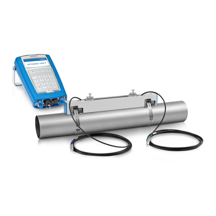
KROHNE OPTISONIC 6300 P Handbook
Portable ultrasonic clamp-on flowmeter for liquids
Hide thumbs
Also See for OPTISONIC 6300 P:
- Handbook (88 pages) ,
- Quick start (4 pages) ,
- Short manual (2 pages)

Related Manuals for KROHNE OPTISONIC 6300 P


Summary of Contents for KROHNE OPTISONIC 6300 P
- Page 1 OPTISONIC 6300 P Handbook Portable ultrasonic clamp-on flowmeter for liquids ER 2.1.x._ © KROHNE 02/2022 - 4000972605 - MA OPTISONIC 6300 P V2 R05 en...
- Page 2 All rights reserved. It is prohibited to reproduce this documentation, or any part thereof, without the prior written authorisation of KROHNE Messtechnik GmbH. Subject to change without notice. Copyright 2022 by KROHNE Messtechnik GmbH - Ludwig-Krohne-Str. 5 - 47058 Duisburg (Germany) www.krohne.com 02/2022 - 4000972605 - MA OPTISONIC 6300 P V2 R05 en...
-
Page 3: Table Of Contents
4.1 Installation for energy measurement ................39 4.2 Preparation of energy measurement................39 4.3 Mechanical installation ....................40 4.4 Program the converter for energy measurement ............42 4.5 Start measurement ......................42 02/2022 - 4000972605 - MA OPTISONIC 6300 P V2 R05 en www.krohne.com... - Page 4 7.2 Technical data......................... 66 7.3 Dimensions and weight ....................72 7.3.1 Clamp-on sensor ........................72 7.3.2 Converter..........................73 7.3.3 I/O box ........................... 74 7.3.4 Hardcase on wheels......................75 www.krohne.com 02/2022 - 4000972605 - MA OPTISONIC 6300 P V2 R05 en...
-
Page 5: Safety Instructions
In the table below, "_" is a place holder for possible multi-digit alphanumeric combinations, depending on the available version. INFORMATION! Compatibility and changes concerning communication interface and/or input and output connections are not applicable for the OPTISONIC 6300 P converter software. Release date Electronic Changes and... -
Page 6: Intended Use
KROHNE Clamp-on APP installed on a smart device. The OPTISONIC 6300 P is meant to be used temporarily for liquid flow and energy measurement. For example, the measured and calculated flow data is usable in process optimization, collecting additional process data, comparing flow data with existing flowmeters, verifying other flowmeters or flowmeter replacement during maintenance. -
Page 7: Certification
DANGER! The OPTISONIC 6300 P cannot be used in Hazardous Locations or Explosive Gas Atmospheres. 02/2022 - 4000972605 - MA OPTISONIC 6300 P V2 R05 en www.krohne.com... -
Page 8: Safety Instructions From The Manufacturer
The manufacturer reserves the right to alter the content of its documents, including this disclaimer in any way, at any time, for any reason, without prior notification, and will not be liable in any way for possible consequences of such changes. www.krohne.com 02/2022 - 4000972605 - MA OPTISONIC 6300 P V2 R05 en... -
Page 9: Product Liability And Warranty
This document is provided to help you establish operating conditions, which will permit safe and efficient use of this device. Special considerations and precautions are also described in the document, which appear in the form of icons as shown below. 02/2022 - 4000972605 - MA OPTISONIC 6300 P V2 R05 en www.krohne.com... -
Page 10: Warnings And Symbols Used
This symbol designates all instructions for actions to be carried out by the operator in the specified sequence. RESULT This symbol refers to all important consequences of the previous actions. www.krohne.com 02/2022 - 4000972605 - MA OPTISONIC 6300 P V2 R05 en... -
Page 11: Instruction For Transportation And Handling Of Batteries
• Do not expose contents of battery to water. • Dispose battery packs in accordance to WEEE regulations as described in section 6.5 or in accordance to additional local regulations. 02/2022 - 4000972605 - MA OPTISONIC 6300 P V2 R05 en www.krohne.com... -
Page 12: Device Description
7 Hard case INFORMATION! The delivered content can be different, depending on the version ordered. Refer to the included checklist to see if all items are delivered and present. www.krohne.com 02/2022 - 4000972605 - MA OPTISONIC 6300 P V2 R05 en... -
Page 13: Device Description
Product specific information and extensive product specification is available using PICK, the Product Information Center KROHNE web-tool. PICK can be found via the service menu button on the KROHNE.com website. Scan the auto ID code (data matrix) on the device nameplate to download all product specific information. -
Page 14: Nameplate (Example)
6 Additional info and warnings I/O Box nameplate information For detailed information of the I/O box nameplates (on the outside of the I/O box cover), refer to Mechanical installation on page 40 www.krohne.com 02/2022 - 4000972605 - MA OPTISONIC 6300 P V2 R05 en... -
Page 15: Installation For Flow Measurement
Excess of coupling grease can be removed from the sensor rail(s) and transducers with a dry • piece of cloth. Coupling grease on the converter housing can be removed using soapy water. 02/2022 - 4000972605 - MA OPTISONIC 6300 P V2 R05 en www.krohne.com... -
Page 16: Step 1: Find Location And Determine Data
• with a fixed reference point; refer to on page 30. Determine the transducer position with a paper roll • using a paper roll; refer to on page 32. www.krohne.com 02/2022 - 4000972605 - MA OPTISONIC 6300 P V2 R05 en... - Page 17 CAUTION! Make sure that the rail is not mounted at the highest point (risk for air bubbles) or at the lowest point (risk for particles) of the pipe. 02/2022 - 4000972605 - MA OPTISONIC 6300 P V2 R05 en www.krohne.com...
-
Page 18: Horizontal (Long) Pipes
1 path using bends in 2 dimensions: 20 DN; when having bends in 3 dimensions: 25 DN INFORMATION! 2 dimensional bends occur in a vertical or horizontal plane (X/Y) only, while 3 dimensional bends occur in both vertical and horizontal plane (X/Y/Z). www.krohne.com 02/2022 - 4000972605 - MA OPTISONIC 6300 P V2 R05 en... -
Page 19: T-Section
Install air vent downstream of the flow meter to prevent vacuum. Although this will not harm the meter, it may cause gases to come out of solution (cavitate) and interfere with proper measurements. Figure 3-6: Down going pipe 02/2022 - 4000972605 - MA OPTISONIC 6300 P V2 R05 en www.krohne.com... -
Page 20: Bends
Figure 3-8: Mounting on ascending or decending pipelines is possible INFORMATION! Vertical installation on a descending slope in the pipeline is only recommended when the back- pressure is controlled. www.krohne.com 02/2022 - 4000972605 - MA OPTISONIC 6300 P V2 R05 en... -
Page 21: Position Of Control Valve
A clamp-on flowmeter can be installed in the suction line of a pump if there is no cavitation in the pipeline system. 02/2022 - 4000972605 - MA OPTISONIC 6300 P V2 R05 en www.krohne.com... -
Page 22: Start Up Ufc 300 P Signal Converter
In case Bluetooth operation is not used, you can choose for the wired USB connection. Connect the I/O cable with USB to the Android mobile or tablet to maintain communication www.krohne.com 02/2022 - 4000972605 - MA OPTISONIC 6300 P V2 R05 en... - Page 23 DN200...750/ 8...30" Medium 1 MHz, 2 rails DN400...1500/ 16...60" Medium 1 MHz, 2 rails DN200...2000/ 8...80" Large 500 kHz, 2 rails DN200...4000/ 8...160" Large 500 kHz, 2 rails 02/2022 - 4000972605 - MA OPTISONIC 6300 P V2 R05 en www.krohne.com...
- Page 24 Number of rails needed < 190 190 INFORMATION! The maximum distance that can be covered with 1 rail is 195 mm. The minimum distance for two rails is 180 mm. www.krohne.com 02/2022 - 4000972605 - MA OPTISONIC 6300 P V2 R05 en...
-
Page 25: Step 3: Mount The Sensor Rails
Installation with metal straps (DN15...250) Put the metal straps around the pipe. Put the sensor rail(s) on the pipe including the transducers with fixed cables. 02/2022 - 4000972605 - MA OPTISONIC 6300 P V2 R05 en www.krohne.com... - Page 26 5 Pull the straps tight. 6 Use an allan key nr 5 (or a big screwdriver) to fixate the rails. Detail 7 of the metal strap fixed in connector. www.krohne.com 02/2022 - 4000972605 - MA OPTISONIC 6300 P V2 R05 en...
- Page 27 4 Fix the strap, as indicated below. 1 Push lever to create a opening. 2 Insert the nylon strap as indicated. 3 Release lever. 4 Pull strap tight. 02/2022 - 4000972605 - MA OPTISONIC 6300 P V2 R05 en www.krohne.com...
-
Page 28: Install 2 Or 4 Traverses With 1 Rail
• Unlock the transducer by turning the locking knob 2 counter clockwise. • Slide the transducer 1 to the new position 3. • Lock the transducer by turning the locking knob 2 clockwise. www.krohne.com 02/2022 - 4000972605 - MA OPTISONIC 6300 P V2 R05 en... -
Page 29: Install 2 Traverses With 2 Rails
• The advised distance 1 is defined from the center of the left transducer to the center side of the right transducer. Put the second transducer at position Z = advised distance 1 + X - distance 2 - 415 mm / 16.3". 02/2022 - 4000972605 - MA OPTISONIC 6300 P V2 R05 en www.krohne.com... -
Page 30: Install 1 Traverse With 2 Rails (Dn400
• Draw a line between the two markings. • Mount the DOWN rail in such a way that the transducer is at the marked location. Figure: Marking on pipeline www.krohne.com 02/2022 - 4000972605 - MA OPTISONIC 6300 P V2 R05 en... - Page 31 2 Add the advised distance to determine the position of the second transducer. Figure 3-16: Mounting second rail in Z mode (1 traverse) without using a reference point 1 Advised distance 1 = 2 + 3 02/2022 - 4000972605 - MA OPTISONIC 6300 P V2 R05 en www.krohne.com...
-
Page 32: Determine The Transducer Position With A Paper Roll
• Fold the paper exactly in half 1 • Put the folded paper back and fit it tightly on the pipe 2 Figure 3-18: Fold paper and place back on pipe line www.krohne.com 02/2022 - 4000972605 - MA OPTISONIC 6300 P V2 R05 en... - Page 33 Mark C is the perpendicular line with respect to the lines A and B. • After marking the lines: Determine with horizontal lines A/B and vertical line C the position of the sensor rails and transducers and place them accordingly. 02/2022 - 4000972605 - MA OPTISONIC 6300 P V2 R05 en www.krohne.com...
-
Page 34: Installing Rail With Magnetic Fixation Units
OPTISONIC 6300 P 3.4.5 Installing rail with magnetic fixation units Optionally, magnetic fixation units are used to install the OPTISONIC 6300 P sensor rail on a (Ferro metallic) pipeline surface. The initial fixation units can easily be demounted from the rail and replaced by the magnetic fixation units. -
Page 35: Apply Coupling Grease
Push the buttons of the fixing units to unlock and tilt the rail. Then put some coupling grease on the transducers and put the rail back by clicking. Figure 3-21: Greasing transducers 02/2022 - 4000972605 - MA OPTISONIC 6300 P V2 R05 en www.krohne.com... -
Page 36: Connect The Sensor Cable
Check settings in menu, change transducer distance until there is at least a low signal. • Continue the configuration in the mobile application and follow the advised settings and actions. www.krohne.com 02/2022 - 4000972605 - MA OPTISONIC 6300 P V2 R05 en... -
Page 37: Error Messages
> max 1 max volume flow exceeded check parameter in settings for pipe 1 flow > max 2 max volume flow exceeded check parameter in settings for pipe 2 02/2022 - 4000972605 - MA OPTISONIC 6300 P V2 R05 en www.krohne.com... - Page 38 DSP and microprocessor software 1 (bold) www.krohne.com 02/2022 - 4000972605 - MA OPTISONIC 6300 P V2 R05 en...
-
Page 39: Energy Measurement
Optionally, clamp-on PT 100 temperature sensors can be delivered, with a temperature range of 0...120°C / 32...248°F, including two meter cable and suitable for pipes up to DN300. 02/2022 - 4000972605 - MA OPTISONIC 6300 P V2 R05 en www.krohne.com... -
Page 40: Mechanical Installation
• Connect the PT 100 sensor to the I/O box according to the sticker on the I/O box. Figure 4-3: Extended I/O box with 2 temperature transmitters included for PT 100 sensors. www.krohne.com 02/2022 - 4000972605 - MA OPTISONIC 6300 P V2 R05 en... - Page 41 Figure 4-5: I/O box 1 I/O connector on converter 2 Connector of I/O box 3 I/O box with screw terminals for 1 mm wiring 4 Screw terminal pins 1...15 02/2022 - 4000972605 - MA OPTISONIC 6300 P V2 R05 en www.krohne.com...
-
Page 42: Program The Converter For Energy Measurement
907 kg) of ice. 1 kilo calorie per second Amount of heat required to increase 1 kg of 4187 water with 1 degree Celsius. 1 therm Equal to 100000 BTU 105506000 www.krohne.com 02/2022 - 4000972605 - MA OPTISONIC 6300 P V2 R05 en... -
Page 43: Electrical Connections
The converter has an ESD protection of +3 kV and -3 kV contact discharge. Above +3 kV and -3 kV ESD contact discharge, it’s possible that the converter can switch down and power up again (forced reset). 02/2022 - 4000972605 - MA OPTISONIC 6300 P V2 R05 en www.krohne.com... -
Page 44: Convertor Connection Options
3 I/O connector (for I/O box or connection to a specified android device) 4 Signal cable connection channel B (right pair of connectors for path 2) The connection options are described in the following sections www.krohne.com 02/2022 - 4000972605 - MA OPTISONIC 6300 P V2 R05 en... -
Page 45: Power Supply
The product is externally evaluated for a maximum ambient temperature of 40°C (without derating) and 60°C (50% derating), a maximum altitude of 3000 meters and at an overvoltage category II environment. Figure 5-1: 1 Connection 12 VDC power supply input 02/2022 - 4000972605 - MA OPTISONIC 6300 P V2 R05 en www.krohne.com... - Page 46 • Connect the cable with the 12 VDC car accessory plug to the power input of the flow converter. • Connect the car accessory plug into the 12 VDC socket of the car. www.krohne.com 02/2022 - 4000972605 - MA OPTISONIC 6300 P V2 R05 en...
-
Page 47: Front Panel Led Indications
Converter is connected to mains (automatically switch on function when connected to mains) • Converter is switched on in battery mode by pressing the ON/OFF button for 3 seconds 02/2022 - 4000972605 - MA OPTISONIC 6300 P V2 R05 en www.krohne.com... -
Page 48: Connection Of The Signal Cables
The flow converter can measure two paths (A and B) simultaneously. Use the left pair of connectors 1 and 2 for path A and the right pair connectors 1 and 2 for path B www.krohne.com 02/2022 - 4000972605 - MA OPTISONIC 6300 P V2 R05 en... -
Page 49: I/O Cable
Current input B+ Current input B- Not connected Temperature sensor 2 (PT 100, 4 wire connection) Not connected Not connected Not connected Table 5-1: Terminals of I/O box 02/2022 - 4000972605 - MA OPTISONIC 6300 P V2 R05 en www.krohne.com... -
Page 50: Connection Diagrams
At frequencies above 100 Hz, shielded cables must be used to connect the counters. Internal resistance of the counter Button, NO contact or similar Table 5-2: Description of symbols www.krohne.com 02/2022 - 4000972605 - MA OPTISONIC 6300 P V2 R05 en... - Page 51 32 VDC • U • I 22 mA 1.8 V • U (U • R ) / I Figure 5-5: Current output passive I 02/2022 - 4000972605 - MA OPTISONIC 6300 P V2 R05 en www.krohne.com...
- Page 52 ) / I L, min • Can also be set as a status output; for the electrical connection, see status output connection diagram. Figure 5-6: Pulse frequency output passive P www.krohne.com 02/2022 - 4000972605 - MA OPTISONIC 6300 P V2 R05 en...
- Page 53 L, max • The minimum load resistance R is calculated as follows: L, min = (U ) / I L, min Figure 5-7: Pulse frequency output active P 02/2022 - 4000972605 - MA OPTISONIC 6300 P V2 R05 en www.krohne.com...
- Page 54 • X designates the connection terminals A or B, depending on the version of the signal converter. Figure 5-9: Current input active IIn 1 Signal 2 2-wire transmitter (e.g. temperature) www.krohne.com 02/2022 - 4000972605 - MA OPTISONIC 6300 P V2 R05 en...
-
Page 55: Service
• such dangerous substances, to enclose a certificate with the device confirming that it is safe to handle and stating the • product used. 02/2022 - 4000972605 - MA OPTISONIC 6300 P V2 R05 en www.krohne.com... -
Page 56: Form (For Copying) To Accompany A Returned Device
The user must dispose of the WEEE to a designated collection point for the recycling of WEEE or send them back to our local organisation or authorised representative. www.krohne.com 02/2022 - 4000972605 - MA OPTISONIC 6300 P V2 R05 en... -
Page 57: Disassembly And Recycling
Torx screwdriver set Pozidriv screwdriver set • Adjustable wrench or wrench set (e.g. 10-27 mm) • There are no special guidance or actions necessary to disassemble the device. 02/2022 - 4000972605 - MA OPTISONIC 6300 P V2 R05 en www.krohne.com... -
Page 58: Disassembling The Optisonic 6000 Sensor Rail
• Remove the transducer/sensor(s) and plastic parts of the position knobs. • Remove the connection cables with the transducers. The rail is dismounted and separated now in aluminium / plastic parts and can be recycled further. www.krohne.com 02/2022 - 4000972605 - MA OPTISONIC 6300 P V2 R05 en... - Page 59 / PCB Standard cable RGD-316: PTFE 0.21 approx. 2 x 3 m/9 ft plastics/silver plated standard cable copper/ mixture 16 gram / 0.56 ounce copper per m/ft 02/2022 - 4000972605 - MA OPTISONIC 6300 P V2 R05 en www.krohne.com...
-
Page 60: Disassembling The Converter
7 gram / 0.25 ounce copper per m/ft Cable (I/O) box and power supply (adapter) Disposal No further disassembling necessary, dispose the components as described refer to page 56 . www.krohne.com 02/2022 - 4000972605 - MA OPTISONIC 6300 P V2 R05 en... - Page 61 • remove the metal screws that secure the LC display • open (using a small screwdriver) the plug that secures the cable from the LC display and then remove the LC display (V1 version only) 02/2022 - 4000972605 - MA OPTISONIC 6300 P V2 R05 en www.krohne.com...
- Page 62 8 Connector plate INFORMATION! The V1 (previous design) and V2 version have some different components. The illustration shows an abstract version and can deviate from the actual device version. www.krohne.com 02/2022 - 4000972605 - MA OPTISONIC 6300 P V2 R05 en...
-
Page 63: Overview Of The Converter Materials And Components
Silicon / rubber / 0.06 0.13 Seal-rings Neoprene PVC & connector 0.013 0.03 e.g. caps and foils (display) parts Table 6-2: Signal converter UFC 300 P 02/2022 - 4000972605 - MA OPTISONIC 6300 P V2 R05 en www.krohne.com... - Page 64 0.23 V1 version only Cabling 0.15* 0.3* * all cables are detachable from the device Ferrite negligible Copper, brass negligible Table 6-3: Signal converter UFC 300 P www.krohne.com 02/2022 - 4000972605 - MA OPTISONIC 6300 P V2 R05 en...
-
Page 65: Technical Data
Figure 7-1: Measuring principle (example reflected path set-up) 1 Transducer A 2 Transducer B 3 Flow velocity 4 Transit time from transducer A to B 5 Transit time from transducer B to A 02/2022 - 4000972605 - MA OPTISONIC 6300 P V2 R05 en www.krohne.com... -
Page 66: Technical Data
1 x host port (Mobile device USB-C via I/O connection of OPTISONIC 6300 P to make a connection with Android device). Self diagnostics Integrated verification, diagnostic functions: flowmeter, process, measured value, empty pipe detection, bar graph. www.krohne.com 02/2022 - 4000972605 - MA OPTISONIC 6300 P V2 R05 en... - Page 67 < ± 3% of the actual measured flow rate; for 0.5…20 m/s / 1.64…65.6 ft/s < ± 15 mm/s / 0.6 inch/s for 0.1…0.5 m/s / 0.33…1.64 ft/s Repeatability < ± 0.2% 02/2022 - 4000972605 - MA OPTISONIC 6300 P V2 R05 en www.krohne.com...
- Page 68 Sensor Anodized aluminium (rail) Converter Polyamide PA12, covered with TPE soft touch layer on the sides Hard case Polypropylene, inner material EPP Soft case Polyester, inner material EPP www.krohne.com 02/2022 - 4000972605 - MA OPTISONIC 6300 P V2 R05 en...
- Page 69 I 22 mA 1 k 32 VDC Passive I 22 mA 1.8 V at I = 22 mA (U ) / I 02/2022 - 4000972605 - MA OPTISONIC 6300 P V2 R05 en www.krohne.com...
- Page 70 = 1.5 V at I 1 mA 0, max = 2.5 V at I 10 mA 0, max = 5.0 V at I 20 mA 0, max www.krohne.com 02/2022 - 4000972605 - MA OPTISONIC 6300 P V2 R05 en...
- Page 71 Hardcase on wheels: IP67 Power adaptor: IP40, NEMA 1 Shock resistance IEC 60068-2-27 30 g for 18 ms Vibration resistance IEC 60068-2-64 1 g up to 2000 Hz 02/2022 - 4000972605 - MA OPTISONIC 6300 P V2 R05 en www.krohne.com...
-
Page 72: Dimensions And Weight
81.5 42.7 1 with transducers / cable, without mounting strap Version Dimensions [inches] Approx. weight [lb] 16.0 1.54 16.0 1.68 1 with transducers / cable, without mounting strap www.krohne.com 02/2022 - 4000972605 - MA OPTISONIC 6300 P V2 R05 en... -
Page 73: Converter
TECHNICAL DATA OPTISONIC 6300 P 7.3.2 Converter Dimensions UFC 300 P converter Dimensions [mm] Approx. weight [kg] Dimensions [inch] Approx. weight [lb] 11.4 02/2022 - 4000972605 - MA OPTISONIC 6300 P V2 R05 en www.krohne.com... -
Page 74: I/O Box
TECHNICAL DATA OPTISONIC 6300 P 7.3.3 I/O box Dimensions I/O box Dimensions [mm] Approx. weight [kg] 112.5 84.6 0.34 Dimensions [inch] Approx. weight [lb] 0.75 www.krohne.com 02/2022 - 4000972605 - MA OPTISONIC 6300 P V2 R05 en... -
Page 75: Hardcase On Wheels
Dimensions hardcase on wheels Dimensions [mm] Approx. weight [kg] Dimensions [inch] Approx. weight [lb] 20.5 15.5 14.1 Dimensions softcase Dimensions [mm] Approx. weight [kg] Dimensions [inch] Approx. weight [lb] 20.9 15.8 02/2022 - 4000972605 - MA OPTISONIC 6300 P V2 R05 en www.krohne.com... - Page 76 Engineering, commissioning, calibration, maintenance and training services Head Office KROHNE Messtechnik GmbH Ludwig-Krohne-Str. 5 47058 Duisburg (Germany) Tel.: +49 203 301 0 Fax: +49 203 301 10389 info@krohne.de The current list of all KROHNE contacts and addresses can be found at: www.krohne.com...
Need help?
Do you have a question about the OPTISONIC 6300 P and is the answer not in the manual?
Questions and answers