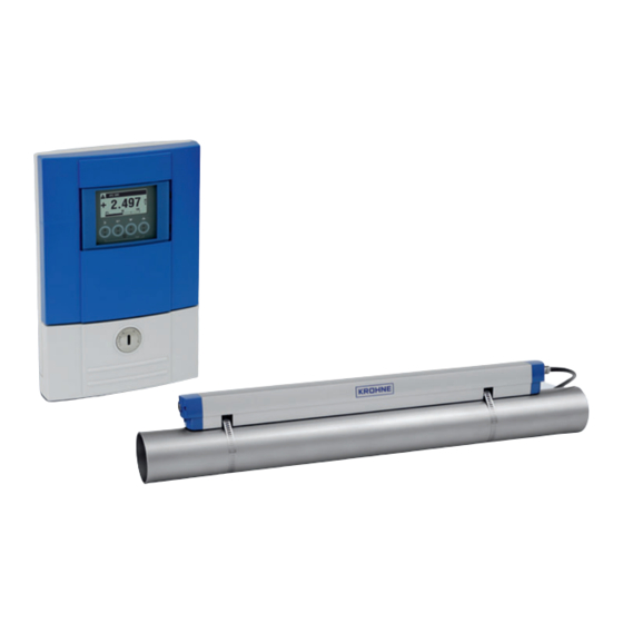
KROHNE OPTISONIC 6300 Quick Start Manual
Ultrasonic clamp-on flowmeter
Hide thumbs
Also See for OPTISONIC 6300:
- Handbook (212 pages) ,
- Manual (60 pages) ,
- Quick start manual (56 pages)
Table of Contents
Advertisement
Advertisement
Table of Contents

Related Manuals for KROHNE OPTISONIC 6300


Summary of Contents for KROHNE OPTISONIC 6300
- Page 1 OPTISONIC 6300 Quick Start Ultrasonic Clamp-on Flowmeter...
- Page 2 CD-ROM and enclose it with the device. Unless this form is completely filled out, it will unfortunately not be possible for KROHNE to perform repair or inspection. Respect general and local electrical safety requirements.
-
Page 3: Scope Of Delivery
OPTISONIC 6300 Scope of delivery UFC 300 Altometer, Dordrecht NL - 3313 LC Ta= -40 ... +70 C OPTISONIC 6000 IP66/67 according to EN 60529 S/N: A06 xxxxx Manufactured: 2006 Tm: -40 ... +120 C Calibration nr.: xxxxxxxxx Altometer, Dordrecht NL - 3313 LC Ta= -40 ... - Page 4 OPTISONIC 6300 Additionally for large version: Altometer, Dordrecht NL - 3313 LC Ta= -40 ... +70 C OPTISONIC 6000 IP66/67 according to EN 60529 S/N: A06 xxxxx Altometer, Dordrecht Manufactured: 2006 NL - 3313 LC Ta= -40 ... +70 C Tm: -40 ...
- Page 5 OPTISONIC 6300 Visual check Altometer, Dordrecht NL - 3313 LC Ta= -40 ... +70 C OPTISONIC 6000 IP66/67 according to EN 60529 S/N: A06 xxxxx Manufactured: 2006 Tm: -40 ... +120 C Calibration nr.: xxxxxxxxx Altometer, Dordrecht NL - 3313 LC...
- Page 6 OPTISONIC 6300 Inlet, outlet and recommended mounting area Min. 10 DN Min. 5 DN OK, 120° 7.30959.22.00...
- Page 7 OPTISONIC 6300 General mechanical installation NOTE! This chapter explains the basic handlings that are used throughout this Quick Start. Do not execute them at first reading! Installation of the rails with the metal straps Installation of the rails with the metal straps...
- Page 8 OPTISONIC 6300 • 7: Repeat steps 1...6 at the other side of the rail. Change the position of the transducer Change the position of the transducer Change the position of the transducer Change the position of the transducer • Unlock the floating transducer...
- Page 9 OPTISONIC 6300 • Lock the transducer by turning the locking knob clockwise. Greasing the transducer surfaces Greasing the transducer surfaces Greasing the transducer surfaces Greasing the transducer surfaces www.krohne.com...
- Page 10 OPTISONIC 6300 Mounting the cover Mounting the cover Mounting the cover Mounting the cover 7.30959.22.00...
- Page 11 OPTISONIC 6300 General instructions for programming Human machine interface (HMI) Human machine interface (HMI) Human machine interface (HMI) Human machine interface (HMI) Product name X shows optical button is activated Indication of menu number Block indicates the menu level 0...100%...
- Page 12 OPTISONIC 6300 Description Used symbol start installation, select > menu return down escape > + Start installation menu Start installation menu Start installation menu Start installation menu • Connect converter to power supply and power up converter. First and second page appear intermittently...
- Page 13 OPTISONIC 6300 • Keep left button ">" pressed, until in display appears "release key now" www.krohne.com...
- Page 14 OPTISONIC 6300 Installation menu Installation menu Installation menu Installation menu • > X1...X7 language > select from list using > GDC IR interface > activate / cancel X3.1, X3.2, … units > X3.1 size > select from list using >...
- Page 15 OPTISONIC 6300 X6.8 VoS liner material > read advise or fill in using > X6.9 liner thickness > fill in using > X6.10 fluid > select from list using > X6.11 VoS fluid > read advise or fill in using >...
- Page 16 OPTISONIC 6300 X9...X10 install transd. 1 > X9.1, X9.2,… X9.1 transducer set > read preset Ta,Tb,Tc / confirm or overrule using > X9.2 calibration number read X9.3 number of > read preset 1,2,4 / traverses confirm or overrule using >...
- Page 17 OPTISONIC 6300 submenus identical to X9.1 up to X9.12 www.krohne.com...
- Page 18 OPTISONIC 6300 Instrument versions The OPTISONIC 6300 Flowmeter is available for three diameter ranges as small, medium and large version. The procedure to install a large version differs from the procedure for a small and medium version. Rail, small version Rail, medium version Choose for V-mode or ...
- Page 19 OPTISONIC 6300 DOWN 150mm X.1 ... X.9.8.4 X.9.8.5 DOWN DOWN Enter the values for the installation menu, X1...X9.8.4 Read the advised mounting distance in menu X9.8.5 Choose for Z-mode (default) or ... Choose for V-mode Finish the installation menu NOTE! For the large version, proceed with the chapter "instructions for...
- Page 20 OPTISONIC 6300 Installation instructions for small and medium version Small version: single pipe / single path Medium version: single pipe / single path Small version: single pipe / dual path Medium version: single pipe / dual path Small version: dual pipe / single path Medium version: dual pipe / single path 7.30959.22.00...
- Page 21 OPTISONIC 6300 Rail version Rail version Rail version Rail version Diameter range Diameter range Diameter range Diameter range Preferred measuring modes Preferred measuring modes Preferred measuring modes Preferred measuring modes Small DN15...100 / 0.5...4" < DN25: W-mode (4 traverses) DN25: V-mode (2 traverses) Medium DN50...400 / 2...16"...
- Page 22 OPTISONIC 6300 Connect blue cable to 1U (to 2U for 2 sensor) and the green cable to 1D (2D for 2 sensor) Communication I/O Power supply: 24 VAC/DC or 100...240 VAC 7.30959.22.00...
- Page 23 OPTISONIC 6300 Cover, electronics compartment Cover, terminal compartment for power supply and inputs/outputs Cover, sensor terminal compartment Cable entry for power Cable entry for inputs/outputs Cable entry for sensor cable • Power up the converter (do not mount and/or connect the rails yet) •...
- Page 24 OPTISONIC 6300 • X9.6: Read the actual signal strength CAUTION! Advice on signal strength: Advice on signal strength: Advice on signal strength: Advice on signal strength: Signal > 75%: good signal, optimization loop not needed Signal > 75%: Signal > 75%: Signal >...
- Page 25 OPTISONIC 6300 • X9.10: Path ready? If you enter "No" then the installation is not saved. If you enter "Yes" the installation can be saved in X9.11. If you have: 1 path or pipe: you are finished, proceed with X9.11...
- Page 26 OPTISONIC 6300 Installation instructions for large version NOTE! You need a calculator, measuring band and pen & paper to install a large version Altometer, Dordrecht NL - 3313 LC Ta= -40 ... +70 C OPTISONIC 6000 IP66/67 according to EN 60529...
- Page 27 OPTISONIC 6300 3313 LC, Dordrecht The Netherlands Ta= -40 ... +70 C OPTISONIC 6000 SMALL IP66/67 according to EN 60529 XXXX Manufactured: 2006 Tm: -40 ... +120 C NOTE! Default measuring mode is the Z-mode. This will work in most cases.
- Page 28 OPTISONIC 6300 • Power up the converter (do not mount and/or connect the rails yet) • Fill in menu X1...X7 as described in section "Installation menu" in chapter "General instructions for programming". Select "1 path" initially in X5 • X9.1: Check the reading with the sensor code (Ta/Tb) on rail •...
- Page 29 OPTISONIC 6300 Mounting the UP rail Mounting the UP rail Mounting the UP rail Mounting the UP rail CAUTION! Make sure that you mount the rail parallel to the pipe. Mount the fixing units and the cable box as shown below Align the UP rail with the pipeline.
- Page 30 OPTISONIC 6300 • Pull the metal strap through the upper slit of the UP rail 1. • Take the metal strap around the pipe (45...60°) 2. • Push the end of the metal strap in the lower slit of the fixing unit 3.
- Page 31 OPTISONIC 6300 • Push the metal strap through the upper slit of the fixing unit 6. • Pull the metal strap moderately tight by hand 7. CAUTION! Choose between Z and V mode before you proceed. The Advised Distance (menu X9.4) must be > 246 mm / 9,7" for V-mode.
- Page 32 OPTISONIC 6300 Mounting the DOWN rail for Z-mode Mounting the DOWN rail for Z-mode Mounting the DOWN rail for Z-mode Mounting the DOWN rail for Z-mode Measure the outer diameter of the pipe with a measuring band. For Z-mode, you must install the DOWN rail at the opposite location at the pipe.
- Page 33 OPTISONIC 6300 Measure the distance between the transducer of the UP rail and the reference point. Add the Advised Distance and mark the location on the alignment line. • Mount the DOWN rail in such a way that the transducer is at the marked location 2.
- Page 34 OPTISONIC 6300 Mark the cables at a distance of 1.63 x outer diameter. Outer diameter of pipeline INFORMATION! For large diameters you can use the weight of the metal plates to throw the cable around the pipe. First release one of the cables in...
- Page 35 OPTISONIC 6300 Altometer, Dordrecht NL - 3313 LC Ta= -40 ... +70 C OPTISONIC 6000 IP66/67 according to EN 60529 S/N: A06 xxxxx Manufactured: 2006 Tm: -40 ... +120 C Calibration nr.: xxxxxxxxx • Calculate the middle of the alignment line between the 4 V-marks as shown.
- Page 36 OPTISONIC 6300 • Grease all transducers, see "General mechanical installation" NOTE! It can be necessary to install the DOWN rail as shown below. DOWN 7.30959.22.00...
- Page 37 OPTISONIC 6300 Mounting the DOWN rail in V-mode Mounting the DOWN rail in V-mode Mounting the DOWN rail in V-mode Mounting the DOWN rail in V-mode For V-mode, you must install the DOWN rail in line with the UP rail. It is easier to install than the Z-mode, but you need more free pipe length.
- Page 38 OPTISONIC 6300 Electrical connections Electrical connections Electrical connections Electrical connections Connect the blue cable to the UP rail. Connect the green cable to the DOWN rail. Make connections in cable box. Cable to converter Turn the screws clockwise to secure the caps.
- Page 39 OPTISONIC 6300 Connect blue cable to 1U (to 2U for 2 sensor) and the green cable to 1D (2D for 2 sensor) Communication I/O Power supply: 24 VAC/DC or 100...240 VAC www.krohne.com...
- Page 40 OPTISONIC 6300 Cover, electronics compartment Cover, terminal compartment for power supply and inputs/outputs Cover, sensor terminal compartment Cable entry for power Cable entry for inputs/outputs Cable entry for sensor cable NOTE! See also the section "Installation menu" in chapter "General instructions for programming".
- Page 41 OPTISONIC 6300 • X9.6: Check signal CAUTION! Advice on signal strength: Advice on signal strength: Advice on signal strength: Advice on signal strength: Signal > 75%: good signal, optimization loop not needed Signal > 75%: Signal > 75%: Signal > 75%: Signal 50...75%: fairly good signal, optimization loop can improve...
- Page 42 OPTISONIC 6300 • X9.10: Path ready? If you enter "No" then the installation is not saved. If you enter "Yes" the installation can be saved in X9.11. If you have: 1 path or pipe: you are finished, proceed with X9.11...
- Page 43 OPTISONIC 6300 www.krohne.com...
- Page 44 OPTISONIC 6300 Contact KROHNE Altometer KROHNE Altometer KROHNE Altometer KROHNE Altometer Kerkeplaat 12 3313 LC Dordrecht Postbus 110 3300 AC Dordrecht, the Netherlands www.krohne.com 7.30959.22.00...
Need help?
Do you have a question about the OPTISONIC 6300 and is the answer not in the manual?
Questions and answers