
Related Manuals for Extron electronics NetPA 502 AT


Summary of Contents for Extron electronics NetPA 502 AT
- Page 1 User Guide PRELIMINARY Audio Power Amplifiers NetPA AT Series NetPA 502 AT and NetPA 1001-70V AT Networked Audio Power Amplifiers with Dante™ 68-2649-01 Rev. Ax3 05 15...
-
Page 2: Safety Instructions
Safety Instructions Safety Instructions • English Инструкция по технике безопасности • Русский WARNING: This symbol, , when used on the product, is intended to ПРЕДУПРЕЖДЕНИЕ: Данный символ, , если указан alert the user of the presence of uninsulated dangerous voltage within the на... - Page 3 FCC Class B Notice NOTE: This device complies with part 15 of the FCC rules. Operation is subject to the following two conditions: (1) This device may not cause harmful interference, and (2) This device must accept any interference received, including interference that may cause undesired operation.
-
Page 4: Conventions Used In This Guide
, and trademarks are the property of (SM) (TM) RGB Systems, Inc. or Extron Electronics: Registered Trademarks (®) AVTrac, Cable Cubby, CrossPoint, eBUS, EDID Manager, EDID Minder, Extron, Flat Field, GlobalViewer, Hideaway, Inline, IP Intercom, IP Link, Key Minder, LockIt, MediaLink, PlenumVault, PoleVault, PowerCage, Pure3, Quantum, SoundField, SpeedMount, SpeedSwitch, System INTEGRATOR, TeamWork,... -
Page 6: Table Of Contents
Contents Introduction Dante Configuration and Operation ........... 1 ..13 About this Guide ..........1 NetPA AT Bus ........... 13 Overview ............1 Managing Network Traffic ......... 13 Features ............. 2 Creating a Physical Dante Network ....14 Application Example ........... 4 Starting Dante Controller ........ -
Page 7: Introduction
The NetPA 502 AT two channel amplifier delivers 50 watts rms per channel into 4 ohms or 25 watts rms per channel into 8 ohms. The NetPA 502 AT is ideal for amplification of voice or program content to stereo speakers, or two sets of 8 ohm ceiling speakers in a dual zone application. -
Page 8: Features
Extron DMP 128 AT, to an input on a NetPA amplifier. The NetPA 502 AT and NetPA 1001-70V AT can output incoming Dante channels as line level signals to simultaneously feed the audio into another speaker zone or audio system. - Page 9 faults to prevent damage to the amplifier and speakers. • Remote standby port — Enables the NetPA AT to be remotely powered down when not in use, reducing operating cost. • High pass filter for high impedance model — This switch selectable filter, available on the 70 volt model, rolls off frequencies below 80 Hz to prevent saturation of speaker transformers.
-
Page 10: Application Example
Application Example The illustration below is one example of configuring a system using the NetPA AT. Figure 1. Application Example NetPA AT Series User Guide • Introduction... -
Page 11: Hardware Installation
Hardware Installation This section describes the front and rear panel features and the rear panel connections and includes the following topics: • Mounting the NetPA AT • Hardware Configuration • Rear Panel Features and Connections • Front Panel Indicators May result in serious injury. Installation and service must be WARNING: performed by authorized personnel only. -
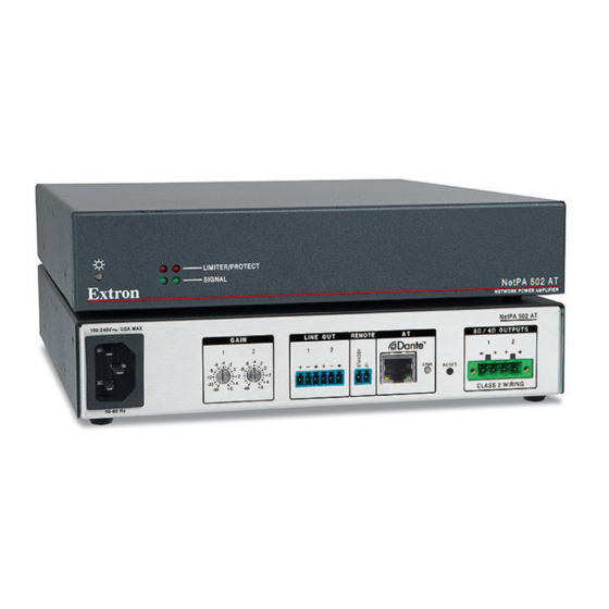
Page 12: Rear Panel Features And Connections
RJ-45 Ethernet connector HPF (high pass filter switch) Figure 2. NetPA 502 AT and NetPA 1001-70V Rear Panels Power — Be sure that power to the NetPA AT is turned off first by disconnecting the power. NOTE: Adjust the audio level to = (full attenuation) prior to powering the amplifier... - Page 13 Line out connection — Connect an amplifier or other device to the 3-pole, 3.5 mm captive screw connectors for channel 1 and channel 2 (NetPA 502 AT) or the single channel (NetPA 1001-70V). Wire as shown below. Audio Output Wiring...
- Page 14 Amplified stereo audio output connection — Wire the speakers to the output connector of the NetPA 502 AT using the 4-pole captive screw connector, as shown below. / 4 Ω Do not tin the wires! 8 Ω Amplified mono audio output connection — Wire the speakers to the output connector of the NetPA 1001-70V AT using the 2-pole captive screw connector, as shown below.
-
Page 15: Front Panel Indicators
NetPA 502 AT NETWORK POWER AMPLIFIER LIMITER/PROTECT SIGNAL NetPA 1001-70V AT NETWORK POWER AMPLIFIER Figure 3. NetPA 502 AT and NetPA 1001-70V AT Front Panels Power LED — Lights solid green when powered on and active. • Lights amber when: •... -
Page 16: Software Installation
Software Installation This section describes the software requirements and installation and includes the following topics: • NetPA AT Software • Software Installation Overview • Software Download and Installation NetPA AT Software The NetPA AT has both hardware and software controls. Software configuration and operation are accomplished using a PC running Microsoft Windows 7 or newer. -
Page 17: Software Download And Installation
Dante Controller must be installed to route audio transmit and receive channels to the NetPA. Dante Controller for Windows From the Extron Electronics web page at www.extron.com, enter in the NetPA AT search field and press <Enter>.The NetPA AT product page opens. - Page 18 Figure 5. Download Center - Dante Download Fill in the required fields. Click Download Save the file to your desktop (or other known location). Locate and double-click the saved Dante Controller file to begin installation. Follow the onscreen instructions. When the installation completes, close the installation dialog.
-
Page 19: Dante Configuration And Operation
Dante Configuration and Operation This section describes the NetPA AT network installation, configuration, and control using the Dante Controller for Windows. • NetPA AT Bus • Managing Network Traffic • Creating a Physical Dante Network • Starting Dante Controller • Selecting Inputs and Outputs for Dante •... -
Page 20: Creating A Physical Dante Network
Star network topology places one DMP 128 C AT as the central unit, which connects directly to up to three more units. Alternatively, a larger network switch in place of the central DMP 128 AT, allows more than four NetPA ATs to connect in the star configuration. NetPA 502 AT NetP NetPA 50... -
Page 21: Starting Dante Controller
Starting Dante Controller To launch Dante Controller from the computer start menu, select: All Programs > Audinate > Dante Controller > Dante Controller screen opens. Dante Controller - Network View If the network has a DHCP server, it receives its IP configuration using the standard DHCP protocol. -
Page 22: Device Name
Device Name The default device name of the NetPA AT consists of its model name, followed by the last six digits of its MAC address (for example, NetPA 063f70 Multiple devices on the same network can present difficulty identifying inputs and outputs. To avoid confusion, rename each device to a unique identifier immediately after you connect it (see on page 19). - Page 23 The Dante Controller - Device View dialog opens. Select your device from the drop-down list. (Select a Dante Device...) NOTES: • If there are multiple NetPA ATs connected to the network that have not been renamed, to identify an individual device you must obtain the MAC address of the desired device from the label on the rear panel.
- Page 24 Click to enter the new name, then close the Device Configuration dialog. The new name is written to the NetPA AT. Repeat as necessary for all NetPA AT devices. NOTE: After the NetPA AT is renamed, it can remain connected to the network. However, subsequent devices must be connected one at a time and renamed before the next device is connected.
-
Page 25: Renaming An Input
Renaming an Input If the devices are not properly named, Dante network connection points can quickly become unmanageable in large systems. To better organize the various inputs, it is recommended you name each input using descriptions of the device they belong to, the location of the device, or the purpose of the input. - Page 26 To rename an input From the menu on the screen, select Device Network View Device View. Alternatively, press <Ctrl+D> on the keyboard. From the drop-down menu, select the name of your NetPA AT. Select a Dante Device Figure 10. Device Drop-down Menu on the Device View Screen Select the tab (see figure 11, Receive...
-
Page 27: Selecting Inputs And Outputs For Dante
Selecting Inputs and Outputs for Dante Dante Controller is used for all network level signal routing of AT bus inputs and outputs. The digital input channels of the NetPA AT are shown in Dante Controller as receivers. The digital inputs are available in Dante Controller for routing to other Dante devices. Routing Signals using Dante Channels received from the network are routed using the Dante Controller Network View... -
Page 28: Dante Operation
Indicates a pending connection. Indicates a broken connection (subscription). Indicates the transmitting device has been removed from the network or is switched off. See the Dante Controller User Guide, available at the Audinate website, for additional information. NOTE: After making changes to Dante network routing such as connections (subscriptions), device names, or channel labels, wait at least 5 seconds before disconnecting or powering down the devices. - Page 29 Ensure the control computer and NetPA AT are connected to the same network. From the start menu select All Programs > Audinate > Dante Controller > Dante . The Dante Controller - Network View screen opens. Controller Dante Controller auto-discovers Dante devices on the network and advertises itself to allow other Dante-enabled devices to communicate with it.
-
Page 30: Route Inputs And Outputs
Route Inputs and Outputs Figure 14. Routing Inputs and Outputs Click the box next to the input channels (receivers) on the NetPA (NetPA- Classroom-01 in the example above). All device outputs (transmitters) display horizontally. Click the junction of the desired connection (Example: DMP128-LectureHall Output-01 to NetPA-Classroom-01 INPUT-MONO). -
Page 31: Identifying The Physical Device
Identifying the Physical Device If the amplifier needs to be physically identified, the identify device tool can be used to aid in its location. Start with steps 1 through 3 of Rename the NetPA AT on page To identify the NetPA, click on the “eye” icon. Both the front panel power LED (see figure 3... - Page 32 From the toolbar, select Device>Device View dialog box opens. Dante Controller - Device View ‘Select your device from the drop-down list. (Select a Dante Device...) Click the tab to open the network configuration page. Network Config Click on , then enter the IP address and the Manually configure an IP Address subnet mask.
-
Page 33: Dante Troubleshooting
Dante Troubleshooting The most common Dante troubleshooting issues occur when no devices are discovered by the Dante Controller software, or routing is not successful or is prevented. Both issues occur when software is not able to properly discover devices operating on the Dante network. Before moving into more difficult troubleshooting, shut down Dante Controller and reseat the Ethernet cable connecting the PC to the Dante network. - Page 34 Additional Troubleshooting For further help, see Dante Troubleshooting in the Dante help file. To access the Dante help file, do any of the following: • figure Click the icon in the upper-right corner of the Dante screen (see , in the Help following figure).
-
Page 35: Resetting The Netpa At
Resetting the NetPA AT The NetPA AT utilizes DHCP addressing by default. A recessed reset button on the rear panel (see figure 2 on page 6) initiates a reset mode. Reset will set the IP addressing mode to DHCP (Dante default), clear the previous IP address, and reset the device name to default. -
Page 36: Reference Information
Reference Information This section describes mounting options and the defeatable auto power-down timer. • Mounting of the NetPA AT • Defeatable Auto Power-down Timer Mounting of the NetPA AT The NetPA AT can be mounted in the following ways: • Set on a table, • Mounted on a rack shelf, •... -
Page 37: Rack Shelf Mounting
Rack Shelf Mounting For rack mounting, do not install the rubber feet. The NetPA AT can be mounted on a 19 inch Universal 1U or Basic rack shelf. To rack mount the NetPA AT on a rack shelf: If rubber feet are installed on the bottom of the NetPA AT, remove them. Mount the NetPA AT on the rack shelf, using two 4-40 x 3/16 inch screws in opposite (diagonal) corners to secure the unit to the shelf. -
Page 38: Under-Desk Mounting
Under-desk Mounting The table or wall mounting brackets extend approximately 1/4 inch (6.4 mm) above the top surface of the enclosure. This design allows for an air space between the enclosure and the surface to which it is mounted. Mount the NetPA AT under a desk or table as follows: Attach the MBU 125 brackets. -
Page 39: Defeatable Auto Power-Down Timer
Defeatable Auto Power-down Timer The auto power-down timer determines whether or not the NetPA AT enters standby mode. The amplifier powers down if the input signal remains below the input signal detection threshold for about 25 minutes. The timer resets whenever the input signal exceeds the input signal detection threshold. Resetting the timer starts a new 25-minute countdown until the amplifier powers down. - Page 40 The circuit board nearest the rear of the NetPA AT has a jumper to enable or disable the power-down timer. By default, the jumper is set to enable (the jumper set on the leftmost pins). Setting the jumper on the rightmost pins disables the power-down timer. ATTENTION: Do not touch the electronic components or the connectors on the backplane or on the circuit boards without being electrically grounded.
-
Page 41: Extron Warranty
Extron Electronics makes no further warranties either expressed or implied with respect to the product and its quality, performance, merchantability, or fitness for any particular use. In no event will Extron Electronics be liable for direct, indirect, or consequential damages resulting from any defect in this product even if Extron Electronics has been advised of such damage.
Need help?
Do you have a question about the NetPA 502 AT and is the answer not in the manual?
Questions and answers