Table of Contents

Subscribe to Our Youtube Channel
Related Manuals for TBK vision TBK-BUL4705EIR24


Summary of Contents for TBK vision TBK-BUL4705EIR24
-
Page 1: Operating Instructions
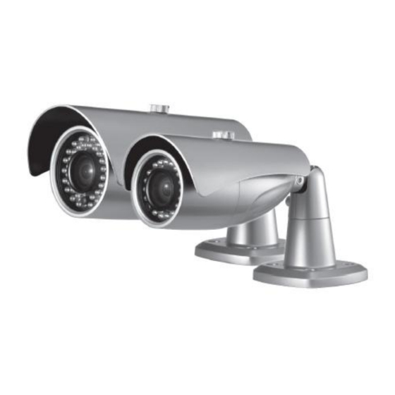
TBK-BUL4705EIR24 2DNR(Digital Noise Reduction) Day & Night IR-LED Vari-focal Bullet Camera OPERATING INSTRUCTIONS TBK-BUL4705EIR24 Before installing and using the camera, please read the instructions thoroughly and retain them for reference. - Page 2 Caution This symbol is intended to alert the user to the presence of non insulated “dangerous voltage” within the product‟s enclosure that may be of sufficient magnitude to constitute a risk of electric shock to persons. The exclamation point within an equilateral triangle is intended to alert the user to the presence of important operating and maintenance (servicing) instructions in the literature accompanying the product.
-
Page 3: Table Of Contents
Contents Composition ----------------------------------------------- 4 Explanation for Accessories --------------------------- 4 Features ---------------------------------------------------- 5 Dimension -------------------------------------------------- 6 Parts Name ------------------------------------------------- 7 Connections ------------------------------------------------- 8 Adjustments -------------------------------------------- 9~10 OSD Menu Instructions ---------------------------- 11~22 Specifications ----------------------------------------- 23 ~ 24... -
Page 4: Composition
Composition Confirm that the following parts are included: SUN SHIELD CAMERA SERVICE MONITOR CONTROL CABLE ACCESSORIES INSTRUCTION MANUAL Explanation for Accessories ▪ L-Wrench : Unscrew and tighten bracket screw for pan & tilt adjustment of camera. ▪ Screws : Firmly attach the bracket to the wall or ceiling. ▪... -
Page 5: Features
Features 1/3” Sony Super HAD Ⅱ High-resolution Color CCD 600TVL High-Resolution f=2.8~11mm Vari-Focal, DC Auto Iris F1.2 Day & Night Lens Built-in 2DNR, OSD function Back Light or High Light Compensation(BLC/HLC) function Auto switching IR-LED control by photocell - IR LED : 24pcs ... -
Page 6: Dimension
Dimension (Unit: mm) -
Page 7: Parts Name
Parts Name 1. Bolt 2. Sun-Shield 3. Front Case 4. Rear Case 5. Service Monitor Output Cap DC12V TYPE 6. Bracket VIDEO-OUT 7. Video / Power Cable POWER... -
Page 8: Connections
Connections ▪ Power connection - DC12V Type : Requires DC12V.(Polarity) ▪ All camera models are supplied with second video output on the camera model. To use this feature along with a service monitor, service monitor cable/connector is required. ▪ To set up OSD menu externally, service monitor and control cable is required. -
Page 9: Adjustments
Adjustments Vari-focal, DC Auto Iris Lens 1. Unscrew Front Case from the Rear Case. 2. Loosen Zoom &Focus screws and make necessary adjustment as shown. - Field of View : Telephoto(T) to Wide(W) - Focus : Near(N) to Infinity(∞) 3. If OSD menu set-up is necessary, refer to page 11 of this manual for further instructions. - Page 10 Adjusting Camera View PAN : Adjusting view directions TILT : Adjusting view angle ROTATION : Adjusting screen view ▪ Bracket(Cable Managed Bracket) Install the Mounting Bracket at the desired location. Using supplied screws fix a bracket to the wall. Adjusting pan, tilt or rotation with supplied wrench the camera angle.
-
Page 11: Osd Menu Instructions
OSD Menu Instructions 1. OSD Control Key (Service Monitor and Control Cable) ■ OSD Menu Control > SET Key: Access to the menu or confirm the setting. To enter the main menu, press the Set Key down once. > UP/DOWN key(▲▼): Choose the desired sub-menu. >... - Page 12 AWT2 AWT → SET AWT → SET(PUSH) MANUAL COLOR TEMP. MANUAL BLUE 0~255 0~255 RETURN RET / END COLOR TEMP. INDOOR − BLUE − RETURN RET / END COLOR TEMP. OUTDOOR − BLUE − RETURN RET / END EXPOSURE AREA SEL AREA1 / AREA2 AREA STATE ON / OFF...
- Page 13 MODE ALL DAY NIGHT ONLY RETURN RET / END IMAGE ADJ. LENS SHAD. ON / OFF 2DNR ON / OFF MIRROR ON / OFF FONT COLOR FRONT 0 ~ 15 ID & TITLE 0 ~ 15 RETURN RET / END CONTRAST 0 ~ 255 SHARPNESS...
- Page 14 SPECIAL CAM TITLE ON / OFF DAY & NIGHT AURO / COLOR / BW / EXT MOTION AREA SEL. AREA1 ~ AREA4 AREA STATE ON / OFF HEIGHT 0 ~15 WIDTH 0 ~15 LEFT / RIGHT 0 ~15 TOP / BOTTOM 0 ~15 DEGREE 0 ~ 255...
-
Page 15: Adjustments
EXIT OSD Menu Instructions 3. Menu Setup The Setup is used to control and adjust the many features and options available on your camera. Read thoroughly before making any adjustments. Note : These options have been pre-configured at the factory for optimal performance. Altering these settings are not recommended. - Page 16 OSD Menu Instructions > AUTO: Select the AUTO mode for automatic adjustment of the shutters. It will slow down or speed up depending on the environment. > FLK: Select the FLK mode if the screen flickers due to differences in light and electric frequencies.
- Page 17 OSD Menu Instructions ● ATW1 (Auto Tracking White Balance mode 1): Select the ATW1 mode to automatically adjust the color temperature according to its ambient condition. (2,300~9,500K) ● ATW2: Select the ATW2 mode if the color temperature of the light source is between 2,000~11,000K.
- Page 18 OSD Menu Instructions > AREA SEL. (AREA1~AREA2) : Choose one of two pre-defined boxes to adjust its size or location. > AREA STATE (ON,OFF): Select a box active or inactive for BLC. > HEIGHT, WIDTH: Adjust the height or width of the area. >...
- Page 19 OSD Menu Instructions ● FRONT COLOR Change the OSD menu front color to user preference when there isn‟t enough contrast between the picture and the menu to distinguish the letters. > FRONT: Choose from the 15 available colors. > ID&TITLE: Choose from the 15 available colors. ●...
- Page 20 OSD Menu Instructions Programming the camera ID: 1. Press the LEFT or RIGHT key to turn On the Camera Title mode. 2. While Camera ID function is On, press the SET key to enter the sub-menu. 3. Using the directional navigation keys, choose from alphabetical letters and numbers to create a 15-digit Camera ID.
- Page 21 OSD Menu Instructions BURST ON - This function makes the transition between switching of the modes smoother when Color turns to BW. IR SMART (ON/OFF) – This function detects too much IR reflection and automatically compensates for the over exposure. Specific area can be defined by adjusting the location and size of the detection grid.
-
Page 22: Osd Menu Instructions
OSD Menu Instructions > AREA SEL. (AREA1~8): Choose one of 8 colored boxes to adjust its size or location. > AREA STATE (ON,OFF): Select a box active or inactive for privacy masking. > HIGHT, WIDTH: Adjust the height or width of the area. >... -
Page 23: Specifications
Specifications ITEM NTSC Image Sensor 1/3” Interline Transfer Type Color CCD (Sony) Effective Pixels 768H x 494V (380K pixels) 752H x 582V(440K pixels) Scanning System 525 Lines 2:1 Interlace 625 Lines 2:1 Interlace Scanning Frequency 15.734KHz(H), 59.94Hz(V) 15.625KHz(H), 50Hz(V) Shutter Speed 1/60sec, FLK, 1/50sec, FLK, Auto(1/60~1/100,000sec) - Page 24 2DNR Day & Night IR-LED Vari-focal Bullet Camera MADE IN KOREA...
Need help?
Do you have a question about the TBK-BUL4705EIR24 and is the answer not in the manual?
Questions and answers