
Related Manuals for TBK vision TBK-6004CHZ


Summary of Contents for TBK vision TBK-6004CHZ
- Page 1 22x Zoom Auto-Focus Camera User’s Manual User’s Manual Version: 1.0 Part Number: 040083/2...
- Page 2 SAFETY PRECAUTIONS CAUTION RISK OF ELECTRIC SHOCK. DO NOT OPEN! CAUTION : TO REDUCE THE RISK OF ELECTRICAL SHOCK, DO NOT OPEN COVERS. NO USER SERVICEABLE PARTS INSIDE. REFER SERVICING TO QUALIFIED SERVICE PERSONNEL. This label may appear on the bottom of the unit due to space limitations. The lightning flash with an arrowhead symbol within an equilateral triangle is intended to alert the user to the presence of uninsulated “...
-
Page 3: Table Of Contents
CONTENTS 1. INTRODUCTION ........................3 2. FEATURES ..........................4 3. ACCESSORIES .......................... 5 4. PRECAUTION ........................... 6 5. NAME AND FUNCTION OF EACH PART ................7 6. INSTALLATION ........................9 6.1 N ..................10 ATIVE EYBOARD NSTALLATION 6.2 PELCO K ............ -
Page 4: Introduction
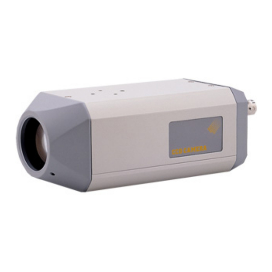
1. INTRODUCTION The auto-focus camera is a compact CCTV camera designed for easy integration into surveillance systems. The Camera's built-in 22x Optical zoom lens spells added user convenience since there is no need for separate adjustment of the focal distance. Current applications include highway traffic control, plus security surveillance in such locations as elevators and parking lots. -
Page 5: Features
2. FEATURES 1/4“ High Resolution Color CCD Camera. • Supports powerful function: Auto Iris Control (AIC), Auto White Balance (AWB), Auto Gain • Control (AGC), Auto Back Light Compensation (ABLC), Flickerless (FL) and Auto Focus (AF). 22x Optical Zoom Lens and 16x Digital Zoom. (Total 352x Zoom). •... -
Page 6: Accessories
3. ACCESSORIES • Mounting Block ×1 and Screws ×2 • Camera Control 4-pin Connector ×1 • User’s Manual ×1... -
Page 7: Precaution
4. PRECAUTION Please do not directly touch the zoom lens. If it is necessary to clean the zoom lens, use soft cloth moistened with alcohol to wipe off any dust. Please be extra careful not to shake the product. Please avoid places where frequent vibrations or shocks Do not install the product in extreme temperature conditions. -
Page 8: Name And Function Of Each Part
5. NAME and FUNCTION of EACH PART Front View Figure 5-1 Side View Figure 5-2 Rear View RS-232 RS-485 VIDEO AUDIO Figure 5-3... - Page 9 (1). Power Input:DC 12V ±10% (Recommendation 12 ±0.5V) Max 4.1W. (2). Video Output:Composite Video 1Vp-p, 75 Ohms, BNC (3). Audio Output:2Vp-p, 50 Ohms (4). Remote Control (6-pin Dry Contact Connector) / Key Control: Name Function Tele/ Zoom Tele or Up ( ) Wide/ Zoom Wide or Down ( ) Near/+...
-
Page 10: Installation
6. INSTALLATION RS-232C D-Sub Connector Camera 1 Frame GND RS-232 Interface 2 RD 3 TD 4 DTR 5 Signal GND 6 DSR 7 RTS 8 CTS 9 RI Figure 6-1 Camera RS-422 Interface 232 to 422 Converter To PC or Controller Figure 6-2 Camera... -
Page 11: Native Keyboard Installation
6.1 Native Keyboard Installation RS-485 interface is used for communicating native keyboard. Refer to Figure 6-3; connect R+ and T+ of the camera together; connect R+ and T+ of the camera to D+ of the native keyboard. Connect R- and T- of the camera together; connect R- and T- of the camera to D- of the native keyboard. -
Page 12: Operating Procedure
7. OPERATING PROCEDURE (1) Mount the camera on the mounting bracket by using the hole on the top or bottom of the camera or by using the enclosed 8mm mounting block, furnished by 2 screws. (2) Connect the Video Output to the monitor or other video device via a 75 Ohms type coaxial cable. -
Page 13: Pelco Keyboard (Or Compatible) Operation
OSD Setup Menu Mode Native Keyboard Camera Function Decrease (-) Increase (+) Cursor Up Cursor Down BRIGHTNESS+ None BRIGHTNESS- None NEAR None None Zoom TELE None Zoom WIDE None Move Joystick Left None Move Joystick Right None Move Joystick Up None Move Joystick Down None... - Page 14 OSD Setup Menu Mode PELCO Keyboard Camera Function OPEN Sub Menu Enter CLOSE Sub Menu Exit NEAR Cursor Up Cursor Down Twist Joystick clockwise or Zoom In None Twist Joystick counterclockwise or Zoom Out None Move Joystick Left Decrease (-) Move Joystick Right Increase (+) Move Joystick Up...
-
Page 15: System Setup
8. SYSTEM SETUP 8.1 OSD (On Screen Display) FORMAT OSD DISPLAY POSITION Figure 8-1... - Page 16 OSD DISPLAY DESCRIPTION FUNCTION OSD Format DESCRIPTION Non display Auto Mode FOCUS MODE Manual / Push Auto Mode Non display Back Light OFF BACK LIGHT “BLC” display BLC ON / Auto / Super BLC Mode Normal Shutter Non display (NTSC: 1 / 60, PAL: 1 / 50) “Ff”...
- Page 17 NOTE: Setting string: "BBBB, P, D, S" BBBB represent baud rate, it can be one of the following values: 2400, 4800, 9600, 19200 P represent parity, it can be one of the following values: N (None), O (Odd), E (EVEN) D represent data bits, it should be the following value: S represent stop bit, it should be the following value: For example, the following string specifies a baud rate of 9600, no parity, 8 data bits, and 1...
-
Page 18: Menu Descriptions
8.2 MENU DESCRIPTIONS MAIN MENU MENU FOCUS SET AWB SET AE SET SPECIAL SET F OSD DISP COMMUNICAT INITIAL SET EXIT Figure 8-2 SET UP THE MENU In order to display the Setup Menu on the screen, set the Menu command or press key panel. -
Page 19: Sub Menu Descriptions
8.3 SUB MENU DESCRIPTIONS FOCUS SET FOCUS MODE SET: This function is for focus mode setting. Set the mode to Auto, Manual, or Push Auto. FOCUS DISTANCE SET: This function is for selection of minimum shooting distance. Set the Focus Distance mode to 1cm, 10cm, 50cm, 1M, 3M, 5M or 10M. ZOOM START SET: This function is for selection of zoom start position. - Page 20 AWB SET WB MODE SET: This function is for changing the WB mode. Set the mode to Auto, Hue, Indoor, Outdoor, Manual, or Push Auto. AUTO: WB color temperature range = 2500°K ~ 8000°K. Manual WB: Adjust Red and Blue gain to perform a desired White Balance. PUSH AUTO: Set the WB mode to Push Auto.
- Page 21 AE SET AE MODE SET: This function is for changing the AE mode. Set the mode to AUTO, IRIS MAN, AGC MAN, or Manual. IRIS ADJUST SET: This function is available for IRIS MAN mode. Adjust the level from 56 MIN to 250 MAX. AGC MAXIMUM SET / AGC ADJUST SET: This function is available for AGC AUTO mode / AGC MAN mode.
- Page 22 BLC AREA SET: This function is available for BLC ON or AUTO BLC mode. Define the main object area that is under exposure based on the average luminance of the whole image. Set the BLC area Center (area 0), Top Small (TopS) (area1+area2), Top Large (TopL) (area1+area2+area0), Bottom Small (BottomS) (area3+area4), Bottom Large (BottomL) (area3+area4+area0), Left (area1+area3) or Right (area2+area4).
-
Page 23: Special Set
SPECIAL SET USER TITLE SET: This function is for setting up user title on screen display. Set the position of title using Near / Far Command, set the data using Tele / Wide Command. SHARPNESS ADJUST Set: Adjust the level from 0 to 15. MIRROR Set: Select the mode ON or OFF. - Page 24 F. OSD SET FUNCTION DISP ON or DISP OFF There are Focus Mode, Back Light, Shutter Speed and WBC Mode in the function display. CAMERA ID DISP ON or DISP OFF ZOOM MAG DISP ON or DISP OFF USER TITLE DISP ON or DISP OFF INIT TITLE DISP ON or DISP OFF BRIGHTNESS DISP ON or DISP OFF COMMUNICATION SET...
-
Page 25: Camera Control Command Protocol
9. Camera Control Command Protocol (For RS-232, RS-422, and RS-485) 9.1 Communication Format The communication data format from PC to Camera Data of total 6 bytes is transmitted from PC to camera. Format: Byte1 Byte2 Byte3 Byte4 Byte5 Byte6 0xC5 Code1 Code2 Code3... -
Page 26: Pc Command
The communication data format from Camera to PC Data of total 9 bytes is transmitted from Camera to PC. Format: Byte1 Byte2 Byte3 Byte4 Byte5 Byte6 Byte7 Byte8 Byte9 0xC5 Code1 Code2 Code3 Data1 Data2 Data3 Data4 C.S. Description: (Refer to 9.2 PC Command) (a) Byte 1: Camera is realized the protocol comes from PC. - Page 27 5. In case of AEmodeCNT = 0x04, the Exposure Mode becomes “MANUAL” mode. And you can adjust “IRIS level” and “AGC level” manually. 6. In case of AEmodeCNT = every other value, the Exposure Mode remains changed. BACKLIGHT Level Read Read the current BACKLIGHT level of Camera.
- Page 28 WB_CNT: This is an index counter to change the mode of White Balance 1. In case of WB_CNT = 0, the mode of White Balance becomes “AUTO” mode. 2. In case of WB_CNT = 1, the mode of White Balance becomes “HUE” mode. 3.
- Page 29 Focus Lens Position Read Read the current value of Focus lens. PC → Camera 0xC5 0x37 0x00 0x00 CAM_ID C.S. Camera → PC 0xC5 0x37 0x00 0x00 FP_CNT+1 FP_CNT 0xXX 0xXX C.S. FP_CNT+1: Upper byte of Focus lens position. FP_CNT: Lower byte of Focus lens position.
- Page 30 Memorize Zoom Lens Position for External PRESET control Memorize the Zoom lens position into the volatile “Buffer RAM” designated “Buffer RAM Index” for the external PRESET Move control. PC → Camera 0xC5 0x49 PRE_I_ZH ZPL CAM_ID C.S. Camera → PC 0xC5 0x49 PRE_I_ZH ZPL PRE_I_ZH 0xXX 0xXX 0xXX C.S.
- Page 31 2. FPL: Lower data of position value for the Focus lens. Ex. Memorize 0x21F to the Focus Lens Position in PRESET 3. 0xC5 0x4A PRE_I_FH FPL CAM_ID C.S. 0xC5 0x4A 0x32 0x1F CAM_ID C.S. Memorize Digital Zoom Position for External PRESET control Memorize the Digital Zoom position into the volatile “Buffer RAM”...
- Page 32 INDEX: Position setting index of the PRESET Buffer RAM to change Zoom, Focus & Digital Zoom position. Caution: The range of INDEX is from 0x00 to 0x07. Camera RESTART Restart the Camera’s micro controller (u-COM). PC → Camera 0xC5 0x4F 0x00 0x00 CAM_ID C.S. Camera →...
- Page 33 13. In case of INDEX = 12, the Max Power Digital Zoom = 14X. Therefore, Total Zoom = 308X. 14. In case of INDEX = 13, Max Power Digital Zoom = 15X. Therefore, Total Zoom = 330X. 15. In case of INDEX = 14, Max Power Digital Zoom = 16X. Therefore, Total Zoom = 352X. 16.
- Page 34 CAMERA). PC → Camera 0xC5 0xCC 0x00 0x00 CAM_ID C.S. Camera → PC 0xC5 0xCC 0x00 0x00 CAM_ID On/Off 0xXX 0xXX C.S. 1. CAM_ID; The Camera ID data of a CAMERA. 2. On/Off: The On/Off mode of the camera ID. 0x00: Camera ID is “OFF”...
- Page 35 Camera → PC 0xC5 0xAA 0x70 MODE 0x70 0xXX 0xXX 0xXX C.S. 1. In case of MODE = 0x01, The BACKLIGHT mode becomes ON mode. 2. In case of MODE = 0x00, The BACKLIGHT mode becomes OFF mode. Otherwise, The BACKLIGHT mode is not changed.
- Page 36 FOCUS Mode Setting Switch the FOCUS mode to AUTO, MANUAL or PUSH_AUTO according to the data of “MODE”. PC → Camera 0xC5 0xAA 0x73 MODE CAM_ID C.S. Camera → PC 0xC5 0xAA 0x73 MODE 0x73 0xXX 0xXX 0xXX C.S. 1. In case of MODE = 0x00, the FOCUS mode becomes “AUTO” mode. 2.
- Page 37 0xC5 0xAA 0x77 MWB_CTL 0x77 0xXX 0xXX 0xXX C.S. MWB_CTL: This is a data for which adjusts a HUE point at the Hue White Balance mode. Data range: 00 ~ 99 White Balance PUSH_AUTO ON/OFF Setting Switch the PUSH AUTO White Balance state to ON or OFF at PUSH AUTO White Balance mode according to the data of “MODE”.
- Page 38 BRIGHTNESS Data Setting Set the brightness level of the camera according to the data of “Brightness”. PC → Camera 0xC5 0xAA 0x7A Brightness CAM_ID C.S. Camera → PC 0xC5 0xAA 0x7A Brightness 0x7A 0xXX 0xXX 0xXX C.S. Brightness: The data for adjusting the brightness level of the camera. MENU OSD Display ON/OFF Setting Set the MENU OSD Display mode of the camera to ON or OFF according to the data of “MODE”.
- Page 39 SSC_CNT NTSC SSC_CNT NTSC 1/60 1/50 1/1100 1/1100 1/125 1/125 1/1200 1/1200 1/150 1/150 1/1300 1/1300 1/200 1/200 1/1500 1/1500 1/250 1/250 1/1600 1/1600 1/300 1/300 1/1800 1/1800 1/350 1/350 1/2000 1/2000 1/400 1/400 1/2500 1/2500 1/450 1/450 1/3000 1/3000 1/500 1/500 1/3500...
- Page 40 Camera → PC 0xC5 0xAA 0x7D AGC_CTL 0x7D 0xXX 0xXX 0xXX C.S. AGC_CTL: The data for adjusting the AGC level of the camera. Data value range from 0x1C (Minimum AGC Level) to 0xDC (Maximum AGC Level) Caution: This command is available when the Exposure Mode is “AGC MAN” or “MANUAL”. Function OSD Display Mode Change Change the Function OSD Display Mode of the camera according to the data of “OSD_DISP”.
- Page 41 Camera → PC 0xC5 0xAA 0x6E MODE 0x6E 0xXX 0xXX 0xXX C.S. 1. In case of MODE = 0x01, the Digital Zoom Mode is changed to “ON” mode. 2. In case of MODE = 0x00, the Digital Zoom Mode is changed to “OFF” mode. 3.
- Page 42 High Speed Zoom Tracking External PRESET Move Control Performs Zoom Tracking PRESET action to the targeted zoom position, memorized in the volatile PRESET Buffer RAM indicated by the “INDEX” value. In this case, the Zoom Tracking is performed quickly. PC → Camera 0xC5 0x7C INDEX 0x00 CAM_ID C.S.
- Page 43 Explanation 0: Focus Auto state. 1: Focus Manual state. 0: Camera ID OFF mode. 1: Camera ID ON mode. 0: WB Push_Auto OFF state. 1: WB Push_Auto ON state. 0: BACKLIGHT OFF state. 1: BACKLIGHT ON state. 0: FLICKERLESS OFF state. 1: FLICKERLESS ON state.
- Page 44 PC → Camera 0xC5 0xAA 0x82 0x00 CAM_ID C.S. Camera → PC 0xC5 0xAA 0x82 0x00 DEFT_CON 0xXX 0xXX 0xXX C.S. Construction of DEFT_CON data Explanation Reserved. 0: Mosaic OFF state. 1: Mosaic ON state. 0: Color ON state. 1: Color OFF state. Reserved.
- Page 45 Read the Exposure Mode Read the current Exposure Mode of the camera. The data is “AE_MODE”. PC → Camera 0xC5 0xAA 0x84 0x00 CAM_ID C.S. Camera → PC 0xC5 0xAA 0x84 0x00 AE_MODE 0xXX 0xXX 0xXX C.S. Explanation of “AE_MODE” data AE_MODE Explanation AUTO Exposure mode.
- Page 46 Read the current BRIGHTNESS data Read the current BRIGHTNESS data of the camera. The data is “Brightness”. PC → Camera 0xC5 0xAA 0x89 0x00 CAM_ID C.S. Camera → PC 0xC5 0xAA 0x89 0x00 Brightness 0xXX 0xXX 0xXX C.S. Read the current Shutter Speed Control counter value Read the current counter value to control Shutter Speed.
- Page 47 Camera → PC 0xC5 0xAA 0x8C 0x00 AGC_CTL 0xXX 0xXX 0xXX C.S. Read the MENU OSD ON/OFF status Read the current MENU OSD ON/OFF state of the camera. The data is “M_STATE”. PC → Camera 0xC5 0xAA 0x8D 0x00 CAM_ID C.S. Camera →...
- Page 48 Caution: The data of this command is valid only when the Digital Zoom mode is ON. Explanation of “DZ_MAX” data DZ_MAX Explanation The current Max Power Digital Zoom of the Camera is “x2”. The current Max Power Digital Zoom of the Camera is “x3”. The current Max Power Digital Zoom of the Camera is “x4”.
- Page 49 PC → Camera 0xC5 0x7A INDEX 0x00 CAM_ID C.S. Camera → PC 0xC5 0x7A INDEX 0x00 INDEX 0xXX 0xXX 0xXX C.S. INDEX: The value for indicating the memory position to store the zoom, focus, and digital zoom position value. The range of this value is from 0x00 to 0x7F. Slow Speed Internal Zoom Tracking PRESET Moving control Perform the Zoom Tracking PRESET action to the target zoom position slowly.
- Page 50 INDEX: The value for indicating the memory position to store the zoom, focus, and digital zoom position value. The range of this value is from 0x00 to 0x7F. Focusing Object Distance Setting Set the object distance range. PC → Camera 0xC5 0x58 Distance 0x00 CAM_ID C.S.
- Page 51 Focus Lens NEAR Direction Step Move Command This Command moves the focus lens by a specific number step in the direction of NEAR. Caution: This command is performed, when the focus mode is MANUAL or PUSH_AUTO. And is not performed during Zooming. PC →...
- Page 52 Camera ID Function OSD Display Mode On/Off Setting Command This Command decides whether or not the Camera ID Function OSD is to be displayed on the screen. PC → Camera 0xC5 0xAA 0x96 OnOff CAM_ID C.S. Camera → PC 0xC5 0xAA 0x96 OnOff 0x96 0xXX 0xXX 0xXX C.S. 1.
- Page 53 Camera → PC 0xC5 0xAA 0x9A 0x00 CAM_CON3 0xXX 0xXX 0xXX C.S. CAM_CON3: This is a status value that the camera is currently controlled. Explanation 1: High Speed Zoom Tracking Mode 1: Normal Speed Zoom Tracking Mode 1: Auto Focus Zoom Tracking Mode at MANUAL or PUSH_AUTO Focus mode Reserved.
- Page 54 Camera → PC 0xC5 0xAA 0x9C MODE 0x9C 0xXX 0xXX 0xXX C.S. 1. In case of MODE = 0x00, the back light mode becomes OFF mode. 2. In case of MODE = 0x01, the back light mode becomes ON mode. 3.
- Page 55 Red Control Gain Adjust Command This command adjusts the red control gain of the camera. PC → Camera 0xC5 0xAA 0xA4 R_Cont CAM_ID C.S. Camera → PC 0xC5 0xAA 0xA4 R_Cont 0xA4 0xXX 0xXX 0xXX C.S. R_Cont: The value, which adjusts the red control gain of the camera. Red Control Gain Read Command This command reads the current red gain of the camera.
- Page 56 Blue Control Gain Read Command This command reads the current blue gain of the camera. PC → Camera 0xC5 0xAA 0xA7 0x00 CAM_ID C.S. Camera → PC 0xC5 0xAA 0xA7 0x00 B_Cont 0xXX 0xXX 0xXX C.S. B_Cont: The value, which is currently assigned to the blue control gain of the camera. MOSAIC Digital Effect On/Off control Command This command switches the MOSAIC digital effect mode to ON or OFF according to ONOFF.
- Page 57 Distance: The index value, which indicates the current object distance range that the camera can be focused. 1. In case of Distance = “0x00”, the Focusing range = From 1 cm To infinite 2. In case of Distance = “0x01”, the Focusing range = From 10 cm To infinite 3.
- Page 58 Camera → PC 0xC5 0x66 INDEX CHAR INDEX 0xXX 0xXX 0xXX C.S. 1. INDEX: The index value, which indicates the character position of the user title string in order to edit. The range of this value is from 0x00 to 0x09. 2.
- Page 59 PC → Camera 0xC5 0x6B INDEX ONOFF CAM_ID C.S. Camera → PC 0xC5 0x6B INDEX ONOFF INDEX 0xXX 0xXX 0xXX C.S. INDEX: The index value to select whether or not to display the function OSD. ONOFF: The value, which indicates whether the selected function OSD is or not displayed. 1.
-
Page 60: Key Code Table
Camera → PC 0xC5 0xAA 0x55 0x00 0x55 0xXX 0xXX 0xXX C.S. 9.3 Key Code Table Key Variable Key Code Description KN_NOT 0x00 No key function will operate. Perform Zoom Tracking to TELE side by slow speed. In case of KN_TELE 0x01 displaying the MENU, it operates as the “MENU selection scroll up“. - Page 61 KN_OSD 0x24 Switch the Key function OSD (ON / OFF). KN_MENU 0x25 Switch the main MENU (ON / OFF). KN_M_UP 0x27 Increase the data of a selected item on the main MENU. KN_M_DN 0x28 Decrease the data of a selected item on the main MENU. KN_POWER 0x32 Switch the power of the Camera (ON / OFF).
- Page 62 MENU. Scroll down the MENU item. KN_RS_AMkey Use for RS-232C Serial Communication: Switch the Focus mode 0x51 _SET “AUTO/MANUAL”, or “Push AUTO“. KN_RS_INIT_S Use for RS-232C Serial Communication: Reset the Camera mode to 0x52 default value. KN_RS_SRPup 0x53 Use for RS-232C Serial Communication: Scroll up the Sharpness level. KN_RS_SRPdn 0x54 Use for RS-232C Serial Communication: Scroll up the Sharpness level.
-
Page 63: Specifications
10. SPECIFICATIONS Note: Design and specifications are subject to change without prior notice. Signal System NTSC Color PAL Color Image Pick-up Device SONY 1/4” Super HAD High-Resolution Color CCD sensor Total Pixels No. 811 (H) x 508 (V) 410K 795 (H) x 596 (V) 470K 768 (H) ×... - Page 64 MEMO...
Need help?
Do you have a question about the TBK-6004CHZ and is the answer not in the manual?
Questions and answers