ESAB Powercut 1600 Service Manual
Plasmarc cutting package
Hide thumbs
Also See for Powercut 1600:
- Instruction manual (70 pages) ,
- Instruction manual (24 pages) ,
- Instruction manual (28 pages)
Table of Contents
Advertisement
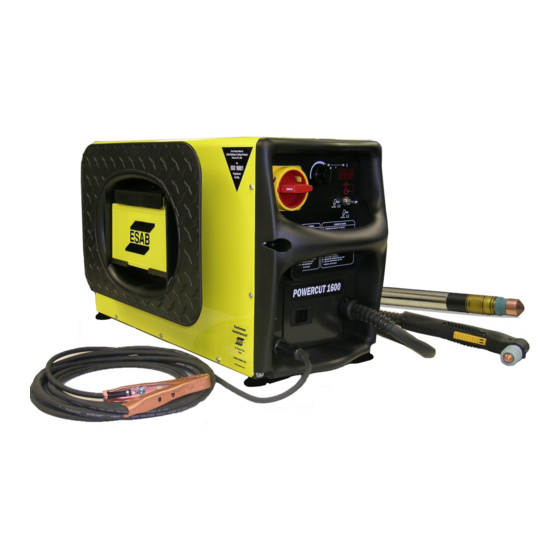
Powercut 1600
Plasmarc Cutting Package
Service Manual
This manual provides service / troubleshooting
instructions for PC1600 consoles beginning with
Serial Number .........PORJ815099
ending with Serial Number ....PORJ852108
Manual # 0558008016- Rev. 0
PART NO
0558007230
0558007230F
0558007237
0558007636
0558007234
0558008323
11/2008
DESCRIPTION
PC1600 230/460V Console
PC1600 230/460V BL Console
PC1600 575V BL Console
PC1600 400V Console
PC1600 400V CE Console
PC1600
460V Console
(BL = Bilingual)
Advertisement
Table of Contents

Related Manuals for ESAB Powercut 1600


Summary of Contents for ESAB Powercut 1600
-
Page 1: Service Manual
Powercut 1600 Plasmarc Cutting Package PART NO DESCRIPTION 0558007230 PC1600 230/460V Console Service Manual 0558007230F PC1600 230/460V BL Console 0558007237 PC1600 575V BL Console This manual provides service / troubleshooting instructions for PC1600 consoles beginning with 0558007636 PC1600 400V Console Serial Number ..PORJ815099... -
Page 2: User Responsibility
This Service Manual is for experienced technicians. If you are not fully familiar with the principles of operation and safe practices for arc welding and cutting equipment, we urge you to read our booklet, “Precautions and Safe Practices for Arc Welding, Cutting, and Gouging,”... - Page 3 SECTIONS SAfETY INTRODuCTION SPECIfICATIONS DESCRIPTION Of OPERATION SChEMATIC SECTION MAP MAIN POwER SwITCh CONTROl TRANSfORMER INPuT bRIDgE CONTACTOR VOlTAgE SElECTOR SwITCh MAIN TRANSfORMER OuTPuT DIODES PlASMA CONTROl / DISPlAY bOARD PCb1 fIlTERS l1-l2 POwER bOARD PCb2 4.10 POwER DRIVER PCb3 - PCb4 4.11 ThERMAl SwITCh 4.12...
-
Page 4: Table Of Contents
TAblE Of CONTENTS Section / Title Page Introduction ..............12 3.0 Power Specifications . - Page 5 TAblE Of CONTENTS Section / Title Page 4.10.10 Power Board_PCB2 Output Circuit (0558038315) ......71 4.10.11 Power Board_PCB2 V-Arc Circuit (0558038315).
- Page 6 SECTION 1 SAfETY PRECAuTIONS WARNING: These Safety Precautions are for your protection. They summarize FIRES AND EXPLOSIONS -- Heat precautionary information from the refer- from flames and arcs can start ences listed in Additional Safety Informa- fires. Hot slag or sparks can also tion section.
- Page 7 SECTION 1 SAfETY PRECAuTIONS fined, or if there is danger of falling. Welders having pacemakers should consult their physician before welding. EMF may interfere Be sure the power source frame (chassis) with some pacemakers. is connected to the ground system of the input power.
- Page 8 SECTION 1 SAfETY PRECAuTIONS If you develop momentary eye, nose, or Standard P-1, “Precautions for Safe Handling of throat irritation while operating, this is an indication Compressed Gases in Cylinders”, which is avail- that ventilation is not adequate. Stop work and take able from Compressed Gas Association, 1235 Jef- necessary steps to improve ventilation in the work ferson Davis Highway, Arlington, VA 22202.
- Page 9 SECTION 1 SAfETY PRECAuTIONS ADDITIONAL SAFETY INFORMATION -- For more information on safe practices for electric arc welding and cutting equipment, ask your supplier for a copy of “Precautions and Safe Practices for Arc Welding, Cutting and Gouging”, Form 52-529. The following publications, which are available from the American Welding Society, 550 N.W.
- Page 10 SECTION 1 SAfETY PRECAuTIONS When plasma cutting stainless steel, you must comply with the OSHA standard to protect your employees from Hexavalent Chromium exposure. Engineering control must be used to reduce exposures to safe levels (in compliance with the new PEL). The specific details of the standard are complex and may require the assistance of an occupational health professional to reach full compliance For additional information about Hexavalent Chromium contact your occupational health professional and read the OSHA web page at http://www.osha.gov/SLTC/hexavalentchromium/...
- Page 11 SECTION 1 SAfETY PRECAuTIONS CANCER HAZARD; CAN DAMAGE SKIN, EYES, NASAL PASSAGES, AND LUNGS; AUTHORIZED PERSONNEL ONLY; RESPIRATORS MAY BE REQUIRED. CHROMIUM (VI) Cr(VI) HEXAVALENT CHROMIUM) On February 28, 2006, the Occupational Safety and Health Agency (OSHA) pub- lished a revised Hexavalent Chromium Cr(VI) is a toxic standard to protect workers from the potential chemical component within fume and...
-
Page 12: Introduction
2.1 General The Powercut 1600 is a compact plasma cutting system. As shipped, the system is fully assembled and ready to cut after being connected to input power and a source of compressed air (350 cfh @ 90 psi / 6.2 bar). -
Page 13: Power Specifications
SECTION 3 SPECIfICATIONS POwER SPECIfICATIONS Specifications Specifications: PowerCut -1600 Cuts 1-1/2 in. (38 mm); severs 1-3/4 in. (45 mm) 1 ph. Input 208/230 vac, 1 ph, 50/60 Hz, 82/74 A 1 ph. Output 90 amps @ 40% duty cycle 208/230 vac, 3 ph, 50/60 Hz, 44/40 A 230/460 vac, 3 ph, 50/60 Hz, 40/27 A 3 ph. -
Page 14: Power Up Sequence
SECTION 3 SPECIfICATIONS Power Up Sequence Power up Sequence of Events When the machine is turned on, a self diagnostic test is performed to determine the condition of the torch. Sequence of events The operator turns on the power switch The Power Board PCB-1 determines if the input voltage is correct and connects input power. -
Page 15: Power Up Sequence
SECTION 3 SPECIfICATIONS Power Up Sequence When the operator closes the torch switch the following occurs: The Torch Trigger circuit is engaged Power Board relay RL3, the Mains Contactor Relay, closes. The Mains Contactor Closes Power board Relay RL1, the gas solenoid relay, closes. The gas valve opens Full buss voltage is available 2 seconds of preflow... -
Page 16: Machine Operation Flowchart
SECTION 3 SPECIfICATIONS Machine Operation Flowchart... -
Page 17: Component Locator
SECTION 3 SPECIfICATIONS Component locator PC1600 Components Symbol Description Section # 4. INDUCTOR INPUT REACTOR LINE 3 PHASE INDUCTOR OUTPUT TRANSFORMER MAIN TRANSFORMER CONTROL BRIDGE RECTIFIER 110A 1600V Q101,102 IGBT DUAL 150A 600V Q103 IGBT 50A 1200V D101,102 DIODE MODULE 100A 600V PCB1 PC BOARD - CONTROL / DISPLAY PCB2... -
Page 18: Machine Testing / Troubleshooting / Service
SECTION 4 DESCRIPTION Of OPERATION MAChINE TESTINg / TROublEShOOTINg / SERVICE Schematic Section Map 230/460V- 0558007542... - Page 19 SECTION 4 DESCRIPTION Of OPERATION Schematic Section Map - 0558007542...
-
Page 20: Schematic Section Map 400V/400V Ce- 0558007546
SECTION 4 DESCRIPTION Of OPERATION Schematic Section Map 400V/400V CE- 0558007546... - Page 21 SECTION 4 DESCRIPTION Of OPERATION Schematic Section Map - 0558007546 400V/400V CE...
-
Page 22: Schematic Section Map 575V- 0558007544
SECTION 4 DESCRIPTION Of OPERATION Schematic Section Map 575V- 0558007544... - Page 23 SECTION 4 DESCRIPTION Of OPERATION Schematic Section Map - 0558007544...
-
Page 24: Main Power Switch S1 (36107)
SECTION 4 DESCRIPTION Of OPERATION Main Power Switch S1 (36107) The main Power Switch is located on the front panel of the unit and passes main input power to the unit. The switch is a triple pole, single throw, rotary type switch, rated for 63 amps of input current at 690 VAC. T6 current transformer, located on the B leg of the S1 output is used to monitor for a single phasing condi- tion. -
Page 25: Control Transformer T2 (0558007188)
Control Transformer T2 (0558007188) The auxiliary control transformer is used to step-down the input voltage to levels that can be used as sup- ply voltages for the logic circuits in the PC1600. Since the PowerCut 1600 is available in with different input voltage configurations, the control transformer has a multiple tap primary to allow it to be used in all ver- sions. - Page 26 SECTION 4 DESCRIPTION Of OPERATION Control Transformer T2 (0558007188) Transformer T2 (0558007188) Resistance Lead Color Input Voltage Leads Ohms Common GREY H1 - H2 < 1 ohm BLUE H1 -H3 < 1 ohm WHITE H1 - H4 < 1 ohm ORANGE H1 - H5 <...
- Page 27 SECTION 4 DESCRIPTION Of OPERATION Control Transformer T2 (0558007188)
- Page 28 SECTION 4 DESCRIPTION Of OPERATION 4.2.1 Axial fan (951182) The side mounted fan M1 is used to circulate cooling air across the active devices, (the IGBTs, IBR and D101 and D102) inside the cabinet. The fan starts when the torch trigger is depressed and will continue to run for up to seven minutes after the cut has ceased.
-
Page 29: Input Bridge (0558007068 / 0558007077))
SECTION 4 DESCRIPTION Of OPERATION Input Bridge (0558007068 / 0558007077)) The input bridge is a 3 phase, full wave rectifier, which converts the AC input voltage to DC. The device is designed to deliver a maximum current of 160 Amps of forward current. Primary AC power enters the rectifier where it is rectified by the six diodes inside BR1. The rectified output is coupled to the buss supply capacitors and the L1 input inductor. A “precharge” Inrush circuit is mounted to the output of L1 and is in parallel with the Main Contactor. This circuit allows the Buss supply to charge gradually during initial power up. - Page 30 SECTION 4 DESCRIPTION Of OPERATION Input Bridge (0558007068/0558007077))
-
Page 31: Contactor K1 (950247)
SECTION 4 DESCRIPTION Of OPERATION Contactor K1 (950247) The Main Contactor Relay K1 is the main power relay on this unit. When the torch switch is closed, the con- trol board PCB1 supplies 24VAC to the coil of the relay. This allows the relay to energize which allows full power to be applied to the filter buss. -
Page 32: Voltage Selector Switch Sw2 (0558007183)
SECTION 4 DESCRIPTION Of OPERATION Voltage Selector Switch Sw2 (0558007183) The Voltage Selector Switch is a three position switch designed to alter the configuration of the filter bus to accommodate 230 VAC or 460 VAC input voltages. This switch is only in the 230/460 VAC selectable models. The filter caps are configured in two different ways in the PC1600 230/460 model, dependant upon the input voltage. The power selector switch SW2 will place the four filter capacitors in either a series configu- ration or in a parallel pair configuration. The Voltage Selector switch is a three position switch with a center “Off” position. If this switch is changed during normal operation, the system will shut down to prevent damage to the unit. -
Page 33: Main Transformer T1 (36586)
SECTION 4 DESCRIPTION Of OPERATION Main Transformer T1 (36586) The Main Transformer T1 accepts the 18.5 KHz AC power from the IGBTs and steps the voltage down be- fore sending it to the output diodes where it is rectified to DC before being sent out to the torch. - Page 34 SECTION 4 DESCRIPTION Of OPERATION Main Transformer T1 Main Transformer T1 (0558007189 / 0558007190)
- Page 35 blANK...
-
Page 36: Output Diodes D101, D102 - (951185)
SECTION 4 DESCRIPTION Of OPERATION Output Diodes D101, D102 – (951185) The two output diode modules consist of two diodes in each module connected to make a full wave bridge. These modules are each rated at 100 Amps of forward current at 600 VDC. D101- D102 DIODE RED LEAD BLACK LEAD RESISTANCE (OHMS) -
Page 37: Pcb1 Control/Display Board (0558038317)
SECTION 4 DESCRIPTION Of OPERATION PCB1 Control/Display Board (0558038317) Description: The main control board is responsible for most of the control functions of the PC1600. This board controls the Pulse Width Modulator, CNC interface, power up sequence, gas pressure control, error signals and the display. - Page 38 SECTION 4 DESCRIPTION Of OPERATION PCB1 Control Board (0558038317)
- Page 39 SECTION 4 DESCRIPTION Of OPERATION PCB1 Control Board (0558038317) PCB1...
-
Page 40: Pcb1_Bias Supplies (0558038317)
SECTION 4 DESCRIPTION Of OPERATION 4.8.1 PCB1_Bias Supplies (0558038317) POWER The Board receives +15 VDC and -15 VDC from the power board via the ribbon cable at J1. The +15 VDC is connected on J1 pins 1 -4 (to divide the current among the 4 conductors) and passed to the +5VDC sup- ply circuit and also distributed to the different circuits on the board. -
Page 41: Pcb1_Display (0558038317)
SECTION 4 DESCRIPTION Of OPERATION 4.8.2 PCB1_Display (0558038317) The Main control board microcontroller outputs the digital signals to the display driver chips. These chips then drive the displays mounted on the control board. -
Page 42: Pcb1_Error Amp / Current Reference (0558038317)
SECTION 4 DESCRIPTION Of OPERATION 4.8.3 PCB1_Error Amp / Current Reference (0558038317) The Control board sets the current output level and receives the error signals from the hall sensors mount- ed on the power board. The control board micro controller receives the current reference input current reference circuit and then outputs that on U5 pin 47 as the SDO signal. -
Page 43: Pcb1_Mode Switches (0558038317)
SECTION 4 DESCRIPTION Of OPERATION 4.8.4 PCB1_Mode Switches (0558038317) The Mode select switch (SW4) is a three position switch used to determine the mode of machine operation. In the up position the unit is in “Gas Test” mode, allowing air to flow through the torch for setting inlet pres- sures. In the center position, Normal Mode, the unit is in “Operate Mode. In the down position,(Trigger Lock) the torch trigger can be released after an arc is established and the arc will continue until the trigger is activated and released a second time. -
Page 44: Pcb1_Protection Circuit (0558038317)
SECTION 4 DESCRIPTION Of OPERATION 4.8.5 PCb1_Protection Circuit (0558038317) The Protection Circuit is designed to prevent the PC1600 from producing output current without a trigger signal present. The comparator circuit senses if output current is above zero when the pwm_engage signal is not present. -
Page 45: Pcb1_Gas Test Operate Switch (0558038317)
SECTION 4 DESCRIPTION Of OPERATION 4.8.6 PCB1_Gas Test Operate Switch (0558038317) The Display switch on the PCB1 control board allows the operator to choose the units of measurement for the Gas, in Pounds per Squire Inch (PSIG) or in (Bars) to be displayed on the front panel LED display. SW1-2 has no function. -
Page 46: Pcb1_Pwm Circuit (0558038317)
SECTION 4 DESCRIPTION Of OPERATION 4.8.7 PCb1_PwM Circuit (0558038317) PWM / IGBT Gating signal This section controls the frequency and width of the gating signal supplied to the IGBTs. The circuit receives the current reference signal from the current reference and error amplifier. This circuit is triggered on from the microcontroller. In the event that there is an over current condition the PWM chip can be shut down from either the microcontroller or from the Protection circuit (see Protection Circuit section XX) The PWM circuit receives an enable signal from the microcontroller chip to begin the output of pulses that... -
Page 47: Pcb1_Rs232 Input (0558038317)
SECTION 4 DESCRIPTION Of OPERATION 4.8.8 PCb1_RS232 Input (0558038317) Serial Input Circuit The Serial Input circuit is used for the Power Board PCB2 to communicate to the Main Control Board. This is an RS232 interface and is used primarily for the Power Board to identify itself to the Main Control board. -
Page 48: Pcb1_Current Reference (0558038317)
SECTION 4 DESCRIPTION Of OPERATION 4.8.9 PCB1_Current Reference (0558038317) The output current level of the PC1600 is set from the board mounted potentiometer (R69) that extends through the front panel of the console. The wiper of this pot is connected to the microcontroller through resistor R468. The pot is connected across 5 volts and ground. -
Page 49: Pcb1_Programming Port(0558038317)
SECTION 4 DESCRIPTION Of OPERATION 4.8.10 PCb1_Programming Port(0558038317) The programming port on the board is used to program the main control board microcontroller at the fac- tory. Field programming of the unit is not necessary. 4.8.11 PCB1_Thermal Sensing Circuit (0558038317) The Main Control Board has a temperature sensing circuit built into it for circuit protection. -
Page 50: Pcb1_I/O (0558038317)
SECTION 4 DESCRIPTION Of OPERATION 4.8.12 PCb1_I/O (0558038317) The control board sends and receives signals across the two ribbon cables connecting the Main Control board to the Power Board. These two ribbon cables connected to the Main Control Board at J1 and J2 are the I/O bus of the unit. -
Page 51: Pcb1_Microcontroller U5 (0558038317)
SECTION 4 DESCRIPTION Of OPERATION 4.8.12 PCb1_I/O (0558038317) J1 I/O Values Signal Value +15 VDC +15 VDC +15 VDC +15 VDC +15 VDC -15 VDC -15 VDC -15 VDC Closes the Bus Charger Relay K1 on the Power Board Bus Charger PCB2 Closes the Mains Contactor Relay RL3 on the Power MainsContactor... - Page 52 SECTION 4 DESCRIPTION Of OPERATION 4.8.14 PCB1 Layout (0558038317)
- Page 53 SECTION 4 DESCRIPTION Of OPERATION 4.8.15 PCb1 bOM (0558038317) PCb1 COMPONENTS ITEM QTY DESCRIPTION SYMbOl DRILLED BOARD CAP, NET. 9 PIN SIP, 0.01uF CN1,CN2 CAP, 4.7uF, 50VDC, ALUM C1,C3 C2,C5,C7,C15,C19,C21,C25,C29, CAP, 0.22uF, 100VDC, CER C30,C32,C40,C44,C48 CAP, 0.0068uF, 100VDC, MET-POLY C4,C13 C6,C17,C18,C23,C24,C31,C41,C4 CAP, 0.01uF, 100VDC, FILM 2,C50,C51,C52,C53...
- Page 54 SECTION 4 DESCRIPTION Of OPERATION 4.8.15 PCb1 bOM (0558038317) PCb1 COMPONENTS ITEM QTY DESCRIPTION SYMbOl RES, 10K, .25W, 1% R5,R19,R52,R59,R73,R78,R84,R87 RES, 4.99K, .25W, 1% R6,R18,R35,R36,R39,R40,R46,R48,R49,R64 R8,R13,R47,R53,R55,R62,R63,R68,R72,R75, RES, 499, .25W, 1% R79,R88,R94,R95,R96,R97 RES, 15K, .25W, 1% R9,R74 RES, 4.02K, .25W, 1% RES, TRIMPOT, 1K R16,R29 RES, 11.5K, .25W, 1%...
-
Page 55: Input Inductor L1 (0558007149/ / 0558007151)
SECTION 4 DESCRIPTION Of OPERATION Input Inductor l1 (0558007149/ / 0558007151) 0558007149 Input Inductor L1 The Input Inductor L1 is a line reactor inductor used to filter out line noise in the 400 and 575 VAC units. This is a three gang unit of three 170 micro-Henrys capable of passing 22 amps of current. 0558007151 Input Inductor The Input Inductor L1 is a line reactor inductor used to filter out line noise in the 230 and 460 VAC units. This is a 300 micro-Henry, 150 Amp unit. -
Page 56: Output Inductor (0558007152)
SECTION 4 DESCRIPTION Of OPERATION 4.9.1 Output Inductor (0558007152) The output inductor L2 is used to filter the DC output of the PC1600. The inductor is a 600 micro Henry unit designed to resist changes in the output of the PC1600. -
Page 57: Power Pc Board (0558038315)
SECTION 4 DESCRIPTION Of OPERATION 4.10 Power PC Board (0558038315) The power board in the PC1600 allows the power connections to be made in a solid, central way that makes short power runs with hi power carrying capacity. All of the power carrying components are mount- ed to PCB2. -
Page 58: Power Pc Board Schematic (0558038315)
SECTION 4 DESCRIPTION Of OPERATION 4.10.1 Power PC Board Schematic (0558038315) 4.10... - Page 59 SECTION 4 DESCRIPTION Of OPERATION 4.10.1 Power PC Board Schematic (0558038315) 4.10...
-
Page 60: Power Pc Board Schematic 2 (0558038315)
SECTION 4 DESCRIPTION Of OPERATION 4.10.2 Power PC Board Schematic 2 (0558038315) 4.10... -
Page 61: Power Board_Pcb2 Bias Supply Circuit (0558038315)
SECTION 4 DESCRIPTION Of OPERATION 4.10.3 Power Board_PCB2 Bias Supply Circuit (0558038315) The Bias supply circuit provides the power necessary to operate the onboard circuitry of the PC1600. This section provides three output voltages to the unit; +15VDC, -15VDC and +5 VDC. Two 18 VAC inputs are applied to the board at J20 Pins 4, 5 and 6, With pin 5 being the grounded center tap off the transformer. - Page 62 SECTION 4 DESCRIPTION Of OPERATION 4.10.3 Power Board_PCB2 Bias Supply Circuit (0558038315) 4.10 PCb2 bIAS SuPPlY TEST POINTS Test point Reference Point Value +15VDC +5VDC -15VDC J20 pin 4 J20 Pin 5 18 VAC J20 pin 6 J20 Pin 5 18 VAC J20 pin 4 J20 Pin 6...
-
Page 63: Power Pc Board Over Current Protection (0558038315)
SECTION 4 DESCRIPTION Of OPERATION 4.10.4 Power PC Board Over Current Protection (0558038315) The power board uses a pair of current transformers to detect an over current condition on the output of the PC1600. In the event the output exceeds the rated current, the induced signal in the transformers shuts down the power circuit at the control board microcontroller. -
Page 64: Power Pc Board_Pilot Arc / Igbt Driver Circuit (0558038315)
SECTION 4 DESCRIPTION Of OPERATION 4.10.5 Power PC Board_Pilot Arc / IgbT Driver Circuit (0558038315) The Pilot Arc IGBT is gated on from the Main Power board PCB-2 via an IC on the power board. The Pilot Arc IGBT is gated on from U9 Pin 7. This output is enabled when the microcontroller toggles on the PA relay signal to U9 pin 3. -
Page 65: Power Pc Board Single Phase Detection (0558038315)
SECTION 4 DESCRIPTION Of OPERATION 4.10.6 Power PC Board Single Phase Detection (0558038315) The power board monitors the the input power for loss of a phase when in three phase operation. This is important as the microcontroller monitors the output duty cycle of the machine. The PC1600 is rated for 60% duty cycle at 90 amps of output current in three phase operation, and 40% duty cycle at 90 amps of output current in single phase operation. -
Page 66: Power Board_Pcb2 Control Relays (0558038315)
SECTION 4 DESCRIPTION Of OPERATION 4.10.7 Power Board_PCB2 Control Relays (0558038315) The Power Board has seven relays mounted on it. One is used as part of the Inrush circuit, and will be dis- cussed there (See section 4.10.12, Inrush circuit) The remaining relays RL1 –... -
Page 67: Power Board_Pcb2 Control Relays (0558038315)
SECTION 4 DESCRIPTION Of OPERATION 4.10.7 Power Board_PCB2 Control Relays (0558038315) 4.10... -
Page 68: Power Board_Pcb2 Voltage Selection Circuit (0558038315)
SECTION 4 DESCRIPTION Of OPERATION 4.10.8 Power Board_PCB2 Voltage Selection Circuit (0558038315) The input voltage selection is controlled by the, manually set, position of S2 however the voltage selection circuit on the power board will tell the power board micro-controller that the input power is 230 or any other voltage. - Page 69 SECTION 4 DESCRIPTION Of OPERATION 4.10.8 Power Board_PCB2 Voltage Selection Circuit (0558038315) The input voltage selection is controlled by the, manually set, position of S2 however the voltage selection circuit on the power board will tell the power board micro-controller that the input power is 230 or any other voltage.
-
Page 70: Power Board_Pcb2 Cnc Interface (0558038315)
SECTION 4 DESCRIPTION Of OPERATION 4.10.9 Power Board_PCB2 CNC Interface (0558038315) The PC1600 is designed to be used in a mechanized environment. The CNC interface connector J8 is used to connect to the Remote board PCB6, which will interface with a CNC via the J2 Amphenol plug. The J8 connector passes all signals but one, the external reference signal, to the main control board PCB1 through the PCB2 J4 - PCB1 J1 ribbon cable. -
Page 71: Power Board_Pcb2 Output Circuit (0558038315)
SECTION 4 DESCRIPTION Of OPERATION 4.10.10 Power Board_PCB2 Output Circuit (0558038315) The Output Circuit on the power board consists of the rectifier diodes, the snubber, the output inductor and a pair of Hall sensors. The output diodes D103 and 104 are connected directly to the power board. AC Power from the output transformer is connected to these two diodes at the negative terminals. This 18 KHz output is rectified to DC and then passed through the Hall sensors and out to the Electrode, Pilot Arc Lead and Work lead. The Hall devices sense the current level and send a current sense signal to the control board where it is used internally by the microprocessor and sent to the display board. -
Page 72: Power Board_Pcb2 V-Arc Circuit (0558038315)
SECTION 4 DESCRIPTION Of OPERATION 4.10.11 Power Board_PCB2 V-Arc Circuit (0558038315) The V-Arc circuit is designed to notify the microcontroller on the Control board PCB1 of a low output volt- age situation. Voltage input from the two tertiary windings is connected to the Power board PCB2. This square wave AC is divided and connected to an electronic rectifier that outputs a DC reference voltage that is connected to the Microcontroller of PCB1. -
Page 73: Power Board_Pcb2 Inrush Circuit (0558038315)
SECTION 4 DESCRIPTION Of OPERATION 4.10.12 Power Board_PCB2 Inrush Circuit (0558038315) The Inrush circuit is designed to allow the filter buss to charge up at a lower current level so that when the unit begins cutting the initial current draw does not cause an excessive current surge condition which could damage the unit. When the on board relay K1 closes, the filter capacitors charge through the thermistors R62 and R67. These two thermistors restrict the amount of current drawn by the filter caps during their initial charge. When the torch switch closes the control board PCB1 will then close the mains contactor K1 on the chassis to allow full output current to be drawn through the mains contactor. -
Page 74: Power Board_Pcb2 Pressure Transducer (0558038315)
SECTION 4 DESCRIPTION Of OPERATION 4.10.13 Power Board_PCB2 Pressure Transducer (0558038315) The pressure transducer circuit provides the voltage to operate the pressure transducer and accepts the gas pressure signal back from the device. This signal is then passed to the Main Control board. The pressure transducer receives +5 volts DC across J10 pin 3 (+5 VDC) and pin 2 (DC common) The sig- nal is returned from the transducer on pin 1. -
Page 75: Power Board_Pcb2 Relay Boost Circuit (0558038315)
SECTION 4 DESCRIPTION Of OPERATION 4.10.14 Power Board_PCB2 Relay Boost Circuit (0558038315) The Relay Boost circuit provides a source of power to trip the source voltage relays in the event that the AC three phase input voltage is below 210 VAC in the 230 VAC mode. In the event that the input power is low Q7 is turned on and conducts sending source voltage down to Q8. -
Page 76: Power Board_Pcb2 Torch Trigger Circuit (0558038315)
SECTION 4 DESCRIPTION Of OPERATION 4.10.15 Power Board_PCB2 Torch Trigger Circuit (0558038315) The Torch Trigger circuit consists of a 24 VAC signal that is rectified and passed to an opto isolator. The output of the opto isolator is then connected to the to the control board as the START signal. 24VAC is sent out on J12 pin 2 and routed to either the PT38 torch trigger or to a CNC. Once the torch switch is closed, the 24VAC is returned on J9 pin 2 and sent to D3, a full wave bridge. This rectifies the AC signal and sends DC power out to the opto-isolator U7 to fire it. Once the opto-isolator is fired, the output of U7 pin 5 is then sent to the control board via J4 pin 17. -
Page 77: Buss Supply/Igbt
SECTION 4 DESCRIPTION Of OPERATION 4.10.16 Buss Supply/IgbT 4.10... - Page 78 SECTION 4 DESCRIPTION Of OPERATION 4.10.16 Power Board_PCB2 Filter Buss/IgbT Circuit (0558038315) The Inverter blocks of the PC1600 is where the stored energy in the buss supply (DC power) is converted to AC and supplied on to the output bridge. Two half bridge inverters are used (allows 230/460 switching) and the output from them is combined at the secondary of the main transformers (T1-A and T1-B).
- Page 79 SECTION 4 DESCRIPTION Of OPERATION 4.10.16 Buss Supply Note: In the early models of the PC1600, the power board labeled the Buss supply capacitors with num- bers that are different than the schematic. Conversion Information: Early model label Current models C104 C102 C103...
- Page 80 SECTION 4 DESCRIPTION Of OPERATION 4.10.16 Filter Buss The drawing below represents the output of the input bridge BR1. The bulk of the filtering is done when the capacitors C37,C40, C44, C47 charge. These large value capaci- tors act as a well, resisting changes in voltage with an ebb and flow effect, charging and discharging in contrast to the rise and fall of their input voltage. A graphical representation of this is shown in the drawing below.
- Page 81 SECTION 4 DESCRIPTION Of OPERATION 4.10.16 Power Board_PCB2 Filter Buss/IGBT (0558038315) When the converter is on, the IGBT circuit delivers an 18.5 KHz AC power to the main transformers. The IGBTs are gated on by signals from the driver boards and regulate the output of the PC 1600 (see Section 4.10.21).
-
Page 82: Power Board_Pcb2 Microcontroller Circuit (0558038315)
SECTION 4 DESCRIPTION Of OPERATION 4.10.17 Power Board_PCB2 Microcontroller Circuit (0558038315) The Microcontroller on the Power Board is responsible for the voltage selection logic and for identifying itself to the main control board PCB1 across the serial interface. Pulses for the Pilot Arc IGBT driver are developed here and sent to the driver circuit. -
Page 83: Power Board_Pcb2 Thermal Switch Circuit (0558038315)
SECTION 4 DESCRIPTION Of OPERATION 4.10.18 Power Board_PCB2 Thermal Switch Circuit (0558038315) The Thermal switch circuit supplies +15 VDC out to the Thermal switch. This is then passed through the thermal switch and returned to the power board where the voltage is passed to ground. The output of this circuit is a logic low that is sent to the microcontroller on the Main Control Board PCB1. -
Page 84: Power Board_Pcb2 Gate Driver Circuit (0558038315)
SECTION 4 DESCRIPTION Of OPERATION 4.10.19 Power Board_PCB2 Gate Driver Circuit (0558038315) The gate driver circuit accepts the gate pulses from the control board. Here the 19 KHz pulsed signals are buffered and then sent to the IGBT driver boards. Gate pulses from the control board are input on J7 pins 1 and 3. -
Page 85: Power Board_Pcb2 Rs232 Interface (0558038315)
SECTION 4 DESCRIPTION Of OPERATION 4.10.20 Power Board_PCB2 RS232 Interface (0558038315) The control board has an RS232 interface built into it that connects to the control board through the J7 ribbon cable header (header J2 on the control card). This is used for communication between the power board controller and the main controller. -
Page 86: Power Board_Pcb2 Layout (0558038315)
SECTION 4 DESCRIPTION Of OPERATION 4.10.21 Power Board_PCB2 Layout (0558038315) 4.10 PCb2 POwERbOARD COMPONENTS ITEM QTY DESCRIPTION SYMbOl DRILLED BOARD BRIDGE, 3A, 400V, GBPC 104 C4,C3,C11,C13,C18,C21,C27,C33,C57,C58, CAP, 680pF, 100VDC, MET-POLY C59,C62,C63,C70 C2,C6,C10,C12,C16,C23,C32,C36,C49,C60, CAP, 0.22uF, 100VDC, CERAMIC C82,C85,C86,C90,C91,C92 C1,C28,C29,C35,C67,C74,C75,C78,C84,C8 CAP, 0.1uF, 100VDC, MET-POLY 8,C89 CAP, 330pF, 200VDC, CERAMIC C5,C7,C34,C42,C43... - Page 87 SECTION 4 DESCRIPTION Of OPERATION 4.10.21 Power Board_PCB2 BOM (0558038315) PCb2 POwERbOARD COMPONENTS ITEM QTY DESCRIPTION SYMbOl CAP, 0.001uF, 100VDC, MET-POLY C14,C15 CAP, 0.01uF, 100VDC, MET-POLY C17,C19,C20,C24,C25,C53 CAP, 22uF, 63VDC, ELECT. C22,C61 CAP, 47uF, 35VDC, ELECT. C30,C41,C87 CAP, 0.0047uF, 1000VDC, EMI C26,C31 CAP, 2.2uF, 400VDC, MET-POLY C38,C39,C45,C46...
- Page 88 SECTION 4 DESCRIPTION Of OPERATION 4.10.21 Power Board_PCB2 BOM (0558038315) PCb2 POwERbOARD COMPONENTS ITEM QTY DESCRIPTION SYMbOl RELAY, POTTER BRUMFIELD T92 TRANSFORMER, CURRENT, CC040616 L1,L2 INDUCTOR, 115uH, PE53820 L4,L5 CONN. POWER, AMP TRANSISTOR, FET, IRFD110 Q1,Q2,Q4 TRANSISTOR, FET, IRLD014PbF Q3,Q8 TRANSISTOR, NPN, SILICON, MJE243 TRANSISTOR, PNP, SILICON, BC640 TRANSISTOR, FET, IRFD9120...
- Page 89 SECTION 4 DESCRIPTION Of OPERATION 4.10.21 Power Board_PCB2 BOM (0558038315) PCb2 POwERbOARD COMPONENTS ITEM QTY DESCRIPTION SYMbOl RES, 20, 0.5W, 1% RES, 5.0, 3W, 5% R78,R83 RES, 20K, 0.25W, 1% R79,R96 RES, 49.9, 0.25W, 1% RES, 121, 0.5W, 1% RES, 453, 0.25W, 1% RES, TRIMPOT, 500 R88,R95,R112 RES, 150, 0.5W, 1%...
-
Page 90: Power Driver _ Pcb3 / Pcb4 (0558038335)
SECTION 4 DESCRIPTION Of OPERATION 4.11 Power Driver _ PCb3 / PCb4 (0558038335) The Power Driver circuit is used to drive the IGBTs to produce a current output from the PC1600. The power driver boards drive one half of each IGBT per half cycle. - Page 91 SECTION 4 DESCRIPTION Of OPERATION 4.11 Power Driver (0558038335) 4.11...
- Page 92 SECTION 4 DESCRIPTION Of OPERATION 4.11 Power Driver _ PCb3 / PCb4 (0558038335) 0558038335 DRIVER COMPONENTS ITEM QTY DESCRIPTION SYMbOl 4.11 DRILLED BOARD CAP, 0.22uF C1,C3 CAP, 1uF C2,C4 DIODE, SILICON, 1A, 600V, MUR160 D1,D2,D3,D6,D9,D10, D11,D14 DIODE, BI-DIRECTIONAL, P6KE18CA D4,D12 DIODE, ZENER, 6.2V, 1W, 1N4735A D7,D8,D15,D16 FUSE, 1A, 125V...
-
Page 93: Thermal Switch Ts1 (951085)
SECTION 4 DESCRIPTION Of OPERATION 4.12 Thermal Switch TS1 (951085) The thermal switch mounted on the heat sink between the IGBTs is a normally closed bimetallic switch that will open if the temperature of the output inductor exceeds 176° F. The switch will remain open until the in- ductor cools to 156°... - Page 94 SECTION 4 DESCRIPTION Of OPERATION 4.12 Thermal Switch TS2 (055807892) The thermal switch mounted on the output inductor is a normally closed bimetallic switch that will open if the temperature of the Output inductor exceeds 176° F. The switch will remain open until the inductor cools to 156°...
-
Page 95: Pilot Arc Driver Board Pcb5 (05580038344)
SECTION 4 DESCRIPTION Of OPERATION 4.13 Pilot Arc Driver Board PCb5 (05580038344) Pilot Arc IGBT Driver Circuit The Pilot Arc IGBT is gated on when power is needed for pilot arc. The Main Power board PCB2 supplies a signal form J23 pin 1 and 3 to the IGBT driver board (PCB5). A 12 VAC signal is received in on PCB5 pins 1 and 2, conditioned, filtered and then passed on to the gate connection of Q103 (pilot arc IGBT). - Page 96 SECTION 4 DESCRIPTION Of OPERATION 4.13 Pilot Arc Driver _ PCb5 (0558038344) PCB5 (0558038344) Components 4.13 ITEM SYMbOl DESCRIPTION PCB DRILLED, IGBT DRIVER CAPACITOR, .047UF @ 63V FUSE, 1/2 AMP PLUG COMBICON 3 POS VERTICAL RESISTOR, 47.5 OHM 1/2W 1% RESISTOR, 1K 1/2W 1% R4,R5 RESISTOR, 2.74 OHMS 1/2W 1%...
-
Page 97: Help Codes
SECTION 4 DESCRIPTION Of OPERATION 4.14 Help Codes Code Cause Error Solution Line voltage, idle Supply line voltage either dropped Check voltage supply. +/- 15 % or exceeded nominal input setting. Supply line voltage either dropped Line voltage, or exceeded nominal input setting Check voltage supply. -
Page 98: Pressure Transducer (0558006148)
SECTION 4 DESCRIPTION Of OPERATION 4.15 Pressure Transducer (0558006148) The Pressure Transducer is a 4 – 100 PSI unit designed to output 0 to 4.5 VDC to the control board as feedback for the pressure output to the torch. 4.15... - Page 99 SECTION 4 DESCRIPTION Of OPERATION 4.15 Pressure Transducer (0558006148) PARAMETRICS SYMBOL VALUE UNIT MAX PRESSURE (P2<1 ATMOSPHERE) P1max 2800 STORAGE TEMP. Tstg -40 to 125 °C OPERATION TEMP. -40 to 125 °C CHARACTERISTICS SYMBOL UNIT 4.15 PRESSURE RANGE (1kPa=0.145psi) SUPPLY VOLTAGE 4.75 5.25 SUPPLY CURRENT...
-
Page 100: Emc Filter 50A _ Pcb7 ( Ce Units _ 0455803881)
SECTION 4 DESCRIPTION Of OPERATION EMC filter 50A _ PCB7 ( CE Units _ 0455803881) 4.16 The EMC Filter board is used on the 575VAC/460VAC and 400 VAC CE units to further reduce the electro- magnetic interference of the unit. NOTE: This component is rated for handle 3 phase currents (50 amps Max).Single phase usage will cause failure to the EMC filter. -
Page 101: Solenoid Sol1 (0558007072)
SECTION 4 DESCRIPTION Of OPERATION 4.17 Solenoid SOl1 (0558007072) The Gas Solenoid SOL1 is a 24 VAC normally closed gas solenoid rated for 100 PSI. The valve is used as a on/off control for the gas flow through the PC1600. When the operator activates the torch trigger on the PC1600, the microcontroller on the main control board sends a gas valve command to the power board PCB2. -
Page 102: Remote_Pcb6 (0558038337)
SECTION 4 DESCRIPTION Of OPERATION 4.18 Remote_PCb6 (0558038337) The Remote Interface board allows the PC1600 to be controlled by a CNC in a mechanized plasma con- figuration. This circuit board plugs into the Power Board and has a cable routed from the board to the front panel of the PC1600 for the CNC interface. Reference Mechanized Conversion Kit Installation Instructions for PC-1300/1600 part number 0558008079 for installation and conversion instructions if this unit did not come with this option installed. - Page 103 SECTION 4 DESCRIPTION Of OPERATION 4.18 Remote_PCb6 (0558038337) 0558038337 PCB6 Remote PC Board Ground 2 - 3 Current reference from the CNC 0 - 10 VDC +15 VDC Start Signal +15 VDC active Corner +15 VDC active 7 - 8 ARC ON Relay contacts for output to CNC 9 - 10...
- Page 104 SECTION 4 DESCRIPTION Of OPERATION 4.18 Remote_PCb6 (0558038337) bOM PCB6 (0558038337) Components ITEM SYMbOl DESCRIPTION DRILLED BOARD C1,C4 CAP, 0.001uF, 100VDC, MET-POLY C2,C3 CAP, 0.22uF, 100VDC, CERAMIC C5,C6 CAP, 0.01uF, 100VDC, MET-POLY D1,D2 DIODE, 1A, 600V, MUR160 D3,D4 DIODE, BI-DIRECTIONAL, P6KE43CA DIODE, BRIDGE, 1A, 700V HEADER, HORIZ, PHOENIX, 10 PIN HEADER CONNECTOR, PHOENIX, 10 POS...
-
Page 105: Pt38 Plasma Torch
SECTION 4 DESCRIPTION Of OPERATION 4.19 PT38 Plasma Torch Cuts 1-1/2 in. (38 mm); severs 1-3/4 in. (45 mm) Current Capacity 90 amps @ 100% duty cycle Air Supply 400 cfh @ 80 psig (189 l/min @ 5.5 bar) Length of Service Lines 25 (7.6 m) or 50 ft (15.2 m) Dimensions Overall Length 8.2 in. - Page 106 SECTION 4 DESCRIPTION Of OPERATION 4.19 PT38 Plasma Torch Nozzle and Retaining Cup Assembly Nozzle 90A = 0558007680 70A = 0558005219 Torch On 40A = 0558007682 Electrode Torch Off 0558005220 Retaining Cup 0558007549 Handle Set Gas Baffle 0558006735 90A = 0558004870 Screw Blk Ox #6 x .5 Long 61950852 40-70A = 0558005217...
- Page 107 SECTION 4 DESCRIPTION Of OPERATION 4.19 PT38 Plasma Torch 0558006790 Screw 0.164x32x.12 61330890 NOTE ORIENTATION OF THIS FEATURE WHEN REASSEMBLING NOTE: DO NOT HEAT SHRINK SLEEVES WHEN REASSEMBLING 4.19...
- Page 108 SECTION 4 DESCRIPTION Of OPERATION 4.19 PT38 Plasma Torch O-Ring 2223489 0558006790 Piston 0558006791 O-Ring 5W51 4.19 Brazed Body 0558006789...
- Page 109 SECTION 4 DESCRIPTION Of OPERATION 4.19 PT38 Plasma Torch 4.19...
- Page 110 SECTION 4 DESCRIPTION Of OPERATION 4.19 PT38 Plasma Torch 4.19...
- Page 111 SECTION 4 DESCRIPTION Of OPERATION 4.19 PT38 Plasma Torch PT38 REPlACEMENT PARTS ITEM DESCRIPTION 0558006789 BODY BRAZED PT-38 0558006791 PISTON PT-38 0558006790 CAP PT-38 0558006234 SPRING ELECTRODE CONTACT 100A 5W07 O-RING 0.549 ID X .103 CR 5W51 O-RING 0.674 ID X .103 CR 2223489 O-RING 0.590 ID X .070 FLUOR 70A 0558006800...
-
Page 112: Wiring Diagrams
SECTION 5 wIRINg DIAgRAMS wIRINg DIAgRAMS wiring Diagram 230/460 Volt (0558007543) - Page 113 SECTION 5 wIRINg DIAgRAMS wiring Diagram 230/460 Volt (0558007543)
- Page 114 SECTION 5 wIRINg DIAgRAMS wiring Diagram 230/460 Volt (0558007543)
- Page 115 SECTION 5 wIRINg DIAgRAMS wiring Diagram 230/460 Volt (0558007543)
- Page 116 SECTION 5 wIRINg DIAgRAMS wiring Diagram 230/460 Volt (0558007543)
- Page 117 SECTION 5 wIRINg DIAgRAMS wiring Diagram 230/460 Volt (0558007543)
-
Page 118: Wiring Diagram 400/400V Ce (0558007547)
SECTION 5 wIRINg DIAgRAMS wiring Diagram 400/400V CE (0558007547) - Page 119 SECTION 5 wIRINg DIAgRAMS wiring Diagram 400/400V CE (0558007547)
- Page 120 SECTION 5 wIRINg DIAgRAMS wiring Diagram 400/400V CE (0558007547)
- Page 121 SECTION 5 wIRINg DIAgRAMS wiring Diagram 400/400V CE (0558007547)
- Page 122 SECTION 5 wIRINg DIAgRAMS wiring Diagram 400/400V CE (0558007547)
- Page 123 SECTION 5 wIRINg DIAgRAMS wiring Diagram 400/400V CE (0558007547)
-
Page 124: Wiring Diagram 575V (0558007545)
SECTION 5 wIRINg DIAgRAMS wiring Diagram 575V (0558007545) - Page 125 SECTION 5 wIRINg DIAgRAMS wiring Diagram 575V (0558007545)
- Page 126 SECTION 5 wIRINg DIAgRAMS wiring Diagram 575V (0558007545)
- Page 127 SECTION 5 wIRINg DIAgRAMS wiring Diagram 575V (0558007545)
- Page 128 SECTION 5 wIRINg DIAgRAMS wiring Diagram 575V (0558007545)
- Page 129 SECTION 5 wIRINg DIAgRAMS wiring Diagram 575V (0558007545)
- Page 130 blANK...
-
Page 131: Replacement Parts
Ordering To ensure proper operation, it is recommended that only genuine ESAB parts and products be used with this equipment. The use of non-ESAB parts may void your warranty. Replacement parts may be ordered from your ESAB Distributor. - Page 132 SECTION 6 REPlACEMENT PARTS Replacement Parts _ Left Side 230/460V pn: 0558007189 400V pn: 0558007190 pn: 0558007183 575V PN:0558007191 pn: 0558007188 C37,40,44,47 pn: 0558007152 pn: 0558007162 pn: 17300001 230/460V pn: 0558007151 400/575V pn: 0558007149...
- Page 133 SECTION 6 REPlACEMENT PARTS Replacement Parts _ Right Side PRESSURE TRANSDUCER pn: 0558006148 PCB2 pn: 0558038315 PCB3, PCB4 pn: 0558038335 SOL1 pn: 0558007072 pn: 950247 PRESSURE REGULATOR pn: 0558007071...
- Page 134 SECTION 6 REPlACEMENT PARTS Replacement Parts _ Top PCB5 pn: 0558038344 PCB1 Q103 pn: 0558038317 pn: 0558007866 pn: 0558007183 Q101 - Q102 PCB2 pn: 0558038315...
- Page 135 blANK...
-
Page 136: Front (0558007540)
SECTION 6 REPlACEMENT PARTS front (0558007540) - Page 137 SECTION 6 REPlACEMENT PARTS front bOM PC1600 REPlACEMENT PARTS ITEM DESCRIPTION SYMbOl 0558007197M PANEL FRONT 0558007205M DOOR ACCESS 36107 SWITCH POWER 3P 60A 600V 0558007074 SOCKET PANEL MINI 250A WORK 0558007069 LATCH SLIDING REF. 0558007460 STRAIN RELIEF HALF Torch Cable 0558006911 END CAP / HANDLE 61328090...
-
Page 138: Right Interior View (0558007540)
SECTION 6 REPlACEMENT PARTS Right Interior View (0558007540) PC1600 REPlACEMENT PARTS ITEM DESCRIPTION SYMbOl 0558007196M BASE BASE 0558007202 BRACKET FAN 0558007201 BRACKET XFMR 0558007204 BOX PCB BOX PCB 0558007152 INDUCTOR OUTPUT 0558007188 XFMR CONTROL 0558007154 HEATSINK HEATSINK 17300001 RESISTOR 1 OHM 300W 951182 FAN 6”... - Page 139 SECTION 6 REPlACEMENT PARTS Right Interior View BOM PC1600 REPlACEMENT PARTS ITEM DESCRIPTION SYMbOl 0558007072 VALVE SOLENOID 75 PSI 24VAC SOL1 0558007071 REGULATOR PRESSURE 7-125 PSI 0558007075 ELBOW 90° 1/4 OD TUBE 1/8NPTM 0558004184 ELBOW 90° 5/16 OD TUBE 1/4NPTM 0558006292 ELBOW STREET 90°...
-
Page 140: Top (0558007540)
SECTION 6 REPlACEMENT PARTS Top (0558007540) - Page 141 SECTION 6 REPlACEMENT PARTS Top bOM PC1600 REPlACEMENT PARTS ITEM DESCRIPTION SYMbOl 0558007886 IGBT 50A 1200V Q103 0558007895 KIT MOV 275VAC 140J D4,5 0558007073 GROMMET RUBBER (0.12-0.31)ID 0.50GD .06W 97W34 GROMMET RUBBER 0.31ID 0.44GD .06W 950167 GROMMET RUBBER 1.12ID 1.50GD .06W 1.13’...
-
Page 142: Left Inside (0558007540)
SECTION 6 REPlACEMENT PARTS Left Inside (0558007540) PC1600 REPlACEMENT PARTS ITEM DESCRIPTION SYMbOl 0558007200 BRACKET HEATSINK 0558007888 BRACE SHELF 0558007154 HEATSINK HEATSINK 951185 DIODE MODULE 100A 600V D101,102 17750851 RESISTOR 10 OHM 50W 3% R14,15 17721820 RESISTOR 20 OHM 25W 1% R5,7,10,12 951085 SWITCH THERMAL N/C 176°F... - Page 143 SECTION 6 REPlACEMENT PARTS Left Inside BOM PC1600 REPlACEMENT PARTS ITEM DESCRIPTION SYMbOl 0558007072 VALVE SOLENOID 75 PSI 24VAC SOL1 0558007071 REGULATOR PRESSURE 7-125 PSI 0558007075 ELBOW 90° 1/4 OD TUBE 1/8NPTM 0558004184 ELBOW 90° 5/16 OD TUBE 1/4NPTM 0558006292 ELBOW STREET 90°...
-
Page 144: Left Inside2 (0558007540)
SECTION 6 REPlACEMENT PARTS Left Inside2 (0558007540) - Page 145 SECTION 6 REPlACEMENT PARTS Left Inside2 BOM PC1600 REPlACEMENT PARTS ITEM DESCRIPTION SYMbOl 0558007180 BUSSBAR DIODE (+) 0558007181 BUSSBAR DIODE (-) 0558038317 PC BOARD - CONTROL / DISPLAY PCB1 0558038315 PC BOARD - POWER PCB2 0558038335 PC BOARD - DRIVER POWER PCB3,4 0558007738 KIT MOV 625VAC 230J...
-
Page 146: Rear View (0558007540)
SECTION 6 REPlACEMENT PARTS Rear View (0558007540) - Page 147 SECTION 6 REPlACEMENT PARTS Rear View BOM PC1600 REPlACEMENT PARTS ITEM DESCRIPTION SYMbOl 0558007198M PANEL REAR 0558007889M BRACKET FILTER 0558001379 FUSE MIDGET SLO-BLO 2A 600V 952136 HOLDER FUSE 0558007076 FILTER AIR FILTER AIR 0558004184 ELBOW 90° 5/16 OD TUBE 1/4NPTM 0558006292 ELBOW STREET 90°...
-
Page 148: Front/Rear Isometric Views (0558007540)
SECTION 6 REPlACEMENT PARTS Front/Rear Isometric Views (0558007540) - Page 149 955269 LABEL SYMBOL CAUTION READ MANUAL 954994 LABEL DANGER HIGH VOLTAGE Bilingual 954707 LABEL WARNING OEM SAFETY INTERLOCK Bilingual 13734587 LABEL ESAB DIE CUT 4.5 x 2.6 Blk 0558954060 LABEL PATENT PLASMA POWER SUPPLIES Bilingual 0558007206 WIRE KIT BASIC CONTROL...
-
Page 150: Model Specific Parts Bom
SECTION 6 REPlACEMENT PARTS Model Specific Parts BOM ITEM # Part # Description Symbol 0558007151 INDUCTOR INPUT 0558007149 REACTOR LINE 3 PHASE 0558007189 XFMR MAIN 230/460V 0558007191 XFMR MAIN 575V 0558007190 XFMR MAIN 400V BRIDGE RECTIFIER 110A 0558007068 1600V BRIDGE RECTIFIER 160A 0558007077 1600V 0558008052... - Page 151 SECTION 6 REPlACEMENT PARTS Model Specific Parts BOM ITEM # Part # Description Symbol POWER CORD 6awg 4 0558007192 Conductor POWER CORD 10awg 4 0558007193 Conductor POWER CORD CE 6mm 0558007194 4 Conductor SCREW SLT PAN TAP 61326903 #10 x .38 LABEL RATING 0558954073 208/230/460V PC-1600...
-
Page 152: Mechanized Conversion
SECTION 7 MEChANIZED CONVERSION MEChANIZED CONVERSION Item No. Part No. Description 0558038337 PC BOARD-REMOTE 0558007890 RECEPTACLE/CABLE ASSY 14 PIN 951016 CONNECTOR COMBICON 10 PIN 951005 CONNECTOR COMBICON 3 PIN 526652 STRAIN RELIEF SEALED 1/2 ZINC “ 2062151 LOCKNUT CONDUIT 1/2 “ 2235784 CLAMP CABLE STEEL .375 DIA. - Page 153 SECTION 7 MEChANIZED CONVERSION 1. Access the inside of the PC-1300/1. 1600 by unscrewing the screws and removing the cover. 2. Assemble the strain relief onto the 14 pin cable as shown and partially tighten. 3. Remove the hole plug on the top right side of the back of the unit.
- Page 154 SECTION 7 MEChANIZED CONVERSION 4. Cut the tie wraps, unplug control transformer wires to allow for easier cable routing (on a multi-voltage unit unplug voltage select switch wires also). Cut the tie wraps here 5. Thread the cable through the hole as shown and allow cable to hang loose.
- Page 155 SECTION 7 MEChANIZED CONVERSION 7. Tighten the strain relief nut from the inside first ..;..and then tighten the outside strain relief nut. 8. Align the 10-pin connector with the pc board header to identify which end of the connector is pin 1 and therefore ensure proper connections of the 9 cables wires. pin 1 is blank each wire is numbered 9.
- Page 156 SECTION 7 MEChANIZED CONVERSION 10. Connect the pc board to the main power control board as shown below. Secure the pc board to the frame with the screw provided. 11. Connect the fast-on connectors of the "2-wire cable" to the 14 pin cable. fast-on connectors 12.
- Page 157 SECTION 7 MEChANIZED CONVERSION 14. Route the "2-wire cable" downward b ehind the shelf brace. 15. Locate the 3-pin connector on the existing main power control board 3-pin connector 16. Align the 3-pin connector with the pc board header to identify which end of the connector aligns with the "+"...
- Page 158 SECTION 7 MEChANIZED CONVERSION 18. Secure the cable with tie wraps as shown by arrows. Do not tie any wires with the nearby twisted pair. 19. Plug 5-pin jumper into J11 header. This can be done by either inserting the jumper from above or by removing the driver pc board.
- Page 159 SECTION 7 MEChANIZED CONVERSION 20. Trim all tie wraps and replace the unit's cover.
-
Page 160: Errors
SECTION 8 ERRORS ERRORS Error 13 Error Number 13 Error 13 Possible cause: E13 says that the machine failed the PIP test because no current was detected. Check the following Consumables, anything that would prevent the electrode from touching the nozzle Open torch leads, check power cable and pilot arc leads Tertiary winding, check connections and wires at J14 and J15. - Page 161 SECTION 8 ERRORS Error 13 Toggle SW1 to opposite state. SW1 opposite state Reset Turn on power. LED Display will read “RST” (Reset). Turn off power. Toggle SW1 to default state, replace cover and resume operations.
-
Page 162: Error 15
SECTION 8 ERRORS Error 15 Error 15 Possible cause: E15 says that the machine failed to get voltage buildup on the Buss Capacitors C101,C102,C103, and C104. Check input power Check input bridge output Check “pre-charge circuit” on power board. If the power board has just been replaced check posi- tion of J15, try position 1 and2 first, if error 15. -
Page 163: Program Changes
SECTION 9 Program Changes Program Changes Program changes: Program Rev # Date Change 7-Dec-07 Original Release 1.01 11-Jul-08 Requirement for ability to program amperage level setting of machine via the power pcb at machine factory final test. 1.02 18-Aug-08 Corrected “Machine randomly fails to error condition 13 if power is applied to machine prior to shop air being supplied to machine. 1.03 9-Oct-08 Desire machine ability to reset after error condition 15... -
Page 164: General Information
SECTION 9 gENERAl INfORMATION 10.0 gENERAl INfORMATION VOlTAgES IN PlASMA CuTTINg EQuIPMENT ARE hIgh ENOugh TO CAuSE SERIOuS INjuRY OR POSSIblY DEATh. bE CAREful AROuND EQuIPMENT whEN ThE COVERS ARE REMOVED. 10.1 Maintenance A maintenance schedule should be created and based on the following variables, amount of usage, place- ment of machine and cleanliness of local environment. - Page 165 SECTION 9 gENERAl INfORMATION 10.2 Electrostatic Discharge WARNING! STATIC ELECTRICITY can damage circuit boards and electronic components. • Observe precautions for handling electrostatic sensitive devices. • Use proper static-proof bags and boxes. What is ESD? A sudden transfer or discharge of static electricity from one object to another. ESD stands forElec- trostatic Discharge.
- Page 166 SECTION 9 gENERAl INfORMATION 10.3 Ohm’s and Watt’s Laws...
- Page 167 SECTION 9 gENERAl INfORMATION 10.4 Glossary SYMBOL NOTATION NAME VALUES DESCRIPTION Amperage Current: effectively the "amount of flow" of electricity. Volts Electromotive force: effectively the "pressure" of electron movement. Resistance Opposition to electron transfer: expressed in OHMS. Watt A measure of Power. Watts = V*A Farad Amount of electrical storage in a capacitor.
- Page 168 SECTION 9 gENERAl INfORMATION 10.4 Glossary SYMBOL NOTATION NAME VALUES DESCRIPTION Electronic neutral or common. NEUTRAL PLUG Variously configured male/female separable connectors. CONNECTION SOL n SOLENOID Electro-magnetically operated valve. MOTOR n Ø,HP,V A device which converts electrical energy to mechanical energy (motion). A resistor whose resistance changes with temperature.
- Page 169 SECTION 9 gENERAl INfORMATION 10.4 Glossary LOGIC SYMBOLS SYMBOL NAME DESCRIPTION An AND gate can have two or more inputs. The output of an AND gate is true when all its inputs are true. INPUT OUTPUT X = AB AND GATE An OR gate can have two or more inputs.
- Page 170 SECTION 9 gENERAl INfORMATION 10.5 Meter Use Relay Voltage Drop as a means of voltage in circuit troubleshooting. In all series circuits, the total circuit voltage is dropped across the load or electrical devices. The higher the resistance of the load the higher the voltage drop. The lower the load resistance the lower the voltage drop. An open contact in a branch circuit with a load will show a high voltage drop because the meter and the open switch have a very high resistance when compared to the load.
- Page 171 SECTION 9 gENERAl INfORMATION 10.6 Ohm Testing...
- Page 172 SECTION 9 gENERAl INfORMATION 10.7 Diode Testing...
- Page 173 SECTION 9 gENERAl INfORMATION 10.8 Ripple...
- Page 174 SECTION 9 gENERAl INfORMATION 10.9 Voltage Measurement...
- Page 175 SECTION 9 gENERAl INfORMATION 10.10 Generic IGBT Testing IGBT Handling & Replacement Since IGBT gates are insulated from any other conducting region, care should be taken to prevent static build up, which could possibly damage gate oxides. All IGBT modules are shipped from the factory with conductive foam contacting the gate and emitter sense pins.
-
Page 176: Igbt Testing
SECTION 9 gENERAl INfORMATION IGBT Testing 10.10.1 Take measurements on threaded part below insulated chrome plated spacer. With meter on “OHMS ( )” setting, measure resistance Connect a 9 VDC battery with the negative on the Emitter by placing the red (+) lead on the Collector (C1) and (E1) and the positive on the Gate (G1). - Page 177 SECTION 9 gENERAl INfORMATION IGBT Testing 10.10.1 Take measurements on threaded part below insulated chrome plated spacer. With meter on “OHMS ( )” setting, measure resistance by Connect a 9 VDC battery with the negative on the Emitter placing the red (+) lead on the Collector (C3 E1) and the (E2) and the positive on the Gate (G2).
- Page 178 SECTION 8 gENERAl INfORMATION IGBT Testing 10.10.1 IgbT TESTER SChEMATIC...
- Page 179 SECTION 8 gENERAl INfORMATION IGBT Information 10.10.1 IgbT TESTINg Static Electricity Can Damage Circuit Boards And Electronic Components. Completely clean mating surfaces and apply thermal conducting paste / tape. NOTE: Small amounts of dirt between mating surfaces can cause com- ponent failure or degraded performance;...
- Page 180 SECTION 8 gENERAl INfORMATION 10.11 Buss Supply Power Control / IGBT / MOSFET Testing IgbT TESTER 1. Connect as shown 2. Led On = Shorted Junction, Replace Part 3. Press Push-button Switch: Led On = Good Led Off = Bad Or Open, Replace Part ** Repeat steps for E2, C2 and G2 NOTE: Black lead always on emitter...
-
Page 181: Index
Index ..........29, 61, 79, 80, 86, 128, 144 buss . -
Page 182: Revision History
REVISION hISTORY Original release - 11/2008... - Page 183 FINDING A AUTHORIZED REPAIR STATION ON LINE Open your Internet Browser, enter “http://www.esabna.com/” in the address field, and click “GO” or press ENTER. The ESAB North America home page will appear. Move your cursor to the naviga- tion bar at the top of the page and click on the “Find a Distributor”...
- Page 184 ESAB Welding & Cutting Products, Florence, SC Welding Equipment COMMUNICATION GUIDE - CUSTOMER SERVICES CUSTOMER SERVICE QUESTIONS: Telephone: (800)362-7080 / Fax: (800) 634-7548 Hours: 8:00 AM to 7:00 PM EST Order Entry Product Availability Pricing Order Information Returns ENGINEERING SERVICE:...
Need help?
Do you have a question about the Powercut 1600 and is the answer not in the manual?
Questions and answers