Hide thumbs Also See for CRX-E500:

Advertisement

MINI COMPONENT SYSTEM
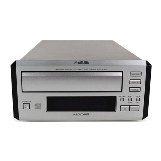
The CRX-E500 is composed of the RX-E400 and the CDC-E500.
This service manual is for the CDC-E500.
For the RX-E400 service manual, please refer to the following publication number:
For the system operation, please refer to the service manual for the RX-E400.
This manual has been provided for the use of authorized YAMAHA Retailers and their service personnel.
It has been assumed that basic service procedures inherent to the industry, and more specifically YAMAHA Products, are already
known and understood by the users, and have therefore not been restated.
WARNING:
IMPORTANT:
The data provided is believed to be accurate and applicable to the unit(s) indicated on the cover. The research, engineering, and
service departments of YAMAHA are continually striving to improve YAMAHA products. Modifications are, therefore, inevitable
and specifications are subject to change without notice or obligation to retrofit. Should any discrepancy appear to exist, please
contact the distributor's Service Division.
WARNING:
IMPORTANT:
I CONTENTS
TO SERVICE PERSONNEL ...................................... 2~3
PREVENTION OF ELECTRO STATIC DISCHARGE ... 3
FRONT PANEL .............................................................. 4
REMOTE CONTROL PANEL ........................................ 4
REAR PANELS .............................................................. 5
SPECIFICATIONS .......................................................... 6
INTERNAL VIEW ........................................................... 6
DISASSEMBLY PROCEDURES ................................... 7
MAIN P.C.B. OPERATION CHECK .............................. 8
CDC-MECHANISM REPAIRING PROCEDURES ... 9~19
STANDARD OPERATION CHART ....................... 20~23
1 0 0 8 1 0
CDC-E500
RX-E400
Failure to follow appropriate service and safety procedures when servicing this product may result in personal
injury, destruction of expensive components, and failure of the product to perform as specified. For these reasons,
we advise all YAMAHA product owners that any service required should be performed by an authorized
YAMAHA Retailer or the appointed service representative.
The presentation or sale of this manual to any individual or firm does not constitute authorization, certification or
recognition of any applicable technical capabilities, or establish a principle-agent relationship of any form.
Static discharges can destroy expensive components. Discharge any static electricity your body may have
accumulated by grounding yourself to the ground buss in the unit (heavy gauge black wires connect to this buss).
Turn the unit OFF during disassembly and part replacement. Recheck all work before you apply power to the unit.
Copyright 2002 YAMAHA CORPORATION
This manual is copyrighted by YAMAHA and may not be copied or
redistributed either in print or electronically without permission.
CRX-E500
SERVICE MANUAL
100809
IMPORTANT NOTICE
TEST MODE ........................................................... 24~25
TROUBLESHOOTING ................................................. 26
IC DATA ................................................................. 27~32
DISPLAY DATA ........................................................... 33
REMOTE CONTROL .................................................... 33
BLOCK DIAGRAM ....................................................... 34
PRINTED CIRCUIT BOARD .................................. 35~37
IC BLOCK ..................................................................... 38
PIN CONNECTION DIAGRAM .................................... 38
SCHEMATIC DIAGRAM .............................................. 39
PARTS LIST ........................................................... 41~48
P.O.Box 1, Hamamatsu, Japan

Advertisement

Table of Contents
loading

Summary of Contents for Yamaha CRX-E500

  • Page 1 This manual has been provided for the use of authorized YAMAHA Retailers and their service personnel. It has been assumed that basic service procedures inherent to the industry, and more specifically YAMAHA Products, are already known and understood by the users, and have therefore not been restated.
  • Page 2: To Service Personnel

    CDC-E500 I TO SERVICE PERSONNEL 1. Critical Components Information AC LEAKAGE WALL EQUIPMENT TESTER OR Components having special characteristics are marked OUTLET UNDER TEST EQUIVALENT s a n d m u s t b e r e p l a c e d w i t h p a r t s h a v i n g specifications equal to those originally installed.
  • Page 3: Prevention Of Electro Static Discharge

    CDC-E500 PROTECTION OF EYES FROM LASER BEAM DURING SERVICING This set employs a laser. Therefore, be sure to carefully follow the instructions below when servicing. 1. Laser Diode Properties • Material : GaAlAs • Wavelength : 780 nm • Emission Duration : Continuous : max.
  • Page 4: Front Panel

    Note: When confirming remote control operation, connect the unit to the RX-E400 by using the system cable. +100 RANDOM PROG MODE TEXT/TIME DISC SKIP TAPE DIRECTION PRESET TUNER PRESET TAPE TAPE REC/PAUSE REC/PAUSE MODE DUBBING START SLEEP DISPLAY VOLUME CRX-E500 V891360...
  • Page 5: Rear Panels

    CDC-E500 I REAR PANELS U, C models A model...
  • Page 6: Specifications

    Gold Color ............. U, C, A models Silver Color ............... U model Accessories of CRX-E500 Remote Control x 1, Indoor FM antenna x 1, AM loop antenna x 1, Audio Pin Cable (2P, 1.0m) x 1, System Control Cable (1P, 1.0m) x 1, Battery (size "UM-3", "R6") x 2...
  • Page 7: Disassembly Procedures

    CDC-E500 I DISASSEMBLY PROCEDURES Top Cover (Remove parts in the order as numbered.) Disconnect the power plug from the AC outlet. 1. Removal of Top Cover a. Remove 4 screws (1) and 4 screws (2) in Fig. 1. b. Lift the Top Cover at the rear and move it rear-ward slantingly.
  • Page 8 CDC-E500 b. Pull out the drawer to open it fully. (Fig. 5) Fig. 5 (Drawer opened fully) I MAIN P.C.B. OPERATION CHECK 1. Remove the CDC Mechanism Unit. 2. Disconnect cable from Connector (CB6) in Fig. 2. At this time, unwind this cable wound around the ferrite core. 3.
  • Page 9 CDC-E500 I CDC-MECHANISM REPAIRING PROCEDURES 1. Explanation of part names and terms. Front/rear: With the mechanism installed normally, the drawer opening direction is to the front. Top/bottom: With the mechanism installed normally, the drawer is visible from the top. Rear: drawer closing direction Slider 1 Arm Stopper B Clamper...
  • Page 10 CDC-E500 2. Opening of Drawer a. Move the lever under the left side face of the mechanism toward the front side first and then toward the rear side. The drawer is unlocked and opens by about 5 to 10cm. (Photo 2) Rear Front lever...
  • Page 11 CDC-E500 4. Removal of Carriage Bevel Gear a. Turn over the drawer removed as described in Procedures 2 and 3 on page 10 and place it with its front facing toward you. (Photo 6) b. Check that the bevel gear located on the left side of the drawer is attached to the drawer.
  • Page 12: A. Remove The Drawer According To Procedures 2 And

    CDC-E500 5. Replacement of Parts 5-1. Replacement of Motor and Belt a. Remove the drawer according to Procedures 2 and 3 on page 10. b. Using tweezers without non-slip section (to avoid scratching) or a fine stick, remove 2 belts. (Photo 9) c.
  • Page 13 CDC-E500 5-2. Replacement of Switches 4 PC board A mounting screws • Switches 6, 7 and 8 a. Remove the drawer according to Procedures 2 and 3 on page 10. b. Turn over the mechanism. c. Remove 4 PC board A mounting screws. (Photo 11) d.
  • Page 14 CDC-E500 Move the arm stopper B d. While moving the arm stopper B in the arrow direction Arm stopper B in this direction. (Photo 14), pull the lever toward you (Photo 13) and lift the arm. (Photo 15) e. Remove 2 screws fixing the arm and while pulling the chassis by the part marked with an arrow, remove the arm.
  • Page 15: Switches 4 And

    CDC-E500 PC board B (with switches 4 and 5 installed) h. While pushing down the point shown in photo 17 with a small tool, like tweezers, move the PC board B to the right to remove it. (Photo 17) i. Unsolder the PC board B and replace the switches. j.
  • Page 16: Photo

    CDC-E500 6. Installation of Carriages Cam RR3 (black) Bevel gear turning direction a. Check that the bevel gear is installed to the drawer. If it Drawer opening direction is not, install it according to Step b of Procedure 4. b. Turn the bevel gear toward the rear (clockwise) until the upper pinion starts to turn.
  • Page 17: Photo

    CDC-E500 Push in the carriage Carriage d. Install the left side of the carriage under the collar of the with fingers. star gear, and then the right side by pushing it with your fingers. (Photo 23) e. Turn the bevel gear toward the rear (clockwise) so that the carriage moves completely forward.
  • Page 18: Photo

    CDC-E500 7. Installation of Drawer a. While holding the drawer in the normal operating, align the lug located on the left side of the drawer to the position where the collar of the arm stopper B is and Drawer lug push it into the chassis.
  • Page 19 CDC-E500 Wall of chassis h. After making sure that the drawer and chassis claws are meshed properly, push in the drawer gradually until it reaches the wall of the chassis. (Photo 31) i. Pull the drawer in its opening direction lightly to check that it is locked.
  • Page 20 CDC-E500 I STANDARD OPERATION CHART DISC 1 open by DISC 1 key “OPEN” appears on the display. Clamp up Carriage change refer to MECH TIMING CHART Clamp down Drawer open DISC 1 play by PLAY key “CLOSE” “CHECK1” appears on the display. Drawer close Clamp up refer to MECH TIMING CHART...
  • Page 21 CDC-E500 Tracking balance ADJ (only OPEN/CLOSE) Focus gain ADJ Tracking gain ADJ ~ TOC read ~ Track No. “1” is searched /MUTE = “L” → “H” (IC201, 71 pin) After searching the beginning, MUTE is cancelled. “0:00” appears on the display. ~ PLAY ~ Search by means of /MUTE = “H”...
  • Page 22 CDC-E500 • CIRCUIT DIAGRAM Pin No. CARRIAGE EXTRA POSITION SW Normal close SW CARRIAGE HOME POSITION SW Normal close SW COMMON CARRIAGE NUMBER SW Normal close SW CARRIAGE NUMBER SW Normal close SW DRAWER OPEN/CLOSE DETECT SW Normal open SW SLIDER FORWARD POSITION SW Normal open SW SLIDER REVERSE POSITION SW...
  • Page 23 CDC-E500 • TIMING CHART...
  • Page 24: Test Mode

    CDC-E500 I TEST MODE POWER Off condition STANDBY/ON Key is pressed while pressing STOP Key and PLAY/PAUSE Key. TEST MODE indication. TEST MODE UP TEST MODE DOWN When pressed, mode is carried out. DISC SKIP Key Test mode number up. Test mode number down.
  • Page 25 CDC-E500 Command Function 16:10 Kick R 10 Kick in the inside direction is repeated every 30msec. 17:10 Kick F 10 Kick in the outside direction is repeated every 30msec. 18:30 Kick R 30 Kick in the inside direction is repeated every 40msec. 19:30 Kick F 30 Kick in the outside direction is repeated every 40msec.
  • Page 26: Troubleshooting

    CDC-E500 I TROUBLESHOOTING <Data cannot be read> <No sound generated, Sound cut during play.> (but time display advances properly) Is disc dirty or Check by using another disc. scratched? MUTING circuit defective. MUTING applied. Microcomputer defective. Outermost TRACKING servo defective. IC202 or IC207 or IC208 Pick-up position FEED servo defective.
  • Page 27 CDC-E500 I IC DATA IC201 : M30622M8A-XXXFP 16 bit µ-COM /WRL/WR /WRH/BHE /BCLK /HLDA M30622M8A-XXXFP /HOLD /ALE /RDY/CLK /CTS /RTS /CLK /CTS /RTS /CLKS /CLK I/O Port Port P0 Port P1 Port P2 Port P3 Port P4 Port P5 Port P6 Internal peripheral Functions System clock generator A-D Converter...
  • Page 28 CDC-E500 IC201 : M30622M8A-XXXFP Pin Description Source Circuit Device Name Program Diagram I/O Contents Logic Other Name Name P96/ANEX1/S – Open P95/ANEX0/CLK4 SQCK O MN35511 serial I/F clock (SQCK) P94/DA1/TB4 LDRCTL O RF amp gain control 2.5V: Normal L: RW P93/DA0/TB3 GCTL O RF amp gain control...
  • Page 29 CDC-E500 Source Circuit Device Name Program Diagram I/O Contents Logic Other Name Name —– P44/CS0 pTest0 O Test port 51 P43/A19 pSysIn SYSCONI System control (In) 52 P42/A18 pSysOut SYSCONO O System control (Out) 53 P41/A17 54 P40/A16 pFEOF FEOF O Feed Off H: OFF L: ON 55 P37/A15...
  • Page 30 CDC-E500 KEY INPUT POWER DISC CHANGE DISC 3 PLAY/PAUSE DISC 2 STOP DISC 1 IC202 : MN35511AL Signal Processor & Controller 58 59 56 19 49 8 7 9 44 46 45 47 48 52 53 67 62 15 14 68 73 72 74 75 13 55 78 80 79 SUBCODE...
  • Page 31 CDC-E500 IC202 : MN35511AL Pin Description Pin No. Name Function BCLK Bit clock output for SR DATA (NC) LRCK L/R identification signal output (NC) SRDATA Serial data output (NC) DVDD1 Power supply for digital circuit (+5) DVSS1 GND for digital circuit Digital, audio, interface output signal MCLK Microprocessor command clock signal input (data latched at leading edge)
  • Page 32 CDC-E500 Pin No. Name Function DSLF Loop filter terminal for DSL PLLF Loop filter terminal for PLL VCOF Loop filter terminal for VCO (+5) AVDD2 Power supply for analog circuit (for AD of DSL, PLL, DA output blocks) (+5) AVSS2 GND for analog circuit (for AD of DSL, PLL, DA output blocks) (GND) EFM signal output...
  • Page 33: Remote Control

    SLEEP DISPLAY – PROG (C) SLEEP – – MODE (D) VOLUME VOLUME – – TEXT/TIME DISPLAY – – DISC SKIP (E) VOLUME – – – – – – – CRX-E500 V891360 – – – V8913600 – – – – –...
  • Page 34 CDC-E500 I BLOCK DIAGRAM CD MECHA. UNIT XL101 PICK UP TP201 IC208 IC207 OUT L TP200 HEAD IC200 CONTROL LINE OUT AN8399SA LD DRIVE IC202 IC208 IC207 MN35511AL VREF OUT R SPC+DAC MUTE CONTROL KICK AN4801SB D4, 5, 10, 11 FCS+ TRK+ DIGITAL OUT...
  • Page 35 CDC-E500 • Semiconductor Location I PRINTED CIRCUIT BOARD (Foil side) Ref. No. Location D200 D201 MAIN (1) P. C. B. (Lead Type Device) D202 D203 MAIN (2) MAIN (2) MAIN (2) D204 D205 D206 IC200 IC201 IC202 IC203 IC207 IC208 MAIN (5) WRITER MAIN (1) P.
  • Page 36 CDC-E500 • Semiconductor Location I PRINTED CIRCUIT BOARD (Foil side) Ref. No. Location MAIN (2) P. C. B. (Lead Type Device) CDC Mechanism Unit CDC Mechanism Unit SYSTEM CONNECTOR MAIN (3) DIGITAL ANALOG MAIN (1) MAIN (1) MAIN (1) MAIN (2) P. C. B. (Surface Mount Device) 28 20 27 7...
  • Page 37 CDC-E500 • Semiconductor Location I PRINTED CIRCUIT BOARD (Foil side) Ref. No. Location IC300 MAIN (3) P. C. B. (Lead Type Device) MAIN (5) P. C. B. (Lead Type Device) DISC 1 /FLRST DISC 2 AC Power DISC 3 Cable DISC 30 31 57 58...
  • Page 38 CDC-E500 I IC BLOCK IC1: AN4801SB-E1 IC6 : M51953BFP IC300: LC75710NE IC203 : S-29190AFJA 4-Channel Power OP-Amp System Driver System Reset CMOS 1kbit EEPROM FL Display Driver Memory array Address decoder Data register Output buffer 5µA SHIFT REGISTER RESET CC/2 CC/2 –...
  • Page 39 CDC-E500 SCHEMATIC DIAGRAM PICK UP MUTING -9.9 -9.9 -9.9 -9.9 SPC WITH DAC LD DRIVE HEAD AMP. ACT. MOTOR DRIVE -9.5 -9.5 CD MECHA. UNIT MUTE CONTROL 10.5 EEP ROM -9.9 10.5 10.5 SYSTEM CONTROL POWER SUPPLY -9.9 -0.2 -9.9 -0.2 AC 9.3 AC 15.2...
  • Page 40: Parts List

    CDC-E500 I WARNING PARTS LIST Components having special characteristics are marked s and must be replaced with parts having specifications equal to those originally I ELECTRICAL PARTS installed. ABBREVIATIONS IN THIS LIST ARE AS FOLLOWS: C.A.EL.CHP : CHIP ALUMI.ELECTROLYTIC CAP L.EMIT : LIGHT EMITTING MODULE C.CE...
  • Page 41 CDC-E500 ! : Note on the Main P.C.B. Of the main P.C.B. part Nos., only the gold (GD) type part Nos. are included in the table. The only different part between the silver (SI) and gold (GD) type parts is the sheet/FL that is attached to the fluorescent character display tube.
  • Page 42 CDC-E500 P.C.B. MAIN Chip Resistors Schm Schm Schm Schm Ref. PART NO. Description Markets Ref. PART NO. Description Markets Ref. PART NO. Description Markets Ref. PART NO. Description Markets C300 US135100 C.CE.CHP 0.1uF HV756220 R.CAR.FP 2.2KΩ 1/4W RD350000 R.CAR.CHP 0Ω 1/10W C301 US135100...
  • Page 43 PW HEAD B-TITE SCREW 3x15-8 MFC2 EP600790 FLAT HEAD B-TITE SCREW MFZN2BL VY712800 PW HEAD B-TITE SCREW 3x8-8 MFNI33 1-11 1-104 ACCESSORIES OF CRX-E500 V8913600 REMOTE CONTROL RC-7060-01-0029 RC-7060-01-0029 200-1 AAX13340 BATTERY COVER BLJYE 60050001 60050001 1-110 V6267000 INDOOR FM ANTENNA 1.4m 1pc...
  • Page 44 CDC-E500 I EXPLODED VIEW (CDC Mechanism Unit) I MECHANICAL PARTS (CDC Mechanism Unit) Ref. PART NO. Description Remarks Markets V7527900 CDC MECHANISM UNIT CMCJ0125 AAX25400 ASS'Y CHASSIS 45 093 4256 AAX25490 DRAWER 2 45 264 3278 AAX25640 ASS'Y HOLDER L 45 093 3141 AAX25650 ASS'Y HOLDER R3B...
  • Page 45 CDC-E500 I GREASE APPLICATION DIAGRAM (CDC Mechanism Unit) G473 948Px2 PG661 SH200CV 10,000CS x 2(Back Side) G473 G473 x 7 948Px2 SH200CV 10,000CS x 2(Back Side) G473 G473 x 2 G473 x 2 G473 948P x 2 E-PASTE G473 x 2 G473 G473 G473...
  • Page 46 CDC-E500 I EXPLODED VIEW (PU Mecha. Unit) Note : Neither the pick-up head nor the spindle motor is available independently because they are factory-adjusted for the optimum level after assembly. If the pick-up head or the spindle motor must be replaced, be sure to replace them together as a unit.
  • Page 47 CDC-E500 I GREASE APPLICATION DIAGRAM (PU Mechanism) Apply the grease Molykote PG-663 (P/No. AAX01170) PG-663 PG-663 PG-663 PG-663...

This manual is also suitable for:

Cdc-e500

Table of Contents