Yamaha CRX-E300 Service Manual
Yamaha mini component system service manual
Hide thumbs
Also See for CRX-E300:
- Owner's manual (192 pages) ,
- Service manual (86 pages) ,
- Instructions for use manual (28 pages)
Table of Contents
Advertisement
QQ
3 7 63 1515 0
CRX-E300/
TE
L 13942296513
I CONTENTS
To Service Personnel .......................................... 2
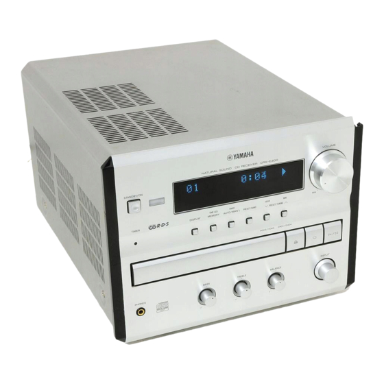
Front Panels ............................................................ 4
Rear Panels .......................................................... 5~6
Specifications ...................................................... 6~7
Internal View ........................................................... 7
TEST MODE
CD TEST MODE
www
.
1 0 0 8 0 5
http://www.xiaoyu163.com
MINI COMPONENT SYSTEM
This manual has been provided for the use of authorized YAMAHA Retailers and their service personnel.
It has been assumed that basic service procedures inherent to the industry, and more specifically YAMAHA Products, are already
known and understood by the users, and have therefore not been restated.
WARNING:
Failure to follow appropriate service and safety procedures when servicing this product may result in personal
injury, destruction of expensive components, and failure of the product to perform as specified. For these reasons,
we advise all YAMAHA product owners that any service required should be performed by an authorized
YAMAHA Retailer or the appointed service representative.
IMPORTANT:
The presentation or sale of this manual to any individual or firm does not constitute authorization, certification or
recognition of any applicable technical capabilities, or establish a principle-agent relationship of any form.
The data provided is believed to be accurate and applicable to the unit(s) indicated on the cover. The research, engineering, and
service departments of YAMAHA are continually striving to improve YAMAHA products. Modifications are, therefore, inevitable
and specifications are subject to change without notice or obligation to retrofit. Should any discrepancy appear to exist, please
contact the distributor's Service Division.
WARNING:
Static discharges can destroy expensive components. Discharge any static electricity your body may have
accumulated by grounding yourself to the ground buss in the unit (heavy gauge black wires connect to this buss).
IMPORTANT:
Turn the unit OFF during disassembly and part replacement. Recheck all work before you apply power to the unit.
........... 8~10
x
ao
u163
y
i
http://www.xiaoyu163.com
2 9
8
SERVICE MANUAL
IMPORTANT NOTICE
Q Q
3
6 7
1 3
1 5
CD ERROR MESSAGE
AMP ADJUSTMENTS
Ic Data ................................................................. 28~37
Display Data ........................................................... 38
Block Diagram ................................................. 39~40
Printed Circuit Board .................................. 41~46
Schematic Diagram ........................................ 47~50
REMOTE CONTROL .................................................... 51
11
PARTS LIST ........................................................... 52~68
System Control .............................................. 69~83
12~15
Nx-E300 ....................................................................... 84
16~17
Parts List For Carbon Resistors ................................ 85
18~21
co
.
9 4
2 8
NX-E300
0 5
8
2 9
9 4
2 8
m
P.O.Box 1, Hamamatsu, Japan
9 9
9 9
22~25
26~27
Advertisement
Table of Contents
Troubleshooting

Related Manuals for Yamaha CRX-E300


Summary of Contents for Yamaha CRX-E300
- Page 1 This manual has been provided for the use of authorized YAMAHA Retailers and their service personnel. It has been assumed that basic service procedures inherent to the industry, and more specifically YAMAHA Products, are already known and understood by the users, and have therefore not been restated.
-
Page 2: To Service Personnel
CRX-E300 3 7 63 1515 0 AC LEAKAGE I TO SERVICE PERSONNEL WALL EQUIPMENT TESTER OR OUTLET UNDER TEST EQUIVALENT 1. Critical Components Information Components having special characteristics are marked s a n d m u s t b e r e p l a c e d w i t h p a r t s h a v i n g specifications equal to those originally installed. -
Page 3: Prevention Of Electro Static Discharge
CRX-E300 3 7 63 1515 0 Laser Diode Properties • Material : GaAlAs Optical Pick-up • Wavelength : 780 nm • Emission Duration : Continuous : max. 44.6 µW* • Laser Output * This output is the value measured at a distance of about 200 mm from the objective lens surface on the Optical Pick-up Block. -
Page 4: Front Panels
CRX-E300 3 7 63 1515 0 Grounding for electrostatic breakdown prevention 1. Human body grounding Use the antistatic wrist strap to discharge the static electricity from your body. Anti-static wrist strip 2. Work table grounding 1MΩ Put a conductive material (sheet) or steel sheet on the area where the optical pickup is placed and ground the sheet. -
Page 5: Rear Panels
CRX-E300 3 7 63 1515 0 I REAR PANELS U, C models A model B model G model L 13942296513 R model K model u163 http://www.xiaoyu163.com... -
Page 6: Specifications
CRX-E300 3 7 63 1515 0 J model I FM Section / Tuning Range / [U, C models] ........... 87.5 to 107.9 MHz [A, B, G models] ........... 87.50 to 108.00 MHz [R, K models] ...... 87.5 to 108.0 / 87.50 to 108.00 MHz [J model] ............. - Page 7 CRX-E300 3 7 63 1515 0 I SPEAKER Section / (NX-E300) Type / ......... 2 Way Bass-reflex Magnetic Shielding Type Driver / Woofer ........... 11cm (4-1/2") Cone Type Tweeter ............. 2.5cm (1") Dome Type Frequency Response / ................60 Hz to 28 kHz Impedance / ....................
-
Page 8: Disassembly Procedures
CRX-E300 3 7 63 1515 0 I DISASSEMBLY PROCEDURES (Remove parts in the order as numbered.) Disconnect the power plug from the AC outlet. a. Remove 4 screws (1) and 5 screws (2) in Fig. 1. b. Lift the Top Cover at the rear and move it rear-ward slantingly. - Page 9 CRX-E300 3 7 63 1515 0 a. Disconnect cables from Connectors (CB417, CB416, CB306, CB412) in Fig. 3. b. Remove the cap (6) from the Digital Output Terminal in Fig. 4. c. Remove 3 screws (7), 1 screw (8) and 2 screws (9) in Fig.
- Page 10 CRX-E300 3 7 63 1515 0 a. Remove 2 screws (F) in Fig. 7. b. Remove the Pick-up Cable in Fig. 7. c. Remove 4 screws (G) and then remove the Drive Unit in Fig. 7. d. Remove the Gear A in Fig. 8.
- Page 11 CRX-E300 3 7 63 1515 0 I CD MECHANISM UNIT OPERATION CHECK / 1. Disconnect the power plug from the AC outlet. 2. Remove the top cover. 3. Remove the front panel unit. 4. Remove the tuner. 5. Remove the MAIN (1) P.C.B.
-
Page 12: Test Mode
CRX-E300 3 7 63 1515 0 I TEST MODE POWER Off condition STANDBY/ON Key is pressed while pressing DISPLAY Key and AUTO/MAN'L Key. TEST MODE indication. When present mode is TEST MODE DOWN TEST MODE UP carried out. PRESET/TUNING... - Page 13 CRX-E300 3 7 63 1515 0 L 13942296513 TIMER PRESET STEREO AUTO RT CT REP S F PROG RANDOM TIMER SLEEP MEMORY TUNED PTY HOLD TITLE ARTIST TRACK CD-TEXT TIMER TIMER u163 http://www.xiaoyu163.com...
- Page 14 CRX-E300 3 7 63 1515 0 (*1) DESTINATION R (AM9k/FM:50k) R (AM10k/FM100k) Display R10k B, G U, C (*2) Contents of indication change by the microcomputer software. CAUTION : When executing Test mode No. 2 RAM CLEAR, be sure to write down the preset memory contents of the tuner, using a table like the one shown below.
- Page 15 CRX-E300 3 7 63 1515 0 DESTINATION R (AM9k/FM:50k) R (AM10k/FM100k) Display R10k B, G U, C Preset group FM (MHz) 83.0 82.1 76.0 84.0 86.0 90.0 78.0 88.0 1080 1404 1611 1350 1440 AM (kHz) L 13942296513 u163...
-
Page 16: Cd Test Mode
CRX-E300 3 7 63 1515 0 I CD TEST MODE When STANDBY mode, press the ”STANDBY/ON” key while pressing the ”STOP” key and the ”PLAY/PAUSE” key simultaneously. An opening message is displayed for a few seconds and then the TEST MODE is activated. - Page 17 CRX-E300 3 7 63 1515 0 ” ” ” ” ” ” Open/Close L 13942296513 Auto Adj-1 Auto Adj-2 Auto Adj-3 Traverse Rev Traverse Fwd Traverse Stp SP Accel SP Brake SP Servo On SP Servo Off SP Stop Focus Search Trk&Trv Off...
-
Page 18: Cd Standard Operation Chart
CRX-E300 3 7 63 1515 0 I CD STANDARD OPERATION CHART POWER ON If a disc is not loaded, “No Disc” appears on the FL display. Press OPEN/CLOSE key. “01 OPEN” appears on the FL display. “TRV” signal is output until detection of LIMIT switch. - Page 19 CRX-E300 3 7 63 1515 0 “ ” “ ” “ ” “ ” L 13942296513 “ ” “ ” “ ” “ ” “ ” u163 http://www.xiaoyu163.com...
- Page 20 CRX-E300 3 7 63 1515 0 Tracking gain rough ADJ Tracking balance ADJ (only tray OPEN/CLOSE) Focus balance ADJ Focus gain ADJ Tracking gain ADJ * TOC READ ~ * Data retrieval cycle ~ TRACK NO. “1” is searched.
- Page 21 CRX-E300 3 7 63 1515 0 “ ” “ ” “ ” “ ” “ ” L 13942296513 “ ” “ ” “ ” “ ” “ ” “ ” “ ” “ ” u163 http://www.xiaoyu163.com...
- Page 22 CRX-E300 3 7 63 1515 0 I CD ERROR MESSAGE (1) If a CD error occurs, an error message can be displayed by holding down the “MEMORY” key and pressing the “PRESET/BAND” key. (2) Shown below is an example of display. (“E-73” as an example) (3) Listed in the table below are error messages.
- Page 23 CRX-E300 3 7 63 1515 0 ” ” ” ” L 13942296513 X0 , X1 , 73 AC , AD u163 http://www.xiaoyu163.com...
- Page 24 CRX-E300 3 7 63 1515 0 c) Operates as if no disc loaded. (although loaded) 2) Troubleshooting System Malfunctions a) Tray fails to come out/go in. Does tray Poor tray loading load properly? Poor mechanism Tray starts to operation move but stops.
- Page 25 CRX-E300 3 7 63 1515 0 “ ” L 13942296513 u163 http://www.xiaoyu163.com...
- Page 26 CRX-E300 3 7 63 1515 0 I AMP ADJUSTMENTS Confirmation of Idling Current 1) No signal applied. 2) Non-loaded condition. 3) Aging is not neccessary. Item Test Point Rating (DC) Note R471 If the measured voltage exceeds 5mV, cut the lead wire of R440 (L...
- Page 27 CRX-E300 3 7 63 1515 0 0.1mV ~ 5mV (DC) R440 (L ch) R445 (R ch) R471 (L ch) R474 (R ch) L 13942296513 Q413 R474 R445 Q412 R471 R440 u163 http://www.xiaoyu163.com...
- Page 28 CRX-E300 3 7 63 1515 0 I IC DATA IC301: BU2092 (INPUT P.C.B.) Serial In / Parallel Out Driver DATA 1 CLOCK 1 Control 4051 2C Circuit LATCH 1 4051 2B TUNER MUTE 4051 2A MUTE A 4051 1/2...
- Page 29 CRX-E300 3 7 63 1515 0 IC302: BU2092 (INPUT P.C.B.) Serial In / Parallel Out Driver DATA 2 CLOCK 2 Control Circuit LATCH 2 STAN FEOF DMUTE MUTE Name Function DATA 2 CLOCK 2 LATCH 2 STAN (CD) Motor Driver Mute...
- Page 30 CRX-E300 3 7 63 1515 0 IC303: TC74HC4051AP (INPUT P.C.B.) Analog Multiplexer/Demultiplexer INHIBIT LEVEL BINARY TO 1-OF-8 CONVERTER DECODER WITH INHIBIT INPUT STATES “ON” CHANNEL (S) INHIBIT NONE Name Function STATION IN (TUNER) [0: Station available] Power Amp. excess current DC voltage detect IN...
- Page 31 CRX-E300 3 7 63 1515 0 IC201: M30217MAAFP (OPERATION P.C.B.) P67/FLD7 P24/FLD36 P66/FLD6 P25/FLD37 P65/FLD5 P26/FLD38 P64/FLD4 P27/FLD39 P63/FLD3 P30/FLD40 P62/FLD2 P31/FLD41 P61/FLD1 P32/FLD42 P60/FLD0 P33/FLD43 P34/FLD44 P107/AN7 P35/FLD45 P106/AN6 P36/FLD46 P105/AN5 P37/FLD47 P104/AN4 P40/FLD48 P103/AN3 P41/FLD49 P102/AN2 P42/FLD50...
- Page 32 CRX-E300 3 7 63 1515 0 IC201: M30217MAAFP (OPERATION P.C.B.) PORT Name IN/OUT Function CCB (LC72131 / LC72720 / LC78211) CE OUT CLK1 LC72131 / LC72720 / LC78211 CLK OUT RxD1 LC72131 / LC72720 DATA IN TxD1 LC72131 / LC72720 / LC78211 DATA OUT...
- Page 33 CRX-E300 3 7 63 1515 0 IC201: M30217MAAFP (OPERATION P.C.B.) PORT Name IN/OUT Function SEG25 POD O SEGMENT 25 (P25) SEG26 POD O SEGMENT 26 (P26) SEG27 POD O SEGMENT 27 (P27) SEG28 POD O SEGMENT 28 (P28) SEG29...
- Page 34 CRX-E300 3 7 63 1515 0 IC202: TC74HC4051AF (OPERATION P.C.B.) Analog Multiplexer/Demultiplexer INHIBIT INPUT STATES "ON" CHANNNEL LEVEL BINARY TO 1-OF-8 INHIBIT CONVERTER DECODER WITH INHIBIT NONE Name Function [Pull Up → VREF at 10kΩ] Destination select input (Input)
- Page 35 CRX-E300 3 7 63 1515 0 IC406: MN35511AL (CD P.C.B.) Signal Processor & Controller 58 59 56 19 49 8 7 9 44 46 45 47 48 52 53 67 62 15 14 68 73 72 74 75 13 55...
- Page 36 CRX-E300 3 7 63 1515 0 IC406: MN35511AL (CD P.C.B.) Signal Processor & Controller Pin No. Name Function BCLK Bit clock output for SR DATA (NC) LRCK L/R identification signal output (NC) SRDATA Serial data output (NC) DVDD1 Power supply for digital circuit...
- Page 37 CRX-E300 3 7 63 1515 0 IC406: MN35511AL (CD P.C.B.) Signal Processor & Controller Pin No. Name Function DSLF Loop filter terminal for DSL PLLF Loop filter terminal for PLL VCOF Loop filter terminal for VCO (+5) AVDD2 Power supply for analog circuit (for AD of DSL, PLL, DA output blocks)
- Page 38 CRX-E300 3 7 63 1515 0 G V201 : 16-BT-84GN (V6253100) PATTERN AREA ™ G PIN CONNECTION Pin No. Connection Pin No. Connection Note : 1) F1, F2 ..Filament 2) NP ..No pin 3) IC ..Internal connection (IC pin should be electrically open on the PC board) 4) Pin No.
-
Page 39: Block Diagram
CRX-E300 3 7 6 3 1 5 1 5 0 I BLOCK DIAGRAM (1/2) OPERATION See page 48 Q201, 203 Q202 BACKUP CAPACITOR FOR TIMER ONLY IC202 C217 EXT-IN U, C, A, B, G, K, J models only RY402,... - Page 40 CRX-E300 3 7 6 3 1 5 1 5 0 I BLOCK DIAGRAM (2/2) See page 49 +A5V +D5V +M5V IC404 +12V IC406 -12V CB412 EFMGND Q400 BLKCK /FLOCK STAT /TLOCK /CLDCK /MNRST SUBQ /MLD SQCK IC410 1 3 9 4 2 2 9 6 5 1 3...
-
Page 41: Printed Circuit Board
CRX-E300 3 7 6 3 1 5 1 5 0 I PRINTED CIRCUIT BOARD (Foil side) INPUT (3) INPUT (1) P. C. B. -12V +12V VR-DN (Lead Type Device) VR-UP T-FB-R TAPE • Semiconductor Location Ref. No. Location D301... - Page 42 CRX-E300 3 7 6 3 1 5 1 5 0 • Semiconductor Location I PRINTED CIRCUIT BOARD (Foil side) Ref. No. Location D751 MAIN (1) IC751 INPUT (3) P. C. B. (Lead Type Device) IC752 VOLUME INPUT (1) -12V...
- Page 43 CRX-E300 3 7 6 3 1 5 1 5 0 I PRINTED CIRCUIT BOARD (Foil side) INPUT (1) INPUT (1) MAIN (1) OPERATION P. C. B. (Lead Type Device) INPUT (2) STANDBY/ 22 21 1 3 9 4 2 2 9 6 5 1 3...
- Page 44 CRX-E300 3 7 6 3 1 5 1 5 0 I PRINTED CIRCUIT BOARD (Foil side) CD Mechanism Unit (Lead Type Device) CD P. C. B. MAIN (1) (Surface Mount Device) CD P. C. B. INPUT (1) DATA-2 MCLK...
- Page 45 CRX-E300 3 7 6 3 1 5 1 5 0 • Semiconductor Location I PRINTED CIRCUIT BOARD (Foil side) Circuit No. U, C A, B R, K C439 C454, 463 Ref. No. Location C460, 461 D401 CB408,411 MAIN (6) P. C. B.
- Page 46 CRX-E300 3 7 6 3 1 5 1 5 0 I PRINTED CIRCUIT BOARD (Foil side) Circuit No. U, C A, B R, K C460, 461 CB401, 402 F400 SW400 W400~405 MAIN (2), (3), (4) P. C. B. (Lead Type Device) MAIN (5) P.
-
Page 47: Schematic Diagram
CRX-E300 SCHEMATIC DIAGRAM (INPUT) # All voltage are measured with a 10MΩ/V DC electric volt meter. # Components having special characteristics are marked s and must be replaced with parts having specifications equal to those originally installed. IC303: TC74HC4051AP # Schematic diagram is subject to change without notice. - Page 48 CRX-E300 SCHEMATIC DIAGRAM (OPERATION) 3 7 6 3 1 5 1 5 0 FLUORESCENT DISPLAY Point 1 Pin 13 of IC201 Point 2 Pin 11 of IC201 -25.3 -30.3 Point 3 emitter of Q203 and collector of Q201 µ-COM -30.1...
- Page 49 CRX-E300 SCHEMATIC DIAGRAM (CD) IC407: AN8785SB 3 7 6 3 1 5 1 5 0 5-Channel Power OP-Amp System Driver Point 1 Pin 59 of IC406 Thermal Protection Circuit Standby Band gap Reset Circuit 1.25V VREF to CD Page 50...
- Page 50 CRX-E300 SCHEMATIC DIAGRAM (MAIN) # All voltage are measured with a 10MΩ/V DC electric volt meter. # Components having special characteristics are marked s and must be replaced with parts having specifications equal to those originally installed. # Schematic diagram is subject to change without notice.
-
Page 51: Remote Control
CRX-E300 3 7 63 1515 0 REMOTE CONTROL I SCHEMATIC DIAGRAM KI/O6 KI/O5 KI/O7 KI/O4 KI/O3 KI/O2 KI/O1 2SD1781KR 220Ω DC3V B1 KI/O0 XOUT 455kHz 47µF/16 RESET 0.1µF L 13942296513 U, C, A, R, K, J models B, G models... -
Page 52: Parts List
CRX-E300 PARTS LIST 3 7 63 1515 0 I ELECTRICAL PARTS I WARNING Components having special characteristics are marked s and must be replaced with parts having specifications equal to those originally installed. Carbon resistors (1/6W or 1/4W) are not included in the ELECTRICAL PARTS List. For the parts No. of the carbon resistors, refer to last page. - Page 53 CRX-E300 3 7 63 1515 0 P.C.B. INPUT L 13942296513 u163 ✻ New Parts http://www.xiaoyu163.com...
- Page 54 CRX-E300 3 7 63 1515 0 P.C.B. INPUT L 13942296513 u163 ✻ New Parts http://www.xiaoyu163.com...
- Page 55 CRX-E300 3 7 63 1515 0 P.C.B. INPUT & P.C.B. OPERATION L 13942296513 u163 ✻ New Parts http://www.xiaoyu163.com...
- Page 56 CRX-E300 3 7 63 1515 0 P.C.B. OPERATION & P.C.B. CD L 13942296513 u163 ✻ New Parts http://www.xiaoyu163.com...
- Page 57 CRX-E300 3 7 63 1515 0 P.C.B. CD L 13942296513 u163 ✻ New Parts http://www.xiaoyu163.com...
- Page 58 CRX-E300 3 7 63 1515 0 P.C.B. CD & P.C.B. MAIN L 13942296513 u163 ✻ New Parts http://www.xiaoyu163.com...
- Page 59 CRX-E300 3 7 63 1515 0 P.C.B. MAIN L 13942296513 u163 ✻ New Parts http://www.xiaoyu163.com...
- Page 60 CRX-E300 3 7 63 1515 0 P.C.B. MAIN L 13942296513 u163 ✻ New Parts http://www.xiaoyu163.com...
- Page 61 CRX-E300 3 7 63 1515 0 P.C.B. MAIN L 13942296513 u163 ✻ New Parts http://www.xiaoyu163.com...
- Page 62 CRX-E300 3 7 63 1515 0 P.C.B. MAIN L 13942296513 ✻ New Parts ! : Note on the Operation P.C.B. Of the Operation PCB part Nos., only the gold (GD) type part Nos. are included in the table. The only different part between the silver (SI) and gold (GD) type parts is the sheet/FL that is attached to the fluorescent character display tube.
- Page 63 CRX-E300 3 7 63 1515 0 Chip Resistors L 13942296513 u163 ✻ New Parts http://www.xiaoyu163.com...
- Page 64 CRX-E300 3 7 63 1515 0 I EXPLODED VIEW 1-10 1-13 1-11 1-110 1-111 1-104 1-111 1-103 1-105 1-12 1-110 R,K version 1-102 13 (2, 3, 4) 1-106 1-103 1-107 13 (6) 2-112 L 13942296513 1-101 K version 2-105...
- Page 65 CRX-E300 3 7 6 3 1 5 1 5 0 I MECHANICAL PARTS 1 3 9 4 2 2 9 6 5 1 3 w w w u 1 6 3 ✻ New Parts ✻ New Parts http://www.xiaoyu163.com...
- Page 66 CRX-E300 3 7 6 3 1 5 1 5 0 ! : Note on the Operation P.C.B. I EXPLODED VIEW (CD Mechanism Unit) Of the Operation PCB part Nos., only the gold (GD) type part Nos. are included in the table.
- Page 67 CRX-E300 3 7 63 1515 0 I MECHANICAL PARTS (CD Mechanism Unit) L 13942296513 u163 ✻ New Parts http://www.xiaoyu163.com...
- Page 68 CRX-E300 3 7 63 1515 0 I EXPLODED VIEW (Drive Unit) Note: The parts marked with an asterisk ( ) are not available separately. Cover L 13942296513 u163 ✻ New Parts http://www.xiaoyu163.com...
-
Page 69: System Control
CRX-E300 3 7 63 1515 0 SYSTEM CONTROL / Features • One bus line controls all the units. • Units are connected in series, using monaural mini jacks. • Units can be connected in any order Description of Operation... - Page 70 CRX-E300 3 7 63 1515 0 Description of main system operation 1) POWER ON/OFF processing [(1) to (4)] • The power cord of each unit is connected to the AC outlet in series and switched on and off through the CRX relay.
- Page 71 CRX-E300 3 7 63 1515 0 5) CD TEXT compatible When recording the contents of the CD TEXT compatible CD into an MD in the SYNCHRONOUS or EDIT mode, the text data is recorded as well although limited up to 127 characters of the track name only for SYNCHRONOUS recording, and names of the disc, artist and track for EDIT recording.
- Page 72 CRX-E300 3 7 63 1515 0 (1) POWER ON PROCESSING (CRX) When the power is turned on at the CRX, the relay of the AC outlet is turned on to supply power to each unit. Each unit informs the CRX of its status when started (secondary connection status).
- Page 73 CRX-E300 3 7 63 1515 0 L 13942296513 u163 http://www.xiaoyu163.com...
- Page 74 CRX-E300 3 7 63 1515 0 (4) POWER OFF processing (except CRX) When the power is turned off at a unit other than the CRX, the unit informs the CRX of the status when the power off processing has been completed.
- Page 75 CRX-E300 3 7 63 1515 0 ≠ ≠ L 13942296513 ≠ ≠ ≠ u163 http://www.xiaoyu163.com...
- Page 76 CRX-E300 3 7 63 1515 0 (7) TIMER PLAY Timer play by built-in timer Remarks Timer time reached This function is Execution of ignored when no PLAY unit is (1) Power ON processing connected. (CRX) Function selection [FUNC_CD] [FUNC_MD]...
- Page 77 CRX-E300 3 7 63 1515 0 L 13942296513 u163 http://www.xiaoyu163.com...
- Page 78 CRX-E300 3 7 63 1515 0 (9) AUTO POWER ON Function to turn ON the power without using the power switch on the unit other than the CRX Remarks Auto power ON applicable key Auto power ON applicable key...
- Page 79 CRX-E300 3 7 63 1515 0 L 13942296513 → → → → → → u163 http://www.xiaoyu163.com...
- Page 80 CRX-E300 3 7 63 1515 0 Function CODE CODE CODE CD_STOP Remote control CD_PLAY/PAUSE CD_EJECT CD_SKIP+ CD_SKIP- SEARCH+ SEARCH- SEACH_END CD_RANDOM CD_TIME CD_PRG CD_RPT TAPE PEAK SEARCH CD_0 CD_1 CD_2 CD_3 CD_4 CD_5 CD_6 CD_7 CD_8 CD_9 CD_10 MD_STOP...
- Page 81 CRX-E300 3 7 63 1515 0 L 13942296513 u163 http://www.xiaoyu163.com...
- Page 82 CRX-E300 3 7 63 1515 0 Reception status of operation switches during recording (*=AUX or TUNER) EDIT or EDIT(TR-1) RECORDING SYNCHRONOUS or MANUAL RECORDING Unit C→T C→M M→T T→M C→T C→M M→T T→M C→T,M *→M *→T *→T,M POWER FUNCTION...
- Page 83 CRX-E300 3 7 63 1515 0 (*=AUX or TUNER) C→T C→M M→T T→M C→T C→M M→T T→M C→T,M *→M *→T,M *→T • • • L 13942296513 u163 http://www.xiaoyu163.com...
- Page 84 CRX-E300 3 7 63 1515 0 NX-E300 30 x2 1-12 L 13942296513 TWEETER (XW275A00) 2.7Ω/5W 3.3µF/63V WOOFER INPUT (XZ668A00) 1.0mH u163 ✻ New Parts http://www.xiaoyu163.com...
-
Page 85: Parts List For Carbon Resistors
CRX-E300 3 7 63 1515 0 Parts List for Carbon Resistors Value 1/4W Type Part No. 1/6W Type Part No. Value 1/4W Type Part No. 1/6W Type Part No. 1.0 Ω 3100 3100 10 kΩ 7100 7100 HJ35 HF85... - Page 86 3 7 63 1515 0 CRX-E300 L 13942296513 u163 http://www.xiaoyu163.com...
Need help?
Do you have a question about the CRX-E300 and is the answer not in the manual?
Questions and answers