Table of Contents
Advertisement
MICRO COMPONENT SYSTEM
QQ
3 7 63 1515 0
COMPACT DISC RECEIVER/SPEAKER SYSTEM
CRX-E320/
TE
L 13942296513
I CONTENTS
TO SERVICE PERSONNEL ...................................... 2-3
SYSTEM COMPOSITION / システム構成 ..................... 4
FRONT PANEL .............................................................. 5
REMOTE CONTROL PANELS ...................................... 5
REAR PANELS .............................................................. 6
SPECIFICATIONS / 参考仕様 ........................................ 7
INTERNAL VIEW ........................................................... 7
DISASSEMBLY PROCEDURES / 分解手順 ............ 8-10
TEST MODE / テストモード .................................. 11-12
www
.
1 0 1 0 4 9
http://www.xiaoyu163.com
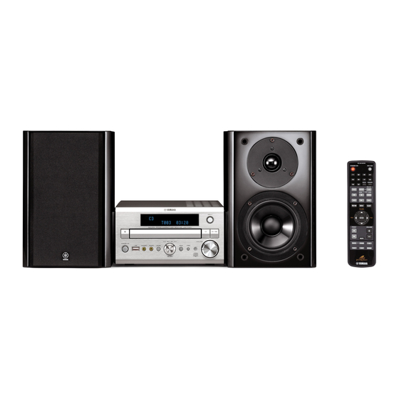
The MCR-E320 consists of the CRX-E320 and the NX-E700.
MCR-E320 は CRX-E320 および NX-E700 で構成されています。
This manual has been provided for the use of authorized YAMAHA Retailers and their service personnel.
It has been assumed that basic service procedures inherent to the industry, and more specifically YAMAHA Products, are already
known and understood by the users, and have therefore not been restated.
WARNING:
Failure to follow appropriate service and safety procedures when servicing this product may result in personal
injury, destruction of expensive components, and failure of the product to perform as specified. For these reasons,
we advise all YAMAHA product owners that any service required should be performed by an authorized
YAMAHA Retailer or the appointed service representative.
IMPORTANT:
The presentation or sale of this manual to any individual or firm does not constitute authorization, certification or
recognition of any applicable technical capabilities, or establish a principle-agent relationship of any form.
The data provided is believed to be accurate and applicable to the unit(s) indicated on the cover. The research, engineering, and
service departments of YAMAHA are continually striving to improve YAMAHA products. Modifications are, therefore, inevitable
and specifications are subject to change without notice or obligation to retrofit. Should any discrepancy appear to exist, please
contact the distributor's Service Division.
WARNING:
Static discharges can destroy expensive components. Discharge any static electricity your body may have
accumulated by grounding yourself to the ground buss in the unit (heavy gauge black wires connect to this buss).
IMPORTANT:
Turn the unit OFF during disassembly and part replacement. Recheck all work before you apply power to the unit.
x
ao
u163
y
i
2007
This manual is copyrighted by YAMAHA and may not be copied or
redistributed either in print or electronically without permission.
http://www.xiaoyu163.com
MCR-E320
2 9
8
NX-E700
SERVICE MANUAL
IMPORTANT NOTICE
Q Q
3
6 7
1 3
1 5
SERVICE MODE / サービスモード ....................... 13-14
FACTORY MODE / ファクトリーモード ............... 13-14
DISPLAY DATA ........................................................... 15
BLOCK DIAGRAM ....................................................... 16
WIRING DIAGRAM ...................................................... 17
PRINTED CIRCUIT BOARDS ................................ 18-23
SCHEMATIC DIAGRAMS ...................................... 24-27
PIN CONNECTION DIAGRAMS .................................. 28
REPLACEMENT PARTS LIST .............................. 29-32
REMOTE CONTROL .............................................. 32-33
co
.
All rights reserved.
9 4
2 8
0 5
8
2 9
9 4
2 8
m
P.O.Box 1, Hamamatsu, Japan
9 9
9 9
'07.06
Advertisement
Table of Contents

Related Manuals for Yamaha MCR-E320


Summary of Contents for Yamaha MCR-E320
-
Page 1: Table Of Contents
This manual has been provided for the use of authorized YAMAHA Retailers and their service personnel. It has been assumed that basic service procedures inherent to the industry, and more specifically YAMAHA Products, are already known and understood by the users, and have therefore not been restated. -
Page 2: To Service Personnel
http://www.xiaoyu163.com CRX-E320/NX-E700 3 7 63 1515 0 I TO SERVICE PERSONNEL AC LEAKAGE WALL EQUIPMENT TESTER OR 1. Critical Components Information OUTLET UNDER TEST EQUIVALENT Components having special characteristics are marked s and must be replaced with parts having specifications equal to those originally installed. - Page 3 http://www.xiaoyu163.com CRX-E320/NX-E700 3 7 63 1515 0 Laser Emitting conditions: 1) When the top cover is removed, and the STANDBY/ON SW is turned to the “ON” position, the laser component will emit a beam for several seconds to detect if a disc is present. During this time (5-10 sec.) the laser may radiate through the lens of the laser pick-up unit.
-
Page 4: Prevention Of Electrostatic Discharge
Conductive material take care not to let your clothes touch the optical pick-up. (sheet) or steel sheet I SYSTEM COMPOSITION / システム構成 The MCR-E320 consists of the CRX-E320 and the NX-E700. MCR-E320 は CRX-E320 および NX-E700 で構成されています。 NX-E700 NX-E700 CRX-E320 u163 http://www.xiaoyu163.com... -
Page 5: Front Panel
http://www.xiaoyu163.com 3 7 63 1515 0 L 13942296513 u163 http://www.xiaoyu163.com... -
Page 6: Rear Panels
http://www.xiaoyu163.com 3 7 63 1515 0 L 13942296513 u163 http://www.xiaoyu163.com... -
Page 7: Specifications / 参考仕様
http://www.xiaoyu163.com CRX-E320/NX-E700 3 7 6 3 1 5 1 5 0 I SPECIFICATIONS / 参考仕様 CRX-E320 NX-E700 I Player Section / プレーヤー部 • DIMENSIONS / 寸法図 Type / 型式 ......... 2-way bass reflex speaker system/ Playback System / 再生システム Magnetic shielding type CRX-E320 NX-E700 .................. -
Page 8: Disassembly Procedures / 分解手順
http://www.xiaoyu163.com CRX-E320/NX-E700 3 7 6 3 1 5 1 5 0 I DISASSEMBLY PROCEDURES / 分解手順 CRX-E320 • How to manually eject the tray / 手動でトレイを開く方法 a. Turn the unit bottom up. • Remove parts in disassembly order as numbered. ・... - Page 9 http://www.xiaoyu163.com CRX-E320/NX-E700 3 7 63 1515 0 Power cable 電源コード CD mechanism unit CDメカユニット CONNECTOR P.C.B. CN91 CN32 FRONT/SMPS (3) P.C.B. CN93 Tuner module チューナーモジュール CN31 Shield case CN45 シールドケース CN92 MAIN (2) P.C.B. MAIN (1) P.C.B. Heat sink L 13942296513 ヒートシンク...
- Page 10 http://www.xiaoyu163.com CRX-E320/NX-E700 3 7 63 1515 0 7. オプティカルピックアップユニットの外し方 7. Removal of Optical Pick-up Unit a. E のネジ4本を外し、ドライブユニットを取り外しま a. Remove 4 screws (E) and then remove the drive unit. (Fig. 5) す。 (Fig. 5) b. カード電線、コネクターASSYを外します。 (Fig. 5) b. Remove flexible flat cable and connector ass’y. (Fig. 5) c.
-
Page 11: Test Mode / テストモード
http://www.xiaoyu163.com CRX-E320/NX-E700 3 7 63 1515 0 I TEST MODE Operation and FIP display of the CD mechanism unit are checked. • Starting Test Mode a. Connect the power cable to the AC power outlet. b. Press the “STANDBY/ON” key while simultaneously pressing “ ”... - Page 12 http://www.xiaoyu163.com CRX-E320/NX-E700 3 7 63 1515 0 I テストモード CDメカユニットの動作チェックおよび表示器のチェックを行います。 ・ テストモードの起動 a. 電源コードをACコンセントに接続します。 b. 同時に本機の “ ” ( PLAY/PAUSE) キーと “ ” ( STOP) キーを押しながら、 “STANDBY/ON” キーを押します。 W W W W W D D D D D A A A A A c.
-
Page 13: Service Mode / サービスモード
http://www.xiaoyu163.com CRX-E320/NX-E700 3 7 63 1515 0 I SERVICE MODE The firmware versions of the main microprocessor, DSP and USB microprocessors are displayed. • Starting Service Mode a. Connect the power cable to the AC power outlet. b. To open the tray, press the “F”(EJECT) key of the main unit or “OPEN/CLOSE” key of the remote control. c. - Page 14 http://www.xiaoyu163.com CRX-E320/NX-E700 3 7 63 1515 0 I サービスモード メインマイコン、DSP、USBマイコンのファームウェアバージョンを表示します。 ・ サービスモードの起動 a. 電源コードをACコンセントに接続します。 b. 本機の “ ” ( イジェクト) キーまたはリモコンの “OPEN/CLOSE” キーを押し、トレイを引き出します。 F F F F F c. トレイを引き出した状態で、本機の “ ” ( STOP) キーを約4秒間押し続けます。 A A A A A サービスモードが起動します。...
-
Page 15: Display Data
http://www.xiaoyu163.com CRX-E320/NX-E700 3 7 6 3 1 5 1 5 0 I DISPLAY DATA G FIP1: HCA-17SM03T (FRONT/SMPS P.C.B.) G ANODE CONNECTION COM1 COM2 COM3 – COM15 COM16 COM17 COM1 COM2 COM3 – COM15 COM16 COM17 – – PATTERN AREA SEGB1 SEGA1 SEGB2... -
Page 16: Block Diagram
http://www.xiaoyu163.com CRX-E320/NX-E700 3 7 6 3 1 5 1 5 0 I BLOCK DIAGRAM +3.3V 2,14,23 +8VM +3.3V +22VA +VREF +1.5V IC26 -22VA AC_IN FOCUS+/- 15,16 +1.5V CD MECHANISM UNIT IC29 +VREF +12V KSL-2130CCMZ TRACK+/- 17,18 MOTOR DRIVE TA2125 -12V 19,20 SLED+/- +8VM... -
Page 17: Wiring Diagram
http://www.xiaoyu163.com CRX-E320/NX-E700 3 7 6 3 1 5 1 5 0 I WIRING DIAGRAM AC IN FRONT/SMPS (3) P.C.B. MAIN (2) P.C.B. CN93 Power supply BN50 TUNER MODULE CN91 BN92 CN97A CN98D CN96A CN98A CN50 16P, 150mm BN93 CN31 CN97B CN98C CN45 CN98B... -
Page 18: Printed Circuit Boards
http://www.xiaoyu163.com CRX-E320/NX-E700 3 7 6 3 1 5 1 5 0 I PRINTED CIRCUIT BOARDS CRX-E320 FOR INFORMATION ONLY (COMPONENT PARTS NOT AVAILABLE) Note) The electrical parts available as servicing parts are those in the replacement parts list only. When replacement of any electrical part other than those in the list is necessary, replace the P.C.B. assembly which includes that part. - Page 19 http://www.xiaoyu163.com CRX-E320/NX-E700 3 7 6 3 1 5 1 5 0 MAIN (1) P.C.B. (Bottom view) MAIN (2) P.C.B. (Bottom view) 1 3 9 4 2 2 9 6 5 1 3 w w w u 1 6 3 http://www.xiaoyu163.com...
- Page 20 http://www.xiaoyu163.com CRX-E320/NX-E700 3 7 6 3 1 5 1 5 0 FRONT/SMPS (1) P.C.B. (Top view) MAIN (1) (CN81) INPUT PLAY OPEN PAUSE /CLOSE 1 3 9 4 2 2 9 6 5 1 3 STOP PORTABLE PHONES SOUND MODE TIMER MULTI JOG VOLUME...
- Page 21 http://www.xiaoyu163.com CRX-E320/NX-E700 3 7 6 3 1 5 1 5 0 FRONT/SMPS (1) P.C.B. (Bottom view) 1 3 9 4 2 2 9 6 5 1 3 FRONT/SMPS (2) P.C.B. (Bottom view) w w w u 1 6 3 http://www.xiaoyu163.com...
- Page 22 http://www.xiaoyu163.com CRX-E320/NX-E700 3 7 6 3 1 5 1 5 0 FRONT/SMPS (3) P.C.B. (Top view) CONNECTOR P.C.B. (Top view) AC IN MAIN (1) (BN93) 1 3 9 4 2 2 9 6 5 1 3 MAIN (1) (CN92) 5 k-ohms w w w Safety Measures 安全対策...
- Page 23 http://www.xiaoyu163.com CRX-E320/NX-E700 3 7 6 3 1 5 1 5 0 FRONT/SMPS (3) P.C.B. (Bottom view) 1 3 9 4 2 2 9 6 5 1 3 w w w u 1 6 3 http://www.xiaoyu163.com...
-
Page 24: Schematic Diagrams
http://www.xiaoyu163.com CRX-E320/NX-E700 3 7 6 3 1 5 1 5 0 Note) The electrical parts available as servicing parts are those in the replacement parts list only. I SCHEMATIC DIAGRAMS CRX-E320 When replacement of any electrical part other than those in the list is necessary, replace the P.C.B. assembly which includes that part. - Page 25 http://www.xiaoyu163.com CRX-E320/NX-E700 3 7 6 3 1 5 1 5 0 FRONT/SMPS 1/2 Page 24 CD MECHANISM UNIT to MAIN (1) _CN83 FRONT/SMPS (2) Page 24 to MAIN (1) _CN81 1 3 9 4 2 2 9 6 5 1 3 PHONES PORTABLE w w w...
- Page 26 http://www.xiaoyu163.com CRX-E320/NX-E700 3 7 6 3 1 5 1 5 0 5 k-ohms FOR INFORMATION ONLY (NO COMPONENT PARTS NOT AVAILABLE) FRONT/SMPS 2/2 AC IN Page 24 to MAIN (1) _BN93 1 3 9 4 2 2 9 6 5 1 3 Page 27 to CONNECTOR _CN98C Page 24...
- Page 27 http://www.xiaoyu163.com CRX-E320/NX-E700 3 7 6 3 1 5 1 5 0 CONNECTOR CONNECTOR Page 26 to FRONT/SMPS (3)_CN98D Page 26 to FRONT/SMPS (3)_CN97A 1 3 9 4 2 2 9 6 5 1 3 Page 26 Page 26 to FRONT/SMPS (3)_CN96A to FRONT/SMPS (3)_CN98A w w w u 1 6 3...
-
Page 28: Pin Connection Diagrams
http://www.xiaoyu163.com CRX-E320/NX-E700 3 7 6 3 1 5 1 5 0 I PIN CONNECTION DIAGRAMS • ICs AK4385ET STK4142MK2 TA2125AFG TC9163CFG TDA7313NDTR TMP92CD28FG 1 3 9 4 2 2 9 6 5 1 3 w w w u 1 6 3 http://www.xiaoyu163.com... -
Page 29: Replacement Parts List
http://www.xiaoyu163.com CRX-E320/NX-E700 3 7 6 3 1 5 1 5 0 I REPLACEMENT PARTS LIST CRX-E320 • ELECTRICAL COMPONENT PARTS Note) The electrical parts available as servicing parts are those in the replacement parts list only. WARNING When replacement of any electrical part other than those in the list is necessary, replace the P.C.B. G Components having special characteristics are marked s and must be replaced with parts having specifications assembly which includes that part. - Page 30 http://www.xiaoyu163.com CRX-E320/NX-E700 3 7 6 3 1 5 1 5 0 • OVERALL ASS’Y CRX-E320 C2-1 C2-2 CB31 C1 (2) C1 (3) CB81 1 3 9 4 2 2 9 6 5 1 3 C4 (1) LEFT C4 (2) C1 (1) U, T, L, J models CB45 K, A, G models...
- Page 31 http://www.xiaoyu163.com CRX-E320/NX-E700 3 7 6 3 1 5 1 5 0 Ref No. Part No. Description Remarks Markets 部 品 名 ランク Ref No. Part No. Description Remarks Markets 部 品 名 ランク s C1 AAX83200 P.C.B. ASS'Y FRONT/SMPS COP11972B PCB フロント・SMPS AAX73380 CORD STOPPER KHR1A028 コードストッパー...
-
Page 32: Remote Control
http://www.xiaoyu163.com CRX-E320/NX-E700 3 7 6 3 1 5 1 5 0 I REMOTE CONTROL • OVERALL ASS’Y NX-E700 • PANELS • KEY LAYOUT U, T, K, A, L, J models G model NETWORK CIRCUIT DIAGRAM 1 3 9 4 2 2 9 6 5 1 3 TWEETER 2.7 ohms 3.3 uF... - Page 33 http://www.xiaoyu163.com CRX-E320/NX-E700 3 7 63 1515 0 • KEY CODE Function Key no. Common code CD (K44) TUNER (K43) USB (K46) 78-0F STANDBY/ON – – – 78-00 OPEN/CLOSE OPEN/CLOSE – – F F F F F F F F F F 78-11 78-12 78-13...
- Page 34 http://www.xiaoyu163.com 3 7 63 1515 0 CRX-E320/ NX-E700 L 13942296513 u163 http://www.xiaoyu163.com...
Need help?
Do you have a question about the MCR-E320 and is the answer not in the manual?
Questions and answers