Table of Contents
Advertisement
MINI COMPONENT SYSTEM
RX-E100/
CRX-E100 is composed of RX-E100 and CDX-E100.
This is a service manual for the RX-E100 (including NX-E100).
For service manuals of CDX-E100, please refer to the service manuals with the following
publication numbers :
This manual has been provided for the use of authorized YAMAHA Retailers and their service personnel.
It has been assumed that basic service procedures inherent to the industry, and more specifically YAMAHA Products, are already
known and understood by the users, and have therefore not been restated.
WARNING:
IMPORTANT:
The data provided is believed to be accurate and applicable to the unit(s) indicated on the cover. The research, engineering, and service
departments of YAMAHA are continually striving to improve YAMAHA products. Modifications are, therefore, inevitable and
specifications are subject to change without notice or obligation to retrofit. Should any discrepancy appear to exist, please contact the
distributor's Service Division.
WARNING:
IMPORTANT:
CONTENTS
TO SERVICE PERSONNEL . . . . . . . . . . . . . . . . . . . . 1
FRONT PANELS . . . . . . . . . . . . . . . . . . . . . . . . . . . . . 1
REAR PANELS . . . . . . . . . . . . . . . . . . . . . . . . . . . . . . 2
SPECIFICATIONS . . . . . . . . . . . . . . . . . . . . . . . . . . . . 3
INTERNAL VIEW . . . . . . . . . . . . . . . . . . . . . . . . . . . . . 4
DISASSEMBLY PROCEDURES . . . . . . . . . . . . . . . . . 5
TEST MODE . . . . . . . . . . . . . . . . . . . . . . . . . . . . . . 6-7
AMP ADJUSTMENTS . . . . . . . . . . . . . . . . . . . . . . . . . 7
TUNER ADJUSTMENTS . . . . . . . . . . . . . . . . . . . 8-10
1 0 0 6 8 4
CDX-E100
IMPORTANT NOTICE
Failure to follow appropriate service and safety procedures when servicing this product may result in personal
injury, destruction of expensive components, and failure of the product to perform as specified. For these reasons,
we advise all YAMAHA product owners that any service required should be performed by an authorized YAMAHA
Retailer or the appointed service representative.
The presentation or sale of this manual to any individual or firm does not constitute authorization, certification or
recognition of any applicable technical capabilities, or establish a principle-agent relationship of any form.
Static discharges can destroy expensive components. Discharge any static electricity your body may have
accumulated by grounding yourself to the ground buss in the unit (heavy gauge black wires connect to this buss).
Turn the unit OFF during disassembly and part replacement. Recheck all work before you apply power to the unit.
IC DATA . . . . . . . . . . . . . . . . . . . . . . . . . . . . . . . 11-13
BLOCK DIAGRAM . . . . . . . . . . . . . . . . . . . . . . . 14-15
PRINTED CIRCUIT BOARD . . . . . . . . . . . . . . . 16-24
PIN CONNECTION DIAGRAM . . . . . . . . . . . . . . . . . 25
SCHEMATIC DIAGRAM . . . . . . . . . . . . . . . . . . 26-28
REMOTE CONTROL TRANSMITTER . . . . . . . . . . . . 29
PARTS LIST . . . . . . . . . . . . . . . . . . . . . . . . . . . . 30-38
SYSTEM CONTROL . . . . . . . . . . . . . . . . . . . . . 39-48
NX-E100 . . . . . . . . . . . . . . . . . . . . . . . . . . . . . . . . . . . 49
CRX-E100
NX-E100
SERVICE MANUAL
SERVICE MANUAL
100685
RX-E100
Advertisement
Table of Contents

Related Manuals for Yamaha CRX-E100


Summary of Contents for Yamaha CRX-E100
-
Page 1: Table Of Contents
This manual has been provided for the use of authorized YAMAHA Retailers and their service personnel. It has been assumed that basic service procedures inherent to the industry, and more specifically YAMAHA Products, are already known and understood by the users, and have therefore not been restated. -
Page 2: To Service Personnel
RX-E100 TO SERVICE PERSONNEL AC LEAKAGE 1. Critical Components Information. EQUIPMENT WALL TESTER OR Components having special characteristics are marked Z OUTLET UNDER TEST EQUIVALENT and must be replaced with parts having specifications equal to those originally installed. 2. Leakage Current Measurement (For 120V Models Only). When service has been completed, it is imperative to verify that all exposed conductive surfaces are properly insulated INSULATING... -
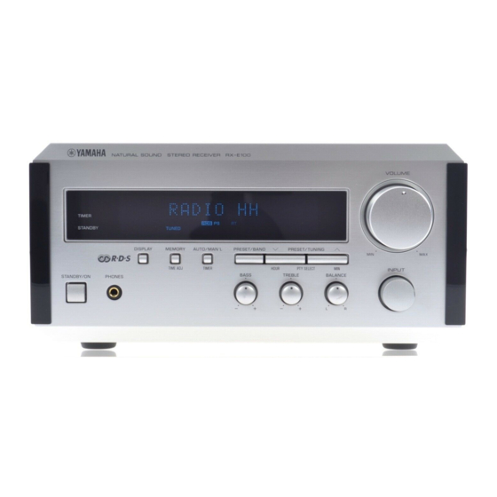
Page 3: Rear Panels
RX-E100 REAR PANELS U model B model C model G model R model A model... -
Page 4: Specifications
RX-E100 SPECIFICATIONS AUDIO SECTION FM SECTION Minimum RMS Output Power per Channel Tuning Range 20Hz to 20kHz, 0.1% THD, 6Ω U, C models ..... . . 87.5 to 107.9MHz U, C, A, B, G models . -
Page 5: Internal View
RX-E100 DIMENSIONS 217(8-9/16") Units : mm (inch) INTERNAL VIEW P. C. B. MAIN (6) P. C. B. MAIN (1) P. C. B. TUNER P. C. B. MAIN (2) P. C. B. OPERATION POWER TRANSFORMER P. C. B. MAIN (4) P. C. B. MAIN (3) -
Page 6: Disassembly Procedures
RX-E100 DISASSEMBLY PROCEDURES (Remove parts in disassembly order as numbered.) 2. Checking the Amp Unit and replacing parts 1. Removal of Top Cover a. Remove 4 screws ( q ) and 4 screws ( w ) in Fig. a. Disconnect the power plug from AC outlet. b. -
Page 7: Test Mode
RX-E100 TEST MODE POWER Off condition STANDBY/ON Key is pushed while pushing DISPLAY Key and AUTO/MAN'L Key. TEST MODE indication. When present mode is TEST MODE DOWN TEST MODE UP carried out. PRESET/TUNING B Key PRESET/TUNING N Key PRESET/BAND Key Test mode number Test mode number Executive test mode. -
Page 8: Amp Adjustments
RX-E100 FACTORY PRESET PRESET No. BAND MARKETS U, C, R (100k/10k) 98.1 95.1 87.5 101.5 107.9 88.1 106.1 107.9 FM (MHz) A, B, G, R, (50k/9k) 98.10 95.10 87.50 101.50 108.00 88.10 106.10 107.90 U, C, R (100k/10k) 1080 1400 1710 1350 1440... -
Page 9: Tuner Adjustments
RX-E100 TUNER ADJUSTMENTS Measuring Instruments Dummy antenna FM signal generator (FM SG) FM dummy antenna Stereo signal generator (SSG) 10Ω 45Ω AM signal generator (AM SG) RECEIVER FM SG (75Ω) Distortion meter (DIST. M) (50Ω) AC voltmeter (ACVM) DC voltmeter (DCVM) E2 (dB) = E1 (dB) —6 (dB) Oscilloscope Low pass filter (YLF-15, fc=15kHz) - Page 10 RX-E100 * : Execution of FACTORY PRESET (Refer to page 7.) will facilitate setting reception frequency for adjustment. Reception Adjusted Signal (ANT IN) Test point Step Adjustment item Rating frequency point FM ANT (75Ω) 98.1MHz Both ends of R24 Adjustment of DC 0V±50mV 98.1MHz ±...
- Page 11 RX-E100 AM Adjustment (This should be done after FM adjustment.) Connection Diagram (Measuring instruments) 1) Sensitivity verification AM loop antenna AM ANT ACVM TUNER AM SG dummy P. C. B. antenna DIST. M Oscilloscope Reception Adjustment Adjustment item Test point Signal (ANT IN) Rating Step...
-
Page 12: Ic Data
RX-E100 IC DATA IC501 : M30217M8-A100FP (16 bit µ-COM) P67/FLD7 P24/FLD36 P66/FLD6 P25/FLD37 P65/FLD5 P26/FLD38 P64/FLD4 P27/FLD39 P63/FLD3 P30/FLD40 P62/FLD2 P31/FLD41 P61/FLD1 P32/FLD42 P60/FLD0 P33/FLD43 P34/FLD44 P107/AN7 P35/FLD45 P106/AN6 P36/FLD46 P105/AN5 P37/FLD47 P104/AN4 P40/FLD48 P103/AN3 P41/FLD49 P102/AN2 P42/FLD50 P101/AN1 P43/FLD51 AVSS P44/TXD0/FLD52 P100/AN0... - Page 13 RX-E100 IC501 : M30217M8-A100FP (16 bit µ-COM) PORT Name IN/OUT Function C2B(LC72131/LC72720/LC78211)CE OUT [1:DATA transmission] S-CLK LC72131/LC72720/LC78211 CLK OUT (Serial I/O-1) DAT I S-IN LC72131/LC72720 DATA IN (Serial I/O-1) DAT O S-OUT LC72131/LC72720/LC78211 DATA OUT (Serial I/O-1) Mut A AMP MUTE OUT [0:MUTE ON] Mut T Tuner MUTE OUT (TUNER)
- Page 14 RX-E100 IC501 : M30217M8-A100FP (16 bit µ-COM) PORT Name IN/OUT Function SEG 25 SEGMENT 25 (P25) (VEE internal pull-down) SEG 26 SEGMENT 26 (P26) (VEE internal pull-down) SEG 27 SEGMENT 27 (P27) (VEE internal pull-down) SEG 28 SEGMENT 28 (P28) (VEE internal pull-down) SEG 29 SEGMENT 29 (P29)
-
Page 15: Block Diagram
RX-E100 BLOCK DIAGRAM TU-03 (TUNER AM/FM) 10.7MHz —VP CERAMIC CERAMIC FILTER FILTER IF AMP L.P.F TUNER.R 2 81 82 FM IN TUNER REST FLUORESCENT DISPLAY V501 IC502 CB502 INPUT REMOTE Q506 Q501 Q503 L.P.F Q505 AM/FM IF EEPROM SELECTER SENSOR Q504 FM OSC TUNER.L... - Page 16 RX-E100 PRINTED CIRCUIT BOARD (Foil side) Semiconductor Location P.C.B. TUNER P.C.B. TUNER Ref. No. Location Ref. No. Location Ref. No. Location (Lead Type Device View) (Surface Mount Device View) TUMUTE TUCE TUDATA TUCLK TUDO STAD STEIN CIRCUIT CHANGES BY MARKET. U, C, R, T L, A B, G...
- Page 17 RX-E100 PRINTED CIRCUIT BOARD (Foil side) P. C. B. OPERATION (Lead Type Device View) #503 W503 TO : MAIN (4) FROM : MAIN (1) AUDIO PRO-PS FAN-FE VOL-DN FAN-DR SYS-I/O VOL-UP PRO-I RLY-SP TIMER DAT-O DAT-I MUT-T MUT-A STANDBY STMO AUTO/ PRESET/TUNING PRESET/BAND...
- Page 18 RX-E100 PRINTED CIRCUIT BOARD (Foil side) Semiconductor Location Ref. No. Location Ref. No. Location Ref. No. Location D107 IC101 Q103 D108 IC103 Q104 D109 Q105 P. C. B. MAIN ( 1 ) Q106 D110 Q107 D111 Q108 D112 Q109 D115 Q110 D116 Q111...
- Page 19 RX-E100 PRINTED CIRCUIT BOARD (Foil side) P. C. B. MAIN ( 2 ) P. C. B. MAIN ( 3 ) P. C. B. MAIN ( 4 ) FROM : POWER TRANSFORMER ST/MO MUT-T V-DN DAT-I V-UP —15V DAT-O MUT-T DAT-I DAT-D ST-MO W103...
-
Page 20: Pin Connection Diagram
RX-E100 PRINTED CIRCUIT BOARD (Foil side) PIN CONNECTION DIAGRAM R model Diodes P. C. B. MAIN ( 7 ) P. C. B. MAIN ( 5 ) µPC4570HA NJM2068L-D LB1641 1SS133 1SS270A 1SR139-400 HZS5A2TD HZS5C2TD W113 Anode HZS12A2TD TO : MAIN (6) HZS152TD W112 HZS302TD... -
Page 21: Schematic Diagram
RX-E100 Each voltage represents the voltage when receiving FM (stereo) signal and the voltage in the parentheses ( ) is the voltage when receiving AM signal. SCHEMATIC DIAGRAM (TUNER) PK1 : TFFJ2U515A (V4299000) U, C, R, T, L models 0.01µ IF OUT OPEN VT (U, C, R, T, L, A, B, G) - Page 22 RX-E100 SCHEMATIC DIAGRAM (OPERATION) P-E28/J26 [I-2] V501 : 16-BT-67GN (V3579300) PATTERN AREA PIN CONNECTION -24.1 -29.1 NOTE 1) F1, F2 ..Filament 4) P1~P35 ..Datum Line 2) NP ..... No pin 5) 1G~16G ..Grid 3) NX ..... No extend pin 6) IC ....
- Page 23 RX-E100 SCHEMATIC DIAGRAM (MAIN) IC103 : LB1641 Motor Driver P-E27/J25 SUB POWER SUPPLY [H-4] 11.9 AC12.0 11.9 AC4.4 P-E27/J25 [F-1] IN 1 INPUT LOGIC IN 2 MAIN POWER SUPPLY AC58.4 CIRCUIT CHANGES BY MARKET P-E26/J24 P-E27/J25 35.6 14.2 [I-5] [C-8] 37.6 14.7 -37.7...
-
Page 24: Remote Control Transmitter
RX-E100 REMOTE CONTROL TRANSMITTER SCHEMATIC DIAGRAM 2N3904 2N3904 OPTION VBAT 1.5V x 4 OPTION KI/O0 KI/O1 100µF KI/O2 0.1µF KI/O3 KI/O4 VBAT VBAT KI/O5 10Ω 10Ω KI/O6 KI/O7 1kΩ OPTION SS8050D Q7~Q10:2N3904 100µF OSC0 455kHz 100µF OSC1 U, C, R, A models B, G models U, C, R, A models B, G models... -
Page 25: Parts List
RX-E100 P ARTS LIST WARNING Components having special characteristics are marked and must be replaced with parts having specifications equal to those originally installed. ELECTRICAL PARTS Carbon resistors (1/6W or 1/4W) are not included in the ELECTRICAL PARTS List. For the part Nos. of the carbon resistors, refer to the last page. ABBREVIATIONS IN THIS LIST ARE AS FOLLOWS : C.A.EL.CHP : CHIP ALUMI. - Page 26 RX-E100 P.C.B. MAIN Schm Schm Ref. PART NO. Description Ref. PART NO. Description V4217700 P.C.B. MAIN(UC) C128 UR837100 C.EL 10uF V4217800 P.C.B. MAIN(R) * C129 VE326000 C.MYLAR.ML 0.1uF V4217900 P.C.B. MAIN(A) C130 UR837470 C.EL 47uF V4218000 P.C.B. MAIN(B) * C131 VE326000 C.MYLAR.ML 0.1uF V4218100 P.C.B.
- Page 27 RX-E100 P.C.B. MAIN Schm Schm Ref. PART NO. Description Ref. PART NO. Description C186 UA954220 C.MYLAR 0.022uF HS102 VR506800 HEAT.SINK PUH16-25(R) C187 UR838100 C.EL 100uF IC100 XP894A00 IC LC78211 C188 UR866470 C.EL 4.7uF IC101 XM356A00 IC NJM2068LD C189 UR838100 C.EL 100uF IC103 XF494A00 IC LB1641...
- Page 28 RX-E100 P.C.B. MAIN & OPERATION Schm Schm Ref. PART NO. Description Ref. PART NO. Description R190 VV901100 R.MTL.OXD 120Ω VQ368600 PUSH.RIVET P3555-B R193 HV756270 R.CAR.FP 2.7KΩ 1/4W EP600830 SCR.BND.HD 3x8 FCRM3-BL R194 HV753470 R.CAR.FP 4.7Ω 1/4W EP600140 SCR.BND.HD 3x10 MFZN2-BL R195 VK188400 R.FUS 330Ω...
- Page 29 RX-E100 P.C.B. OPERATION & TUNER Schm Schm Ref. PART NO. Description Ref. PART NO. Description * Q505 VR412800 TR 2SC4481 T,U V5000200 P.C.B. TU-03(UCR) Q506 VV556500 TR 2SA1037K Q,R,S V5000300 P.C.B. TU-03(A) * R549 RD556180 R.THCK.CHP 1.8KΩ 1/10W V5000400 P.C.B. TU-03(BG) * R550 RD556180 R.THCK.CHP 1.8KΩ...
- Page 30 RX-E100 P.C.B. TUNER Schm Schm Ref. PART NO. Description Ref. PART NO. Description UR837100 C.EL 10uF RD254330 R.CAR.CHP 33Ω 1/10W VJ899500 C.CE.M.CHP 10pF RD254510 R.CAR.CHP 51Ω 1/10W VJ899500 C.CE.M.CHP 10pF RD255100 R.CAR.CHP 100Ω 1/10W UB052100 C.CE.M.CHP 100pF RD255220 R.CAR.CHP 220Ω 1/10W UR817470 C.EL 47uF...
-
Page 31: Exploded View
RX-E100 EXPLODED VIEW R model 2-20 2-22 2-22 2-14 B, G models 2-12 2-11 2-21 2-23 2-20 2-15 2-23 J, R, A, B, G models 2-22 2-24 U, C models U, C models 2-13 R model J, U, C, A, B, G 2-1 (8) models 1-21... - Page 32 RX-E100 MECHANICAL PARTS Ref. PART NO. Description Remarks Markets ! 1- 1 V4193900 P.C.B. ASS’Y SI:OPERATION * 1-10 MF120160 FLEXIBLE FLAT CABLE 20P 160mm * 1-11 V3685500 FRONT PANEL (UCRA) * 1-11 V3685600 FRONT PANEL (BG) * 1-11 V3809500 FRONT PANEL (UCRA) * 1-11 V3809600 FRONT PANEL...
- Page 33 RX-E100 Ref. PART NO. Description Remarks Markets * 103 V3682400 REAR PANEL * 103 V3682500 REAR PANEL * 104 V3684900 FRAME, FAN * 105 VZ679700 DAMPER T8/PCB * 110 V3688500 LEG M0080-M0 * 111 V3686300 KNOB * 111 V3686400 KNOB * 112 V3687600 KNOB * 112...
-
Page 34: System Control
RX-E100 SYSTEM CONTROL Features • One bus line controls all the units. • Units are connected in series, using monaural mini jacks. • Units can be connected in any order Description of Operation Bus line RX CPU CDX CPU M DX CPU K X CPU Serial Data Format 12mS... - Page 35 RX-E100 Description of data transmission and reception Microprocessor peripheral circuit q Although there is only 1 bus line, prepare special ports for data transmission and reception at each CPU. Transmission w The bus data consists of a header and data (8 bits). CPU receives and transmits at a 0.5mS or less timer System cable interruption.
- Page 36 RX-E100 2) FUNCTION [(5) to (6)] • No source other than that selected by the input selector will be reproduced. • The functions are selected automatically to be suitable for the source to be reproduced. • Selecting the functions is prohibited during recording. 3) TIMER operation [(7) to (8)] •...
- Page 37 RX-E100 ( 1 ) POWER ON PROCESSING ( Receiver ) When the power is turned on at the receiver, the relay of the AC outlet is turned on to supply power to each unit. Each unit informs the receiver of its status when started (secondary connection status). Remarks The indicator of each POWER SW ON...
- Page 38 RX-E100 (4)POWER OFF processing (except receiver) When the power is turned off at a unit other than the receiver, the unit informs the receiver of the status when the power off processing has been completed. Remarks POWER OFF The receiver detects the units being After POWER OFF processing connected when...
- Page 39 RX-E100 (7)TIMER PLAY Timer play by built-in timer Remarks Timer time reached This function is Execution of ignored when no PLAY unit is (1) Power ON processing connected. (Receiver) Function selection [FUNC_CD] [FUNC_MD] [FUNC_TAPE] [FUNC_TU] [FUNC_AUX] Timer play command transmitted when PLAY unit is CD, MD or TAPE [CD_TPLAY]...
- Page 40 RX-E100 (9)AUTO POWER OFF The receiver turns off the power when the unit is left at stop for half an hour without any operation. Remarks When the unit is left at stop without any key operation Auto power off request [APOFF_REQ] When a CD request is made for the first...
- Page 41 RX-E100 (10)AUTO POWER ON Function to turn ON the power without using the power switch on the unit other than the receiver Remarks Auto power ON applicable key Auto power ON applicable key Auto power ON applicable key input input input When in the power OFF state When in the power OFF state...
- Page 42 RX-E100 Function CODE CODE CODE CODE CD_STOP Remote control CD_PLAY/PAUSE CD_EJECT CD_SKIP+ CD_SKIP- SEARCH+ SEARCH- SEACH_END CD_RANDAM CD_TIME CD_PRG CD_RPT TAPE PEAK SEARCH CD_0 CD_1 CD_2 CD_3 CD_4 CD_5 CD_6 CD_7 CD_8 CD_9 CD_10 MD_STOP MD_PLAY/PAUSE MD_EJECT MD_SKIP+ MD_SKIP- SEARCH+ SEARCH- SEACH_END MD_RANDAM...
- Page 43 RX-E100 Reception status of operation switches during recording (*=AUX or TUNER) EDIT or EDIT(TR-1) RECORDING SYNCHRONOUS or MANUAL RECORDING Unit C^T,M *^T,M POWER FUNCTION POWER EJECT PLAY STOP SKIP SEARCH POWER EJECT PLAY STOP SKIP SEARCH TAPE POWER EJECT PLAY STOP FF/REW Principle of switch rec operation reception...
-
Page 44: Nx-E100
RX-E100 NX-E100 TWEETER (XW275A00) 2.7Ω/5W 3.3µF/100V WOOFER INPUT (XW276A00) 1.0mH Ref. PART NO. Description Remarks Markets AAX07740 CABINET ASS’Y AA13000901 XW275A00 SPEAKER 2.5cm XR02502701 XW276A00 SPEAKER 13cm CR13005301 AAX07790 FRONT GRILLE ASS’Y AA13001001 V2192200 EMBLEM 5900015501 AAX07800 HOLDER 5600003101 EM030180 FLAT HEAD TAPPING SCREW 3.5x20 MFZN2-BL 7002792002 AAX07770 TAPPING SCREW... -
Page 45: Parts List For Carbon Resistors
RX-E100 Parts List for Carbon Resistors Value 1/4W Type Part No. 1/6W Type Part No. Value 1/4W Type Part No. 1/6W Type Part No. 1.0 Ω 3100 3100 7100 10 kΩ 7100 HJ35 HF85 HF45 HF45 1.8 Ω 3180 7110 11 kΩ...
Need help?
Do you have a question about the CRX-E100 and is the answer not in the manual?
Questions and answers