Table of Contents
Advertisement
QQ
3 7 63 1515 0
CRX-E150/
TE
L 13942296513
CONTENTS
TO SERVICE PERSONNEL ...................................... 1~2
FRONT PANELS ............................................................ 3
REAR PANELS .............................................................. 4
SPECIFICATIONS ...................................................... 5~6
INTERNAL VIEW ........................................................... 6
DISASSEMBLY PROCEDURES ............................... 7~8
CD MECHANISM UNIT OPERATION CHECK ............. 9
TEST MODE ........................................................... 10~11
CD TEST MODE ........................................................... 12
www
CD STANDARD OPERATION CHART ................. 13~14
.
1 0 0 7 4 4
http://www.xiaoyu163.com
MINI COMPONENT SYSTEM
This manual has been provided for the use of authorized YAMAHA Retailers and their service personnel.
It has been assumed that basic service procedures inherent to the industry, and more specifically YAMAHA Products, are already
known and understood by the users, and have therefore not been restated.
WARNING:
Failure to follow appropriate service and safety procedures when servicing this product may result in personal
injury, destruction of expensive components, and failure of the product to perform as specified. For these reasons,
we advise all YAMAHA product owners that any service required should be performed by an authorized
YAMAHA Retailer or the appointed service representative.
IMPORTANT:
The presentation or sale of this manual to any individual or firm does not constitute authorization, certification or
recognition of any applicable technical capabilities, or establish a principle-agent relationship of any form.
The data provided is believed to be accurate and applicable to the unit(s) indicated on the cover. The research, engineering, and
service departments of YAMAHA are continually striving to improve YAMAHA products. Modifications are, therefore, inevitable
and specifications are subject to change without notice or obligation to retrofit. Should any discrepancy appear to exist, please
contact the distributor's Service Division.
WARNING:
Static discharges can destroy expensive components. Discharge any static electricity your body may have
accumulated by grounding yourself to the ground buss in the unit (heavy gauge black wires connect to this buss).
IMPORTANT:
Turn the unit OFF during disassembly and part replacement. Recheck all work before you apply power to the unit.
x
ao
u163
y
i
http://www.xiaoyu163.com
2 9
8
SERVICE MANUAL
IMPORTANT NOTICE
Q Q
3
6 7
1 3
1 5
CD ERROR MESSAGE ......................................... 15~16
AMP ADJUSTMENTS .................................................. 17
IC DATA ................................................................. 18~26
DISPLAY DATA ........................................................... 27
BLOCK DIAGRAM ................................................. 28~31
PRINTED CIRCUIT BOARD .................................. 32~41
SCHEMATIC DIAGRAM ........................................ 42~45
REMOTE CONTROL TRANSMITTER ........................ 46
PARTS LIST ........................................................... 47~59
SYSTEM CONTROL .............................................. 60~68
NX-E150 ....................................................................... 69
co
.
9 4
2 8
NX-E150
0 5
8
2 9
9 4
2 8
m
P.O.Box 1, Hamamatsu, Japan
9 9
9 9
Advertisement
Table of Contents

Related Manuals for Yamaha CRX-E150


Summary of Contents for Yamaha CRX-E150
-
Page 1: Table Of Contents
This manual has been provided for the use of authorized YAMAHA Retailers and their service personnel. It has been assumed that basic service procedures inherent to the industry, and more specifically YAMAHA Products, are already known and understood by the users, and have therefore not been restated. -
Page 2: To Service Personnel
CRX-E150 3 7 63 1515 0 AC LEAKAGE TO SERVICE PERSONNEL WALL EQUIPMENT TESTER OR OUTLET UNDER TEST EQUIVALENT 1. Critical Components Information Components having special characteristics are marked s a n d m u s t b e r e p l a c e d w i t h p a r t s h a v i n g specifications equal to those originally installed. -
Page 3: Prevention Of Electro Static Discharge
CRX-E150 3 7 63 1515 0 PROTECTION OF EYES FROM LASER BEAM DURING SERVICING This set employs a laser. Therefore, be sure to carefully follow the instructions below when servicing. Optical Pick-up 1. Laser Diode Properties • Material : GaAlAs •... -
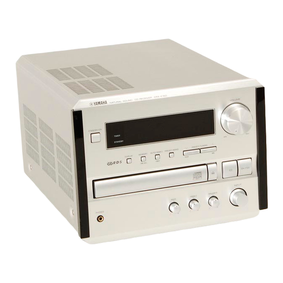
Page 4: Front Panels
Conductive material through the wrist strap. So take care not to let your clothes (sheet) or steel sheet touch the optical pickup. FRONT PANELS U, C, A, R, T models NATURAL SOUND CD RECEIVER CRX-E150 VOLUME STANDBY/ON TIMER STANDBY DISPLAY... -
Page 5: Rear Panels
CRX-E150 3 7 63 1515 0 REAR PANELS U, C models A model B model G model L 13942296513 R, T models u163 http://www.xiaoyu163.com... -
Page 6: Specifications
CRX-E150 3 7 63 1515 0 SPECIFICATIONS Audio Section FM Section Minimum RMS Output Power per Channel (Power Amp. Section) Tuning Range (1 kHz, 0.1% THD, 6 ohms) [U, C models] ........... 87.5 to 107.9 MHz SP OUT L/R ..............25W + 25W [A, B, G models] ........... -
Page 7: Internal View
CRX-E150 3 7 63 1515 0 • DIMENSIONS SPEAKER Section (NX-E150) Type ......... 2 Way Bass-reflex Magnetic Shielding Type Driver Woofer ........... 11cm (4-1/2") Cone Type Tweeter ............. 2.5cm (1") Dome Type Frequency Response ................60 Hz to 28 kHz Impedance .................... -
Page 8: Disassembly Procedures
CRX-E150 3 7 63 1515 0 DISASSEMBLY PROCEDURES Top Cover (Remove parts in the order as numbered.) Disconnect the power plug from the AC outlet. 1. Removal of Top Cover a. Remove 4 screws (1) and 5 screws (2) in Fig. 1. - Page 9 CRX-E150 3 7 63 1515 0 6. Removal of Tray Unit Stopper Pin Chucking Unit a. Remove 2 screws (E) and then remove the Chucking Unit in Fig. 5. b. Remove 1 hook and then remove the Stopper Pin in Stopper Fig.
-
Page 10: Cd Mechanism Unit Operation Check
CRX-E150 3 7 63 1515 0 CD MECHANISM UNIT OPERATION CHECK Refer to the DISASSEMBLY PROCEDURES and the EXPLODED VIEW. CB403 CB601 1. Disconnect the power plug from the AC outlet. 2. Remove the top cover. 3. Remove the front panel unit. -
Page 11: Test Mode
CRX-E150 3 7 63 1515 0 TEST MODE POWER Off condition STANDBY/ON Key is pressed while pressing DISPLAY Key and AUTO/MAN'L Key. TEST MODE indication. When present mode is TEST MODE DOWN TEST MODE UP carried out. PRESET/TUNING PRESET/TUNING... - Page 12 CRX-E150 3 7 63 1515 0 (*1) DESTINATION R (AM9k/FM:50k) R (AM10k/FM100k) Display R10k B, G U, C (*2) Contents of indication change by the microcomputer software. CAUTION : When executing Test mode No. 2 RAM CLEAR, be sure to write down the preset memory contents of the tuner, using a table like the one shown below.
-
Page 13: Cd Test Mode
CRX-E150 3 7 63 1515 0 CD TEST MODE Press the ”STANDBY/ON” key while pressing the ”STOP” key and the ”PLAY/PAUSE” key simultaneously, and TEST MODE will be activated. On the FL display, an opening message appears for a few seconds. -
Page 14: Cd Standard Operation Chart
CRX-E150 3 7 63 1515 0 CD STANDARD OPERATION CHART POWER ON If a disc is not loaded, “No Disc” appears on the FL display. Press OPEN/CLOSE key. “01 OPEN” appears on the FL display. “TRV” signal is output until detection of LIMIT switch. - Page 15 CRX-E150 3 7 63 1515 0 Tracking gain rough ADJ Tracking balance ADJ (only tray OPEN/CLOSE) Focus balance ADJ Focus gain ADJ Tracking gain ADJ * TOC READ ~ * Data fetch cycle ~ TRACK NO. “1” is searched.
-
Page 16: Cd Error Message
CRX-E150 3 7 63 1515 0 CD ERROR MESSAGE (1) If a CD error occurs, an error message can be displayed by holding down the “MEMORY” key and pressing the “PRESET/BAND” key. (2) Shown below is an example of display. (“E-73” as an example) (3) Listed in the table below are error messages. - Page 17 CRX-E150 3 7 63 1515 0 c) Operates as if no disc loaded. (although loaded) 2) Troubleshooting from System Malfunctions a) Tray fails to come out/go in. Does tray Poor tray loading load properly? Poor mechanism Tray starts to operation move but stops.
-
Page 18: Amp Adjustments
CRX-E150 3 7 63 1515 0 AMP ADJUSTMENTS Confirmation of Idling Current 1) No signal applied. 2) Non-loaded condition. 3) Aging is not neccessary. Item Test Point Rating (DC) Note R460 If the measured voltage exceeds 5mV, cut the lead wire of R446 (L... -
Page 19: Ic Data
CRX-E150 3 7 63 1515 0 IC DATA IC102 : MN35511AL Signal Processor & Controller 58 59 56 19 49 8 7 9 44 46 45 47 48 52 53 67 62 15 14 68 73 72 74 75 13 55... - Page 20 CRX-E150 3 7 63 1515 0 IC102 : MN35511AL Pin Description Pin No. Name Function BCLK Bit clock output for SR DATA (NC) LRCK L/R identification signal output (NC) SRDATA Serial data output (NC) DVDD1 Power supply for digital circuit...
- Page 21 CRX-E150 3 7 63 1515 0 Pin No. Name Function DSLF Loop filter terminal for DSL PLLF Loop filter terminal for PLL VCOF Loop filter terminal for VCO (+5) AVDD2 Power supply for analog circuit (for AD of DSL, PLL, DA output blocks)
-
Page 22: Top View
CRX-E150 3 7 63 1515 0 IC103 : M38B59MFH 8 bit µ-COM TOP VIEW L 13942296513 P00 – P08 P11 – P17 P20 – P27 P30 – P37 P40 – P47 56 – 49 48 – 44 64 – 57 40 –... - Page 23 CRX-E150 3 7 63 1515 0 IC103 : M38B59MFH Pin Description Port Name Function /OPSW Opened state of tray sensing switch input. Opened state at "L" /CLSW Closed state of tray sensing switch input. Opened state at "L" TROP...
- Page 24 CRX-E150 3 7 63 1515 0 Port Name Function MUTE Line Mute [NC] [NC] [NC] [NC] [NC] [NC] [NC] [NC] SQCK Serial clock to servo LSI (Qcode) MCLK Serial clock to servo LSI (Command) SOUT Serial out to servo LSI (Command)
- Page 25 CRX-E150 3 7 63 1515 0 IC202 : M30217M8-XXXXFP 16 bit µ-COM P67/FLD7 P24/FLD36 P66/FLD6 P25/FLD37 P65/FLD5 P26/FLD38 P64/FLD4 P27/FLD39 P63/FLD3 P30/FLD40 P62/FLD2 P31/FLD41 P61/FLD1 P32/FLD42 P60/FLD0 P33/FLD43 P34/FLD44 P107/AN7 P35/FLD45 P106/AN6 P36/FLD46 P105/AN5 P37/FLD47 P104/AN4 P40/FLD48 P103/AN3 P41/FLD49...
- Page 26 CRX-E150 3 7 63 1515 0 PORT Name IN/OUT Function C2B(LC72131/LC72720/LC78211)CE OUT [1:DATA transmission] S-CLK LC72131/LC72720/LC78211 CLK OUT (Serial I/O-1) DAT I S-IN LC72131/LC72720 DATA IN (Serial I/O-1) DAT O S-OUT LC72131/LC72720/LC78211 DATA OUT (Serial I/O-1) ST/MO STEREO/MONO IN (TUNER)
-
Page 27: Display Data
CRX-E150 3 7 6 3 1 5 1 5 0 PORT Name IN/OUT Function DISPLAY DATA SEG 25 SEGMENT 25 (P25) (VEE internal pull-down) SEG 26 SEGMENT 26 (P26) (VEE internal pull-down) V301 : 16-BT-84GN (V6253100) SEG 27 SEGMENT 27 (P27) -
Page 28: Block Diagram
CRX-E150 3 7 6 3 1 5 1 5 0 BLOCK DIAGRAM (1/2) OPERATION See page E-43/J-39 BACKUP CAPACITOR FOR TIMER ONLY C210 MAIN See page E-45/J-41 See page 1 3 9 4 2 2 9 6 5 1 3... - Page 29 CRX-E150 3 7 6 3 1 5 1 5 0 BLOCK DIAGRAM (2/2) See page E-44/J-40 1 3 9 4 2 2 9 6 5 1 3 w w w u 1 6 3 E-30/J-26 E-31/J-27 http://www.xiaoyu163.com...
-
Page 30: Printed Circuit Board
CRX-E150 3 7 6 3 1 5 1 5 0 Circuit No. J, U, C, A B, G R, T PRINTED CIRCUIT BOARD (Foil side) C341~346, 348, 350~351 IC306 L301, 302 Q304 From MAIN (1) R356~358, 360 INPUT (1) P. C. B. - Page 31 CRX-E150 3 7 6 3 1 5 1 5 0 PRINTED CIRCUIT BOARD (Foil side) To INPUT (1) From MAIN (1) OPERATION P. C. B. (Lead Type Device) From INPUT (2) STANDBY/ 22 21 1 3 9 4 2 2 9 6 5 1 3...
- Page 32 CRX-E150 3 7 6 3 1 5 1 5 0 PRINTED CIRCUIT BOARD (Foil side) CD P. C. B. To MAIN (1) To CD Mechanism (Lead Type Device) (Surface Mount Device) Unit DGND MGND MGND AGND 20 21 1 3 9 4 2 2 9 6 5 1 3 64 65 •...
- Page 33 CRX-E150 3 7 6 3 1 5 1 5 0 • Semiconductor Location Circuit No. U, C A, B R, T PRINTED CIRCUIT BOARD (Foil side) C434 C464, 466, 469, 470 Ref. No. Location CB408, 409 D401 D411 F401...
- Page 34 CRX-E150 3 7 6 3 1 5 1 5 0 Circuit No. J, U, C, A, B, G R, T PRINTED CIRCUIT BOARD (Foil side) CB404, 405 F402 SW401 W401~406 From MAIN (1) X: NOT USED MAIN (2) P. C. B.
-
Page 35: Schematic Diagram
CRX-E150 SCHEMATIC DIAGRAM (INPUT) IC301~303, 751: NJM2068D-D IC304: LC78211 IC305: NJM78L05A-T3 IC306: LC72722 IC752: LB1641 3 7 6 3 1 5 1 5 0 Dual OP-Amp. Analog Function Switch Voltage Regulator RDS Decoder Motor Driver INPUT VDDA CLOCK VDDD... - Page 36 CRX-E150 SCHEMATIC DIAGRAM (OPERATION) 3 7 6 3 1 5 1 5 0 FLUORESCENT DISPLAY -25.3 -30.3 Point 1 Pin 13 of IC202 Point 2 Pin 11 of IC202 µ-COM -30.1 -30.3 M30217M8 EEPROM 0 4.8 1 3 9 4 2 2 9 6 5 1 3...
- Page 37 CRX-E150 SCHEMATIC DIAGRAM (CD) IC1: AN8785SB 3 7 6 3 1 5 1 5 0 5-Channel Power OP-Amp System Driver CD HEAD AMP Thermal Protection Circuit Standby Band gap Reset Circuit FROM 1.25V MECHANISM UNIT VREF DSP-DAC LD DRIVE...
- Page 38 CRX-E150 SCHEMATIC DIAGRAM (MAIN) 3 7 6 3 1 5 1 5 0 SUB POWER SUPPLY 11.5 11.5 11.6 14.9 29.4 VOLTAGE SELECTOR TO MAIN (2) FROM MAIN (1) E-45/J-41 11.5 240V 1-2/5-6 E-45/J-41 TO MAIN (2) E-45/J-41 220V...
-
Page 39: Remote Control Transmitter
CRX-E150 3 7 63 1515 0 REMOTE CONTROL TRANSMITTER I SCHEMATIC DIAGRAM KI/O6 KI/O5 KI/O7 KI/O4 KI/O3 KI/O2 KI/O1 2SD1781KR 220Ω DC3V B1 KI/O0 X OUT X IN 455kHz 47µF/16 RESET 0.1µF L 13942296513 TRANSMISSION FORMAT: NEC-FORMAT CUSTOM CODE (HEX): 78... -
Page 40: Parts List
CRX-E150 I WARNING PARTS LIST Components having special characteristics are marked s and must be replaced with parts having specifications equal to those originally in- 3 7 63 1515 0 stalled. I ELECTRICAL PARTS Carbon resistors (1/6W or 1/4W) are not included in the ELECTRICAL PARTS List. - Page 41 CRX-E150 3 7 63 1515 0 P.C.B. INPUT Schm Schm Ref. PART NO. Description Markets Ref. PART NO. Description Markets L 13942296513 u163 ✻ New Parts ✻ New Parts http://www.xiaoyu163.com...
- Page 42 CRX-E150 3 7 63 1515 0 P.C.B. INPUT, P.C.B. OPERATION & P.C.B. CD Schm Schm Ref. PART NO. Description Markets Ref. PART NO. Description Markets L 13942296513 u163 ✻ New Parts ✻ New Parts http://www.xiaoyu163.com...
- Page 43 CRX-E150 3 7 63 1515 0 P.C.B. CD & P.C.B. MAIN Schm Schm Ref. PART NO. Description Markets Ref. PART NO. Description Markets L 13942296513 u163 ✻ New Parts ✻ New Parts http://www.xiaoyu163.com...
- Page 44 CRX-E150 3 7 63 1515 0 P.C.B. MAIN Schm Schm Ref. PART NO. Description Markets Ref. PART NO. Description Markets L 13942296513 u163 ✻ New Parts ✻ New Parts http://www.xiaoyu163.com...
- Page 45 CRX-E150 3 7 63 1515 0 P.C.B. MAIN & Chip Resistors Schm Schm Ref. PART NO. Description Markets Ref. PART NO. Description Markets L 13942296513 u163 ✻ New Parts ✻ New Parts http://www.xiaoyu163.com...
- Page 46 CRX-E150 3 7 63 1515 0 I EXPLODED VIEW 1-10 1-11 1-110 1-111 1-104 1-111 1-103 1-12 1-101 1-110 1-102 1-103 13 (3) 2-101 R,T version 13 (6) 2-112 L 13942296513 2-105 13 (7) 2-111 u163 200-1 http://www.xiaoyu163.com...
- Page 47 CRX-E150 3 7 63 1515 0 I MECHANICAL PARTS Ref. PART NO. Description Remarks Markets L 13942296513 u163 ✻ New Parts http://www.xiaoyu163.com...
- Page 48 CRX-E150 3 7 63 1515 0 Ref. PART NO. Description Remarks Markets L 13942296513 ✻ New Parts ! : Note on the Operation P.C.B. u163 Of the Operation PCB part Nos., only the gold (GD) type part Nos. are included in the table.
- Page 49 CRX-E150 3 7 63 1515 0 I EXPLODED VIEW (CD Mechanism Unit) L 13942296513 Stopper u163 * The stopper is not supplied with the tray as a spare part. When replacing the tray, keep the removed stopper and reuse it.
- Page 50 CRX-E150 3 7 63 1515 0 I MECHANICAL PARTS (CD Mechanism Unit) Ref. PART NO. Description Remarks Markets L 13942296513 u163 ✻ New Parts http://www.xiaoyu163.com...
- Page 51 CRX-E150 3 7 63 1515 0 I EXPLODED VIEW (Drive Unit) Note: The parts marked with an asterisk ( ) are not available separately. Cover L 13942296513 Ref. PART NO. Description Remarks Markets u163 ✻ New Parts http://www.xiaoyu163.com...
-
Page 52: Parts List For Carbon Resistors
CRX-E150 3 7 63 1515 0 Parts List for Carbon Resistors Value 1/4W Type Part No. 1/6W Type Part No. Value 1/4W Type Part No. 1/6W Type Part No. 1.0 Ω 3100 3100 10 kΩ 7100 7100 HJ35 HF85... -
Page 53: System Control
CRX-E150 3 7 63 1515 0 SYSTEM CONTROL Features • One bus line controls all the units. • Units are connected in series, using monaural mini jacks. • Units can be connected in any order Description of Operation Bus line... - Page 54 CRX-E150 3 7 63 1515 0 Description of data transmission and reception Microprocessor peripheral circuit 1 Although there is only 1 bus line, prepare special ports for data transmission and reception at each CPU. Transmission 2 The bus data consists of a header and data (8 bits).
- Page 55 CRX-E150 3 7 63 1515 0 2) FUNCTION [(5) to (6)] • No source other than that selected by the input selector will be reproduced. • The functions are selected automatically to be suitable for the source to be reproduced.
- Page 56 CRX-E150 3 7 63 1515 0 (1) POWER ON PROCESSING (CRX) When the power is turned on at the CRX, the relay of the AC outlet is turned on to supply power to each unit. Each unit informs the CRX of its status when started (secondary connection status).
- Page 57 CRX-E150 3 7 63 1515 0 (4) POWER OFF processing (except CRX) When the power is turned off at a unit other than the CRX, the unit informs the CRX of the status when the power off processing has been completed.
- Page 58 CRX-E150 3 7 63 1515 0 (7) TIMER PLAY Timer play by built-in timer Remarks Timer time reached This function is Execution of ignored when no PLAY unit is (1) Power ON processing connected. (CRX) Function selection [FUNC_CD] [FUNC_MD]...
- Page 59 CRX-E150 3 7 63 1515 0 (9) AUTO POWER ON Function to turn ON the power without using the power switch on the unit other than the CRX Remarks Auto power ON applicable key Auto power ON applicable key...
- Page 60 CRX-E150 3 7 63 1515 0 Function CODE CODE CODE CD_STOP Remote control CD_PLAY/PAUSE CD_EJECT CD_SKIP+ CD_SKIP- SEARCH+ SEARCH- SEACH_END CD_RANDOM CD_TIME CD_PRG CD_RPT TAPE PEAK SEARCH CD_0 CD_1 CD_2 CD_3 CD_4 CD_5 CD_6 CD_7 CD_8 CD_9 CD_10 MD_STOP...
- Page 61 CRX-E150 3 7 63 1515 0 Reception status of operation switches during recording (*=AUX or TUNER) EDIT or EDIT(TR-1) RECORDING SYNCHRONOUS or MANUAL RECORDING Unit C→T C→M M→T T→M C→T C→M M→T T→M C→T,M *→M *→T *→T,M POWER FUNCTION...
-
Page 62: Nx-E150
CRX-E150 3 7 63 1515 0 NX-E150 L 13942296513 TWEETER (XW275A00) 2.7Ω/5W 3.3µF/63V WOOFER INPUT (XZ668A00) 1.0mH Ref. PART NO. Description Remarks Markets u163 ✻ New Parts http://www.xiaoyu163.com...
Need help?
Do you have a question about the CRX-E150 and is the answer not in the manual?
Questions and answers