Yamaha CRX-330 Service Manual
Cd receiver / speakers
Hide thumbs
Also See for CRX-330:
- Owner's manual (260 pages) ,
- Service manual (70 pages) ,
- Owner's manual (40 pages)
Table of Contents
Advertisement
MICRO COMPONENT SYSTEM
This service manual is for the CRX-330/NS-BP110/NS-BP100 (U, T, K, A, G, L, V and J models).
For service manual of the CRX-330/NS-BP110 (B model), please refer to the following publication number:
The MCR-330 consists of the CRX-330 and NS-BP110.
The MCR-230 consists of the CRX-330 and NS-BP100.
This manual has been provided for the use of authorized YAMAHA Retailers and their service personnel.
It has been assumed that basic service procedures inherent to the industry, and more specifi cally YAMAHA Products, are already known
and understood by the users, and have therefore not been restated.
WARNING:
IMPORTANT:
The data provided is believed to be accurate and applicable to the unit(s) indicated on the cover. The research, engineering, and service
departments of YAMAHA are continually striving to improve YAMAHA products. Modifications are, therefore, inevitable and
specifi cations are subject to change without notice or obligation to retrofi t. Should any discrepancy appear to exist, please contact the
distributor's Service Division.
WARNING:
IMPORTANT:
■ CONTENTS
To Service Personnel ........................................2–4
SYSTEM COMPOSITION / システム構成 .......................6
Front Panels .............................................................7
Rear Panels ......................................................... 8–10
Remote Control Panels ..................................... 11
SPECIFICATIONS / 参考仕様 ................................. 12–13
Internal View .......................................................... 14
DISASSEMBLY PROCEDURES / 分解手順 ........... 15–17
ファームウェアの書き込み ..................................... 18–23
1 0 1 1 2 6
CD RECEIVER /
NS-BP110/NS-BP100
SERVICE MANUAL
For U, T, K, A, G, L, V and J models
CRX-330/NS-BP110 (B model): 101137
MCR-330 は、CRX-330、NS-BP110 で構成されています。
MCR-230 は、CRX-330、NS-BP100 で構成されています。
IMPORTANT NOTICE
Failure to follow appropriate service and safety procedures when servicing this product may result in personal injury,
destruction of expensive components, and failure of the product to perform as specifi ed. For these reasons, we advise
all YAMAHA product owners that any service required should be performed by an authorized YAMAHA Retailer or
the appointed service representative.
The presentation or sale of this manual to any individual or fi rm does not constitute authorization, certifi cation or
recognition of any applicable technical capabilities, or establish a principle-agent relationship of any form.
Static discharges can destroy expensive components. Discharge any static electricity your body may have
accumulated by grounding yourself to the ground buss in the unit (heavy gauge black wires connect to this buss).
Turn the unit OFF during disassembly and part replacement. Recheck all work before you apply power to the unit.
SELF-DIAGNOSTIC FUNCTION /
ダイアグ(自己診断機能) .......................................24–38
Display Data .............................................................39
Ic Data ...................................................................40–46
Pin Connection Diagrams .............................47–48
Block Diagram ........................................................49
Printed Circuit Boards .................................50–55
Schematic Diagrams .......................................57–61
Replacement Parts List ................................63–79
Remote Control .....................................................80
Copyright © 2008
This manual is copyrighted by YAMAHA and may not be copied or
redistributed either in print or electronically without permission.
MCR-330/MCR-230
CRX-330/
All rights reserved.
SPEAKERS
P.O.Box 1, Hamamatsu, Japan
animate '08.12
Advertisement
Table of Contents

Related Manuals for Yamaha CRX-330


Summary of Contents for Yamaha CRX-330
-
Page 1: Micro Component System
This manual has been provided for the use of authorized YAMAHA Retailers and their service personnel. It has been assumed that basic service procedures inherent to the industry, and more specifi cally YAMAHA Products, are already known and understood by the users, and have therefore not been restated. - Page 2 CRX-330/NS-BP110/NS-BP100 ■ TO SERVICE PERSONNEL AC LEAKAGE 1. Critical Components Information WALL EQUIPMENT TESTER OR Components having special characteristics are marked OUTLET UNDER TEST EQUIVALENT must be replaced with parts having specifications equal to those originally installed. 2. Leakage Current Measurement (For 120V Models Only)
- Page 3 CRX-330/NS-BP110/NS-BP100 WARNING: Lithium batteries CAUTION 注意 Danger of explosion if battery is incorrectly replaced. 正しい電池と交換しないと爆発が起きるおそれがありま Replace only with the same or equivalent type. す。 同一型名または同等品以外の電池とは絶対に交換しない ようにしてください。 WARNING: ADVARSEL! Lithium batteries are dangerous because they can be exploded by improper handling. Observe the Lithiumbatteri –Eksplosionsfare ved fejlagtig håndtering.
- Page 4 CRX-330/NS-BP110/NS-BP100 Warning for power supply The primary side of the power supply carries live mains voltage when the player is connected to the mains even when the player is switched off ! This primary area is not shielded so it is possible to accidentally touch copper tracks and/or components when servicing the player.
- Page 5 CRX-330/NS-BP110/NS-BP100 ■ PREVENTION OF ELECTROSTATIC DISCHARGE Some semiconductor (solid state) devices can be damaged easily by static electricity. Such components commonly are called Electrostatically Sensitive (ES) Devices. Examples of typical ES devices are integrated circuits and some field-effect transistors and semiconductor “chip” components. The following techniques should be used to help reduce the incidence of component damage caused by electro static discharge (ESD).
-
Page 6: System Composition / システム構成
CRX-330/NS-BP110/NS-BP100 ■ SYSTEM COMPOSITION / システム構成 The MCR-330 consists of the CRX-330 and NS-BP110. MCR-330 は、CRX-330、NS-BP110 で構成されています。 The MCR-230 consists of the CRX-330 and NS-BP100. MCR-230 は、CRX-330、NS-BP100 で構成されています。 MCR-330 ▼ NS-BP110 ▼ NS-BP110 ▼ CRX-330 MCR-230 ▼ NS-BP100 ▼ NS-BP100... -
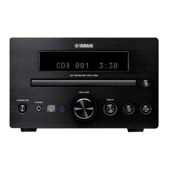
Page 7: Front Panels
CRX-330/NS-BP110/NS-BP100 ■ FRONT PANELS CRX-330 Top view Front view NS-BP110 NS-BP100... -
Page 8: Rear Panels
CRX-330/NS-BP110/NS-BP100 ■ REAR PANELS CRX-330 U model T model Bottom view K model A model... - Page 9 CRX-330/NS-BP110/NS-BP100 G model L model V model J model...
- Page 10 CRX-330/NS-BP110/NS-BP100 NS-BP110 U, K, A, G, L, V, J models T model NS-BP100 U, K, A, G, L, V, J models T model...
-
Page 11: Remote Control Panels
CRX-330/NS-BP110/NS-BP100 ■ REMOTE CONTROL PANELS U, T, K, A, G, L, V models J model... -
Page 12: Specifications / 参考仕様
CRX-330/NS-BP110/NS-BP100 ■ SPECIFICATIONS / 参考仕様 CRX-330 NS-BP110 NS-BP100 ■ Audio Section / オーディオ部 ■ Audio Section / オーディオ部 Minimum RMS Output Power (Power Amp. Section) / Type / 形式 ........2-way bass reflex speaker system Non-magnetic shielding type 定格出力(パワーアンプ部) (L/R drive, 1 kHz, 10 % THD, 6 ohms) ......20 W + 20 W 2 ウェイ・バスレフ... - Page 13 CRX-330/NS-BP110/NS-BP100 • DIMENSIONS / 寸法図 NS-BP110 CRX-330 NS-BP100 Top view Top view Top view 152 (5-15/16") Front view Front view Front view 180 (7-1/16") 123 (4-13/16") 123 (4-13/16") Unit: mm (inch) 単位 : mm(インチ) NS-BP110 Bottom view A screw with a diameter of 4 mm can be used.
-
Page 14: Internal View
CRX-330/NS-BP110/NS-BP100 ■ INTERNAL VIEW CRX-330 Top view POWER (1) P.C.B. FM TUNER MAIN (1) P.C.B. MAIN (2) P.C.B. POWER (2) P.C.B. LOADER MECHANISM UNIT Front view... -
Page 15: Disassembly Procedures / 分解手順
CRX-330/NS-BP110/NS-BP100 ■ DISASSEMBLY PROCEDURES / 分解手順 CRX-330 (Remove parts in the order as numbered.) (番号順に部品を取り外してください。 ) Disconnect the power cable from the AC outlet. AC 電源コンセントから、電源コードを抜いてください。 1. Removal of Top Cover Ass’y 1. トップカバー ASSY の外し方 ➀ ➁ ①のネジ 4 本、②のネジ 4 本を外します。 (Fig. 1)... - Page 16 CRX-330/NS-BP110/NS-BP100 3. Removal of Loader Mechanism Unit and 3. ローダーメカユニット、POWER (1) P.C.B. の外 POWER (1) P.C.B. し方 ➅ ⑥のネジ 5 本を外します。 (Fig. 2) Remove 5 screws ( ). (Fig. 2) b. Lift the POWER (1) P.C.B. and POWER support together.
- Page 17 CRX-330/NS-BP110/NS-BP100 When checking the P.C.B.s: P.C.B. をチェックする場合には: • Spread the rubber sheet and the cloth. Then place ・ ゴムシートと布を敷き、 その上に本機を置いてチェッ this unit on the cloth and check it. (Fig. 3) クします。 (Fig. 3) • Reconnect all cables (connectors) that have been ・...
-
Page 18: Updating Firmware
CRX-330/NS-BP110/NS-BP100 ■ UPDATING FIRMWARE / ファームウェアの書き込み When replacing the following parts with the replacement 下記の部品をサービス部品に交換した場合、最新のファー parts, be sure to write the latest firmware. ムウェアの書き込みを行ってください。 MAIN P.C.B. MAIN P.C.B. Microprocessor (IC211) of MAIN P.C.B. Microprocessor (IC211) of MAIN P.C.B. ● Required tools ●... - Page 19 CRX-330/NS-BP110/NS-BP100 ● Connection ● 接続 1. Set the switch (SW301) of RS232C conversion 1. RS232C 変 換 ア ダ プ タ ー の ス イ ッ チ(SW301) adaptor to the “FLASH UCOM” position. (Fig. 1) FLASH UCOM 側に設定します。 (Fig. 1)...
- Page 20 CRX-330/NS-BP110/NS-BP100 ● Operation procedures ● 操作方法 1. Connect the power cable of this unit to the AC 1. 本機の電源コードを AC コンセントに接続します。 outlet. 2. FlashSta.exe を起動します。 (Fig. 2) 2. Start up FlashSta.exe. (Fig. 2) 下記の画面が表示されます。 (Fig. 2) The screen appears as shown below. (Fig. 2) 3.
- Page 21 CRX-330/NS-BP110/NS-BP100 5. Click [Setting], and set the baud rate. (Fig. 4) 5. [Setting]をクリックし、通信速度の設定を行い ます。 (Fig. 4) Select 115200 bps for the baud rate and 40 ms for the program intervals. Reduce the baud rate if a transmission error occurs frequently.
- Page 22 CRX-330/NS-BP110/NS-BP100 8. When writing of the firmware is completed, the 8. ファームウェアの書き込みが完了すると、以下の screen appears as shown below. (Fig. 6) 画面が表示されます。 Click [OK]. (Fig. 6) [OK]をクリックします。 (Fig. 6) 9. Click [Exit] to end FlashSta.exe. (Fig. 6) 9. [Exit]をクリックし、FlashSta.exe を終了します。 (Fig. 6)...
- Page 23 CRX-330/NS-BP110/NS-BP100 ● Initializing of this unit ● 本機の初期化 After updating firmware, be sure to initialize this ※ ファームウェアの書き込み後は、必ず本機を初期 unit. 化してください。 Start up the self-diagnostic function of this unit and 本機のダイアグを起動し、 「B. FACTORY PRESET」 メ select the “B. FACTORY PRESET” menu. (See “SELF- ニューを選択します。...
- Page 24 8 PROTECTION HISTORY 1 LAST 2 HISTORY 1 3 HISTORY 2 4 HISTORY 3 9 SET INFORMATION 1 MODEL : CRX-330 2 DEST A SOFT SWITCH 1 SW MODE (Not applied to these models. / こ のモデルには適用されません。 ) 2 DEST...
- Page 25 CRX-330/NS-BP110/NS-BP100 ● Starting Self-Diagnostic Function ● ダイアグの起動 While pressing those 2 keys of this unit as shown in the 本機の下図に示す 2 つのキーを押しながら STANDBY/ figure below, press the “STANDBY/ON” key to turn on the ON キーを押して電源を入れます。 power. ダイアグが起動します。 The self-diagnostic function mode is activated.
- Page 26 CRX-330/NS-BP110/NS-BP100 ● Canceling Self-Diagnostic Function ● ダイアグの解除 Before canceling self-diagnostic function, execute ダイアグを解除する前に、メインメニュー No. B の setting for FACTORY PRESET of main menu No. B FACTORY PRESET(メモリーの初期化禁止 / またはメ (Memory initialization inhibited or Memory initialized). モリーの初期化)の設定をします。 In order to keep the user memory stored, be sure ※...
- Page 27 CRX-330/NS-BP110/NS-BP100 Note) 注意! • Applying the power to this unit without correcting ・ 異常状態のまま本機の電源を入れると、危険な状態 the abnormality can be dangerous and cause になり、さらに回路が損傷を受ける原因になります。 additional circuit damage. それを避けるために、プロテクションが連続して 3 To avoid this, if protection function has been activated 回働いた場合、それ以降 STANDBY/ON キーを押 3 times continuously, the power will not turn on even しても電源が入らなくなります。...
- Page 28 CRX-330/NS-BP110/NS-BP100 ● Operation procedure of Main menu and ● メインメニューとサブメニューの操作 Sub-menu ダイアグには 11 のメニューがあり、そのそれぞれにサブ There are 11 menu items, each of having sub-menu items. メニューがあります。 Main menu selection メインメニューの選択 Select the main menu using “ ▼ ” (Forward) and “ ▲ ”...
- Page 29 CRX-330/NS-BP110/NS-BP100 ● Details of Self-Diagnostic Function menu ● ダイアグメニュー詳細 1. ROM VER/SUM 1. ROM VER/SUM The firmware version and checksum are displayed. ファームウェアバージョン、チェックサムを表示し ます。 The checksum is obtained by adding the data at every 8 bits for each program area and expressing the result チェックサムは、プログラムエリア別にデータを...
- Page 30 CRX-330/NS-BP110/NS-BP100 2. AUDIO TEST 2. AUDIO TEST Using the sub-menu, the input source is changed as サブメニュー操作により、入力ソースが以下のよう shown below. に切り替わります。 2-1 iPod™ 2 - 1 A U D I O i P o d iPod is selected. iPod が選択されます。 2-2 TUNER 2 - 2 A U D I O T U N E R TUNER is selected.
- Page 31 CRX-330/NS-BP110/NS-BP100 3. FL CHECK 3. FL CHECK This menu is used to check the FL display section. FL 表示部を確認します。 Using the sub-menu, the display varies as shown below. サブメニュー操作により、表示が以下のように変わ ります。 3-1 Initial display / 初期表示 3 - 1 C H E C K Initial display 初期表示...
- Page 32 CRX-330/NS-BP110/NS-BP100 4. iPod ™ 4. iPod ™ Not applied to this model. このモデルには適用されません。 4 i P o d N G : N N N 5. MAIN PCB CHECK 5. MAIN PCB CHECK Communication and bus line connection between MAIN P.C.B. 内のデバイス間の通信とバスラインの接...
- Page 33 CRX-330/NS-BP110/NS-BP100 6. CD CHECK 6. CD CHECK This menu is used to check operation of the loader ローダーメカユニットの動作確認をします。 mechanism unit. サブメニュー選択後、 リモコンの PLAY/PAUSE キー Select sub-menu and press the “PLAY/PAUSE” key on を押して動作モードを切り替えます。 the remote control to change operation mode.
- Page 34 CRX-330/NS-BP110/NS-BP100 SYSTEM MONITOR 7. SYSTEM MONITOR This menu is used to display the A/D conversion 本機パネルキー、プロテクションなどを検出してい value of the main microprocessor which detects るメインマイコンの A/D 変換の値を、サブメニュー panel keys of this unit and protection functions by で表示します。 using the sub-menu. 7-1 PS1 / PS2...
- Page 35 CRX-330/NS-BP110/NS-BP100 7-4 MODEL (Model detection) 7-4 MODEL(モデル検出) The voltage at 93 pin of microprocessor IC211 is マイコン (IC211) の 93 ピンの電圧値を 3.3V/255 displayed with 3.3V/255 as a reference. を基準にして表示します。 7 - 4 M O D E L : 2 1 1 Display 194 –...
- Page 36 CRX-330/NS-BP110/NS-BP100 7-6 KEY0 / KEY1 / KEY2 7-6 KEY0 / KEY1 / KEY2 (Panel key of this unit detection) (本機パネルキー検出) The voltage at 97 pin (KEY0), 95 pin (KEY1) マ イ コ ン (IC211) の 97 ピ ン (KEY0) 、95 ピ ン...
- Page 37 CRX-330/NS-BP110/NS-BP100 8. PROTECTION HISTORY 8. PROTECTION HISTORY The history of protection function is displayed. プロテクション履歴を表示します。 Select sub-menu and press the “PLAY/PAUSE” key on サブメニューを選んだ後、リモコンの PLAY/PAUSE the remote control, then the history will be erased. キーを押すと履歴は消去されます。 8-1 Last 8 - 1 P - L A S T : P S 2...
- Page 38 CRX-330/NS-BP110/NS-BP100 A. SOFT SWITCH A. SOFT SWITCH Not applied to this model. このモデルには適用されません。 A - 1 M O D E : P C B A - 2 D E S T : - - - B. FACTORY PRESET B. FACTORY PRESET This menu is used to reserve and inhibit initialization of バックアップ用...
-
Page 39: Display Data
CRX-330/NS-BP110/NS-BP100 ■ DISPLAY DATA ● V801 : 16-BT-133GNK (POWER P.C.B.) PATTERN AREA ● PIN CONNECTION Pin No. Connection Pin No. Connection Note : 1) F1, F2 ..Filament 2) NP ..No pin 3) NX ..No extended Pin 4) 1G–16G ..Grid 5) NC .. - Page 40 CRX-330/NS-BP110/NS-BP100 ■ IC DATA IC211: R5F3640DNFA (MAIN P.C.B.) Single-chip 16-bit CMOS microprocessor Port P0 Port P1 Port P2 Port P3 Port P4 Port P5 VCC2 ports Internal peripheral functions UART or clock synchronous Clock generation circuit serial I/O Timer (16-bit)
- Page 41 CRX-330/NS-BP110/NS-BP100 Function Name Port Name Detail of Function (P.C.B.) P96/ANEX1/SOUT4 RDS_N_RST RDS reset control / Low = Reset (G model) P95/ANEX0/CLK4 RDS_SCK RDS clock for communication (G model) P94/DA1/TB4in RDS_RDY RDS READY input (G model) Analog TUNER chip select P93/DA0/TB3in TUN_N_CS 3.3V to 5.0V conversion...
- Page 42 CRX-330/NS-BP110/NS-BP100 Function Name Port Name Detail of Function (P.C.B.) 44 P52/RD DRV_MUTE CD driver mute control / 47k pull-down Reset for iPod certified chip 45 P51/WRH/BHE ICP_N_RST 47k pull-down 46 P50/WRL/WR iPod certified chip/DSP communication I2C 47 P47/CS3/TXD7/SDA7 DSP_SDA +3.3V/3.3k-ohms pull-up...
- Page 43 CRX-330/NS-BP110/NS-BP100 Function Name Port Name Detail of Function (P.C.B.) iPod charging power ON/OFF control 88 P00/D0/AN00 IPD_PON Hi = ON / 47k pull-down iPod audio signal detection 89 P107/AN7/KI3 IPAU_DET Whether audio signal from iPod present or not judged with...
- Page 44 CRX-330/NS-BP110/NS-BP100 IC218: MN103SFB5KYAA (MAIN P.C.B.) USB microprocessor INTERFACE 32 bit MEMORY 256 KByte 8 KB FLASH MICRO- DMA 4 CH MEMORY PROCESSOR CORE DATA 8 KByte I/O port INTERRUPT TIMER 34 pcs (3 V type) 8 pcs (5 V type)
- Page 45 CRX-330/NS-BP110/NS-BP100 Port Name Function Name Detail of Function N.C. USBNOC USB over-current input (negative polarity) USBNPP USB, VBUS power output control terminal (negative polarity) USBD- USB D- terminal AVSS Ground / Analog power supply for USB / Connect to VSS.
- Page 46 CRX-330/NS-BP110/NS-BP100 Port Name Function Name Detail of Function 50 N.C. N.C. 53 VSS Ground 54 STREQ PD5/IRQ2 External interrupt request signal input terminal 55 CS PD4/IRQ1 External interrupt request signal input terminal 56 N.C. 57 TX PD1/SBI2 Clock synchronization/start stop synchronization serial terminal...
-
Page 47: Pin Connection Diagrams
CRX-330/NS-BP110/NS-BP100 ■ PIN CONNECTION DIAGRAMS • ICs AN41010A-VF BD9302FP-E2 BD9870FPS-E2 L6566BTR R2A15908SP LC72725KM-UY-TLM-E M12L16161A-7TG M24C02-RDW6TP M66003-0131FP-R MN103SFB5KYAA MN6627971YB NJM2737M NJM431U NJM4580E NJM7812FA NJM4580V-TE2 1: REFERENCE 2: ANODE 3: IN 3: CATHODE 1: OUT 2: COM R1154H001C-T1-F R3112N251A-TR R5523N001A-TR-F R5F3640DNFA TC74VHC08FT... - Page 48 CRX-330/NS-BP110/NS-BP100 • Diodes 1SR154-400 1SS355 D1NL20U-5083 D3S6M-7002 MTZJ6.2B D1FK60-5063 D1FL20U-5063 Anode Anode Anode ANODE Cathode Cathode Cathode CATHODE D5SBA60 MA8051-L 5.0V MAZ8033GOL 3.3V P6KE200ARL MAZ8100GOL 10V MA8051-M 5.1V MAZ8100GHL 10.3V MA8056-L 5.4V Anode MAZ8043GOL 4.3V MA8068-M 6.8V Anode MA8160-L 15.7V MAZ8051GML 5.1V...
-
Page 49: Block Diagram
CRX-330/NS-BP110/NS-BP100 ■ BLOCK DIAGRAM iPod VOLUME +3.3S 35mA FL/Driver -23V 30mA PHONES V801/IC801 KEY0 KEY1 MAIN -23V POWER STANDBY/ON → +3.3M → +3.3S SCHEMATIC DIAGRAM +15D_FL SCHEMATIC DIAGRAM +12RY +3.3M SUB- 4.332MHz S_6V Transformer +3.3S IC222 IC212 Vol_RA Writing port... -
Page 50: Printed Circuit Boards
CRX-330/NS-BP110/NS-BP100 MAIN (2) ■ PRINTED CIRCUIT BOARDS POINT A XL202 (Pin 15 of IC211) (CB703) MAIN (2) POWER (1) (CB704) POWER (1) (W2) (W4) MAIN (1) P.C.B. (Side A) • Semiconductor Location No replacement part available. サービス部品供給なし Ref No. Location... - Page 51 CRX-330/NS-BP110/NS-BP100 MAIN (1) P.C.B. (Side B) • Semiconductor Location Ref No. Location D201 D202 D206 IC222 Q202 Q211 Q214 Q217 Q218 Q219 Q222 Q223 Q224 Q228 Q229...
- Page 52 CRX-330/NS-BP110/NS-BP100 MAIN (2) P.C.B. MAIN (2) P.C.B. (Side A) (Side B) • Semiconductor Location Ref No. Location D703 D704 IC701 UGND UGND DGND IPAU_DET IGND IGND IC701 MAIN (1) (W201) iPod IPD_DET ACC_DET IPD_MISO IPD_MOSI IPAP_DET AGND REM_SENSE AGND MAIN (1)
- Page 53 CRX-330/NS-BP110/NS-BP100 AMPGND POWER (1) P.C.B. POWER (1) P.C.B. (Side A) (Side B) AMPGND MAIN (1) AMPVCC (CB205) AMPVCC MAIN (1) • Semiconductor Location (CB216) Ref No. Location IC11 AGND MAIN (2) +12A (CB210) +3.3D S_6V PRY_CTRL PS1_PRT PWR_DET -32V MAIN (1)
- Page 54 CRX-330/NS-BP110/NS-BP100 POWER (2) P.C.B. (Side A) • Semiconductor Location Ref No. Location Q802 Q803 VOL_RB Q804 VOL_RA KEY1 KEY0 DGND2 REMOTE DGND1 +3.3M FL_SCK FL_MOSI FL_N_CS FL_N_RST DGND1 +3.3S +15V_FL FL_CLOCK MAIN (1) (CB208) INPUT STANDBY/ON VOLUME PHONES W801 TO CHASSIS...
- Page 55 CRX-330/NS-BP110/NS-BP100 POWER (2) P.C.B. (Side B) • Semiconductor Location Ref No. Location D801 D802 D803 D804 D805 D807 D809 D810 D811 D812 D813 IC801 Q801 Q805 Q806...
- Page 56 CRX-330/NS-BP110/NS-BP100 MEMO MEMO...
-
Page 57: Schematic Diagrams
CRX-330/NS-BP110/NS-BP100 SCHEMATIC DIAGRAMS MAIN 1/3 MAIN (1) W201 SW OUT 12.0 Page 59 SUBWOOFER OUT IC209 to MAIN (2)_CB703 IC209 -26.6 -27.0 Page 59 W202 to MAIN (2)_CB704 12.0 IC205 CB207 Page 61 No replacement part available. to POWER (2)_W802 サービス部品供給なし... - Page 58 CRX-330/NS-BP110/NS-BP100 MAIN 2/3 CB216 MAIN (1) Page 60 to POWER (1)_W1 IC219 15.3 15.3 CD CONTROLLER (Writing port) IC217 IC221 CD IN CB211 USB CURRENT LIMIT IC IC220 USB CONTROLLER POINT C XL203 (Pin 109 of IC217) CB212 to Loader mechanism unit...
- Page 59 CRX-330/NS-BP110/NS-BP100 MAIN 3/3 CB703 MAIN (2) Page 57 to MAIN (1)_W201 CB704 IPOD IN Page 57 to MAIN (1)_W202 IC701 IC701 IC701: NJM4580V-TE2 Dual operational amplifier 2, 6 1, 7 OUTPUT –INPUT +INPUT 3, 5 V– ★ All voltages are measured with a 10MΩ/V DC electronic voltmeter.
- Page 60 CRX-330/NS-BP110/NS-BP100 POWER 1/2 IC11 Page 58 to MAIN (1)_CB216 15.3 Page 57 to MAIN (1)_CB205 12.1 (133.3) Page 57 to MAIN (1)_CB206 (318.9) (319.2) (133.5) (317.8) (454.7) (454.6) 13.1 (318.5) (3.1) 16.8 12.0 (318.5) 12.1 AC IN IC13 12.0 16.8 (0.8)
- Page 61 CRX-330/NS-BP110/NS-BP100 POWER 2/2 15.3 15.3 12.8 12.8 13.2 -17.0 -16.5 -14.9 -21.0 -15.0 -13.3 -17.9 -21.0 13.2 -21.0 -10.3 -20.9 -11.8 -10.4 -15.0 -19.6 -22.7 -19.6 IC801 -19.4 -21.0 -12.1 -11.9 -10.4 -22.5 -21.0 -21.0 -20.7 CB801 Page 57 to MAIN (1)_CB208...
-
Page 62: Replacement Parts List
CRX-330/NS-BP110/NS-BP100 ■ REPLACEMENT PARTS LIST • ELECTRICAL COMPONENT PARTS WARNING ● Components having special characteristics are marked and must be replaced with parts having specifications equal to those originally installed. ● 印のある部分は、安全確保部品を示しています。部品の交換が必要な場合、パーツリストに記載されている部品を使用し てください。 ● 部品価格ランクは、予告なく変更することがあります。 ABBREVIATIONS IN THIS LIST ARE AS FOLLOWS: C.A.EL.CHP... - Page 63 CRX-330/NS-BP110/NS-BP100 P.C.B. MAIN Ref No. Part No. Description Remarks Markets 部 品 名 ランク WQ541900 P.C.B. MAIN PCB MAIN WQ542000 P.C.B. MAIN PCB MAIN WQ542100 P.C.B. MAIN TKLV PCB MAIN WQ542200 P.C.B. MAIN PCB MAIN WQ542300 P.C.B. MAIN PCB MAIN CB201 VM923600 CN.BS.PIN FFCコネクター CB203 VQ044400 CN.BS.PIN FFCコネクター...
- Page 64 CRX-330/NS-BP110/NS-BP100 P.C.B. MAIN Ref No. Part No. Description Remarks Markets 部 品 名 ランク C243 UU238100 C.EL 100uF ケミコン C245-246 US034680 C.CE.CHP 0.068uF 16V K チップセラコン C247 UR237100 C.EL 10uF ケミコン C248 US126100 C.CE.CHP チップセラコン C249 US064100 C.CE.CHP 0.01uF 50V B チップセラコン...
- Page 65 CRX-330/NS-BP110/NS-BP100 P.C.B. MAIN Ref No. Part No. Description Remarks Markets 部 品 名 ランク C337 UR837220 C.EL 22uF ケミコン C338-339 VE326500 C.MYLAR.ML 0.27uF 積層マイラーコン C340-343 VE326600 C.MYLAR 0.33uF マイラーコン C344 UR837220 C.EL 22uF ケミコン C345 US135100 C.CE.CHP 0.1uF チップセラコン C346 US065100 C.CE.CHP 0.1uF...
- Page 66 CRX-330/NS-BP110/NS-BP100 P.C.B. MAIN Ref No. Part No. Description Remarks Markets 部 品 名 ランク C412-413 US063220 C.CE.CHP 2200pF 50V B チップセラコン C414-415 US063150 C.CE.CHP 1500pF 50V B チップセラコン C416 UR838100 C.EL 100uF ケミコン C417 US135100 C.CE.CHP 0.1uF チップセラコン C420 US135220 C.CE.CHP 0.22uF チップセラコン...
- Page 67 CRX-330/NS-BP110/NS-BP100 P.C.B. MAIN Ref No. Part No. Description Remarks Markets 部 品 名 ランク C483-485 US135100 C.CE.CHP 0.1uF チップセラコン C486-487 US163100 C.CE.CHP 1000pF チップセラコン C488 US135100 C.CE.CHP 0.1uF チップセラコン C489-491 UR817470 C.EL 47uF 6.3V ケミコン C492-493 US135100 C.CE.CHP 0.1uF チップセラコン C494 US163100 C.CE.CHP 1000pF チップセラコン...
- Page 68 CRX-330/NS-BP110/NS-BP100 P.C.B. MAIN Ref No. Part No. Description Remarks Markets 部 品 名 ランク C561-564 VE326200 C.MYLAR 0.15uF マイラーコン C565 US163100 C.CE.CHP 1000pF チップセラコン C566 US064100 C.CE.CHP 0.01uF 50V B チップセラコン C568-569 UA353800 C.MYLAR 8200pF マイラーコン * C570 UU249100 C.EL 1000uF ケミコン...
- Page 69 CRX-330/NS-BP110/NS-BP100 P.C.B. MAIN Ref No. Part No. Description Remarks Markets 部 品 名 ランク * IC207 YA679A00 IC NJM2737M OP AMP アンプIC IC208 X9056A00 IC M24C02-RDW6TP メモリIC IC209 X2331A00 IC NJM4580E OP AMP アンプIC IC211 YA013A00 IC.CPU R5F3640DNFA CPU unwritten CPU IC IC212...
- Page 70 CRX-330/NS-BP110/NS-BP100 P.C.B. MAIN and P.C.B. POWER Ref No. Part No. Description Remarks Markets 部 品 名 ランク XL204 WQ332600 RSNR.CE 12MHz セラミック発振子 WQ542500 P.C.B. POWER PCB POWER WQ542600 P.C.B. POWER PCB POWER WQ542700 P.C.B. POWER TKAGL PCB POWER WQ542800 P.C.B. POWER PCB POWER VG879900 CN.BS.PIN ベースピン...
- Page 71 CRX-330/NS-BP110/NS-BP100 P.C.B. POWER Ref No. Part No. Description Remarks Markets 部 品 名 ランク US063560 C.CE.CHP 5600pF 50V B チップセラコン US064100 C.CE.CHP 0.01uF 50V B チップセラコン US135100 C.CE.CHP 0.1uF チップセラコン US063560 C.CE.CHP 5600pF 50V B チップセラコン US064100 C.CE.CHP 0.01uF 50V B チップセラコン...
- Page 72 CRX-330/NS-BP110/NS-BP100 P.C.B. POWER Ref No. Part No. Description Remarks Markets 部 品 名 ランク WN672400 DIODE.ZENR P6KE200A 200V ツェナーダイオード WN672400 DIODE.ZENR P6KE200A 200V TKAGL ツェナーダイオード VN478200 DIODE D1NL20U ダイオード VU998700 DIODE.ZENR MA8220-M 22V ツェナーダイオード VV463000 DIODE.CHP 1.1A 200V D1FL20U チップダイオード VU996800 DIODE.ZENR MAZ8140GML 14V ツェナーダイオード...
- Page 73 CRX-330/NS-BP110/NS-BP100 P.C.B. POWER Ref No. Part No. Description Remarks Markets 部 品 名 ランク * T1 YA408A00 TRANS サブトランス * T1 YA240A00 TRANS TKAGL サブトランス * T2 YA068A00 TRANS.PWR 電源トランス * T2 YA069A00 TRANS.PWR TKAGL 電源トランス WF544600 POSISTOR NTPAD5R1LDNB0 5.1 サーミスタ WF129000 POSISTOR...
- Page 74 CRX-330/NS-BP110/NS-BP100 Carbon Resistors Value 1/4W Type Part No. 1/6W Type Part No. Value 1/4W Type Part No. 1/6W Type Part No. 1.0 Ω HJ35 3100 HF85 3100 11 kΩ HF45 7110 HF45 7110 ✻ 1.8 Ω 3180 12 kΩ 7120...
- Page 75 CRX-330/NS-BP110/NS-BP100 CRX-330 3-111 • OVERALL ASS’Y 2-102 2-101 2-103 2-110 T, L models 2-104 1-115 5 (2) 2-111 1-106 2-111 U, T, L, V, J models K, A, G models 1-101 1-115 5 (1) 1-107 1-105 1-109 1-108 1-107 1-102...
-
Page 76: Remote Control
CRX-330/NS-BP110/NS-BP100 Ref No. Part No. Description Remarks Markets 部 品 名 ランク Ref No. Part No. Description Remarks Markets 部 品 名 ランク * 1-101 WP229900 FRONT PANEL フロントパネル * 15 YA705A00 LOADER BOARD 124x21 ローダーボード * 1-101 WP229800 FRONT PANEL フロントパネル * 101 WQ269800 LID リッド... - Page 77 CRX-330/NS-BP110/NS-BP100 NS-BP110 • OVERALL ASS’Y Ref No. Part No. Description Remarks Markets 部 品 名 ランク WQ099200 CABINET ASS'Y キャビネットASSY WQ099100 CABINET ASS'Y キャビネットASSY WQ099300 FRONT GRILLE ASS'Y Black color フロントグリルASSY * 2-3 WP938000 HOLDER ホルダー WQ101900 FRONT PANEL フロントパネル WP937700 FRONT PANEL フロントパネル...
- Page 78 CRX-330/NS-BP110/NS-BP100 NS-BP100 • OVERALL ASS’Y Ref No. Part No. Description Remarks Markets 部 品 名 ランク WQ169000 CABINET ASS'Y キャビネットASSY WQ168900 CABINET ASS'Y キャビネットASSY WQ099300 FRONT GRILLE ASS'Y Black color フロントグリルASSY * 2-3 WP938000 HOLDER ホルダー WP937700 FRONT PANEL Black color フロントパネル...
- Page 79 CRX-330/NS-BP110/NS-BP100 ■ REMOTE CONTROL SCHEMATIC DIAGRAM KEY LAYOUT KEY CODE JP1 to JP6: Not mounted Key Name Custom Data code code U, T, K, A, G, L, V models J model STANDBY/ON STANDBY/ON 1 ohm, 1/4W SLEEP おやすみ / SLEEP...
- Page 80 CRX-330/NS-BP110/NS-BP100 MEMO...
- Page 81 CRX-330/ NS-BP110/NS-BP100...
Need help?
Do you have a question about the CRX-330 and is the answer not in the manual?
Questions and answers