Toro TX525 Service Manual
Hide thumbs
Also See for TX525:
- Setup instructions (2 pages) ,
- Operator's manual (56 pages) ,
- Operator's manual (52 pages)
Table of Contents
Advertisement
Quick Links
Advertisement
Table of Contents

Related Manuals for Toro TX525


Summary of Contents for Toro TX525
- Page 1 Sitework Systems TX525 Service Manual Form No. 492-9195...
-
Page 2: About This Manual
ABOUT THIS MANUAL This service manual was written expressly for Toro service technicians. The Toro company has made every effort to make the information in this manual complete and correct. Basic shop safety knowledge and mechanical/electrical skills are assumed. The Table of Contents lists the systems and the related topics covered in this manual. - Page 3 REVISIONS Revision 000 ... . . 8/01/10 Rev. 000 TX525 Service Manual...
-
Page 4: Table Of Contents
Fuel Tank Installation ......................3-21 Replacing the In-Line Fuel Filter (Serial numbers 280000500 & higher) ......3-24 Air Filter ............................3-24 Fuse Block ..........................3-25 Hydrostatic Pump Belt ........................3-25 Alternator/Fan Belt........................3-26 Track Inspection .........................3-27 Battery Maintenance........................3-28 Testing ............................3-29 Special Tools ..........................3-30 TX525 Service Manual Rev. 000... - Page 5 Throttle Cable Installation ....................4-147 Alternator Assembly Teardown ....................4-153 Alternator Testing ........................4-159 Stator ..........................4-159 Rotor ..........................4-160 Slip Ring ..........................4-161 Brush Wear ........................4-161 Rectifier ..........................4-162 IC Regulator ........................4-162 Alternator Reassembly ......................4-163 Starter Assembly Teardown ......................4-171 Starter Assembly Rebuild ......................4-180 Rev. 000 TX525 Service Manual...
- Page 6 Testing - Water Temperature Light ..................5-8 Testing - Glow Plug Light .......................5-8 Glow Plug Switch..........................5-8 Purpose ..........................5-8 Location ..........................5-8 How It Works ..........................5-9 Testing ............................5-9 Water Temperature Sender ......................5-9 Purpose ..........................5-9 Location ..........................5-9 How It Works ........................5-10 Testing ..........................5-10 TX525 Service Manual Rev. 000...
- Page 7 Purpose ..........................5-17 Location ..........................5-17 How It Works ........................5-17 Testing ..........................5-17 Storage ..........................5-18 Alternator ............................5-18 Purpose ..........................5-18 Location ..........................5-18 How It Works ........................5-18 Testing ..........................5-18 Starter ............................5-19 Purpose ..........................5-19 Location ..........................5-19 How It Works ........................5-19 Testing ..........................5-19 Rev. 000 TX525 Service Manual...
- Page 8 Belt Replacement .........................7-5 Belt Removal ..........................7-5 Belt Installation ........................7-8 Idler Arm Replacement .......................7-12 Idler Arm Removal .......................7-12 Idler Arm Assembly Installation ....................7-15 Right Hydrostatic Pump Replacement..................7-18 Right Hydrostatic Pump Removal ..................7-18 Right Hydrostatic Pump Installation ..................7-29 TX525 Service Manual Rev. 000...
- Page 9 Brake Handle Spring Bracket Assembly Replacement 280000100 & higher ......8-40 Brake Handle Spring Bracket Assembly Removal ...............8-40 Brake Handle Spring Bracket Assembly Installation ............8-43 Brake Handle Replacement......................8-48 Brake Handle Removal ......................8-48 Brake Handle Installation .....................8-51 viii Rev. 000 TX525 Service Manual...
- Page 10 Auxiliary Flow Testing......................9-7 Troubleshooting ........................9-7 Flow Meter Removal ......................9-7 Loader Circuit Flow Testing ....................9-8 Loader Circuit Pressure Test ....................9-12 Traction Control Tracking Adjustment, Full Forward Position ..........9-17 Traction Control Neutral Adjustment ..................9-18 Purging Air Procedure ......................9-19 TX525 Service Manual Rev. 000...
- Page 11 TABLE OF CONTENTS THIS PAGE INTENTIONALLY LEFT BLANK. Rev. 000 TX525 Service Manual...
-
Page 12: Safety Information
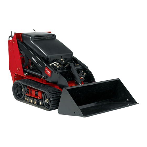
Sitework Systems TX525 compact utility loader. Sitework Systems TX 413 compact utility loader. Avoid injury from batteries... The TX525 loader and attachment operator’s manual contain safety information and operating tips for safe Think Safety First Battery acid is poisonous and can cause burns. Avoid operating practices. - Page 13 • Before disconnecting or performing any work on the hydraulic system, lower the loader arm/attachment to the ground and stop the engine so all pressure is relieved. • Be sure you understand a service procedure before working on the machine. Rev. 000 TX525 Service Manual...
-
Page 14: Specifications
Low idle Speed – 1600 rpm ± 50 rpm Oil Capacity 3.84 quarts (3.63 liters) with filter Fuel Tank 6 gallons (22.7 liters) Dimensions TX525 Narrow Track TX525 Wide Track Overall Length, without Bucket 70.7” (179.6cm) 70.7” (179.6cm) Overall Length, with Bucket 92”... -
Page 15: Periodic Maintenance Items
553 lbs. (250.8kg) (35% of tip per SAE J818) Speed 0 - 4.5 mph (0 - 7.2km/hr) forward 0 - 2 mph (0 - 3.2km/hr) reverse Weight 2001 lbs. (907.6kg) (traction unit only) 2127 lbs. (964.7kg) (w/TX bucket) Rev. 000 TX525 Service Manual... -
Page 16: Hydraulic System
Working Pressure: 3000 psi (206.8 bar) Dump Cylinder The Quick-Attach angle is controlled by a single hydraulic cylinder. Bore Size: 2.75” (7cm) Rod Size: 1.25” (3.2cm) Stroke: 7.75” (19.7cm) Working Pressure: 3000 psi (206.8 bar) TX525 Service Manual Rev. 000... -
Page 17: Hydraulic System Cont
The tracks are Kevlar reinforced, endless rubber rings with 28 internal drive lugs. The outer tread on the tracks is a turf-friendly S-shaped pattern with pitched crosscuts. Track Width: TX525 (Narrow Track) - 5.88” (14.9cm) TX525 (Wide Track) - 9.5” (24.13cm) Track Pitch: 3.45”... -
Page 18: Torque Specifications
Fastener Identification Recommended fastener torque values are listed in the following tables. For critical applications, as determined by Toro, either the recommended torque or a torque that is unique to the application is clearly identified and specified in the service manual. -
Page 19: Standard Torque For Dry, Zinc Plated, And Steel Fasteners (Inch Series)
The specific torque value should be determined based on the fastener size, the aluminum or base material strength, length of thread engagement, etc. Rev. 000 TX525 Service Manual ® TimeCutter Z Service Manual 2 - 5... -
Page 20: Standard Torque For Dry, Zinc And Steel Fasteners (Metric Series)
The specific torque value should be determined based on the fastener size, the aluminum or base material strength, length of thread engagement, etc. TX525 Service Manual Rev. 000 ® 2 - 6 TimeCutter... -
Page 21: Other Torque Specifications
All torque values are based on non- lubricated fasteners. Conversion Factors in-lb X 11.2985 - N-cm N-cm X - 0.08851 = in-lb ft-lb X 1.3558 = N-m N-cm X 0.73776 - ft-lb Rev. 000 TX525 Service Manual ® TimeCutter Z Service Manual 2 - 7... -
Page 22: Equivalents And Conversions
24.209 15/32 0.46875 11.906 31/32 0.96875 24.606 31/64 0.484375 12.303 63/64 0.984375 25.003 0.5000 12.700 1.000 25.400 1 mm = 0.03937 in. 0.001 in. = 0.0254 mm TX525 Service Manual Rev. 000 ® 2 - 8 TimeCutter Z Service Manual... -
Page 23: U.s. To Metric Conversions
Inch-pounds Kilogram-Centimeters 1.152144 Quarts Liters 0.9463 Liquid Volume Gallons Liters 3.785 3.785 Gallons/Minute Liters/Minute Liquid Flows Fahrenheit Celsius 1. Subtract 32° Temperature 2. Multiply by 5/9 ® TimeCutter Z Service Manual 2 - 9 2-10 Rev. 000 TX525 Service Manual... -
Page 24: Maintenance
• Check battery cable • Adjust track tension connections • Check tracks and road wheels • Check cooling system hoses • Complete all yearly • Check the alternator/fan maintenance procedures belt tension (refer to engine specified in the engine operator’s manual) operator’s manual • Check hydraulic lines for • Charge the battery and leaks, loose fittings, kinked disconnect the cables lines, loose mounting (storage only) supports, wear, weather and chemical deterioration Every 2 Years • Drain & clean the fuel tank • Check & adjust track tension • Check for dirt build-up in the chassis Important: Refer to your engine operator’s manual for additional maintenance procedures. Note: The hourmeter does not have service indicators. TX525 Service Manual Rev. 000... -
Page 25: Greasing The Traction Unit
MAINTENANCE Greasing the Traction Unit (4) are located on the right side (Fig. 0002). Grease all pivot joints every 8 operating hours and immediately after every washing. Grease Type: Lithium based NLGI2 1. Lower the loader arm and stop the engine. Remove the key from the ignition switch. 2. Clean the grease fittings with a rag. 3. Connect grease gun to each fitting and pump grease into the fittings until grease begins to ooze out (approximately 3 pumps). 4. Wipe any excess grease. There are 12 grease fittings on the TX525: Fig 0002 PICT-8729a (4) are located on the left side (Fig. 0001). (4) are located in the front on the quick attachment assembly and the front loader arm assembly (Fig. 0003). Fig 0001 PICT-8726a Fig 0003 PICT-8730 Rev. 000 TX525 Service Manual... -
Page 26: Maintaining The Road Wheels
They can also be removed by raising the unit off the ground. For safety reasons, make sure the frame of the unit is supported. Fig 0004 DSC-0821a 3. Remove the wheel bearing cap with seal (Fig. 0005). Fig 0006 DSC-0835a Fig 0005 DSC-0822 TX525 Service Manual Rev. 000... -
Page 27: Hydraulic Reservoir Tank
Check the hydraulic fluid level daily before the engine is first started and after every 25 operating hours. Fig 0008 PICT-8738 1. Remove the attachment, if one is installed. 2. Park the traction unit on a level surface, open the hood, raise the loader arm, install cylinder lock and 7. The fluid level should be between the marks on the fully retract the tilt cylinder. dipstick. If the level is low, add enough fluid to raise it to the proper level. 3. Stop the engine, remove the key, and and allow the engine to cool. 8. Install the cap on the filler neck. 4. Remove the LH side grill. 9. Install the RH side grill. 5. Clean the area around the filler neck of the hydraulic 10. Start the unit, remove the cylinder lock and lower the tank (Fig. 0007). loader arms. 11. Close the hood. Fig 0007 PICT-8731 Rev. 000 TX525 Service Manual... -
Page 28: Replacing The Hydraulic Filter
11. Raise the loader arm and install cylinder lock. 4. Place absorbant towels under the filter. 12. Stop the engine, remove the LH side grill, check the fluid level in the hydraulic tank (refer to “Checking 5. Remove the old filter (Fig. 0009). the Hydraulic Fluid” on page 3-4) and add fluid to raise the level to the mark on the dipstick. Do not over fill the tank. 13. Install LH side grill. 14. Install the rear access cover. 15. Remove cylinder lock and lower the loader arms. 16. Close the hood. Note: Dispose of used oil and filters at a certified recycling center. Fig 0009 Belt 013 TX525 Service Manual Rev. 000... -
Page 29: Changing The Hydraulic Fluid
Note: The hydraulic filter should be replaced when- ever the hydraulic oil is changed. 1. Position the traction unit on a level surface and open the hood. 2. Raise the loader arm, install the cylinder lock, stop the engine, and remove the key. 3. Allow the traction unit to cool completely. 4. Place a large drain pan (capable of holding 15 gallons) under the drain plug on the front of the traction unit (Fig. 0010). Fig 0011 PICT-8731 Fig 0010 PICT-8725 Fig 0012 PICT-8738 Rev. 000 TX525 Service Manual... -
Page 30: Checking The Hydraulic Lines
(Fig. 0014). 11. Start the engine, remove the cylinder lock, raise and lower the loader arm, then drive the unit forward and backward to purge air from the system and check for leaks. 12. Stop the engine. 13. Check the hydraulic fluid level and top it off if necessary. 14. Replace the hydraulic tank cap and dipstick (Fig. 0013). Fig 0014 PICT-8740 Fig 0013 PICT-8731 15. Install LH side grill. 16. Remove cylinder lock and lower the loader arms. 17. Close the hood. TX525 Service Manual Rev. 000... -
Page 31: Engine Servicing
MAINTENANCE Engine Servicing Oil Dipstick - check oil level daily (Fig. 0015). Fig 0017 PICT-8744 A. Oil fill C. Oil filter B. Oil dipstick Fig 0015 PICT-8741 • Change oil after the first 50 hrs then every 100 hrs 1, 2 Oil Drain (Fig. 0016 and Fig. 0017) • Oil Filter 200 hrs 1, 3 More often in dusty, dirty conditions. Change oil after the first 50 operating hours. For severe duty or rental applications, change every 100 operating hours. Oil type: Detergent diesel engine oil (API Service CH-4 or higher) Crankcase capacity: With filter 0.98 gallons (3.7 liters) Fig 0016 PICT-8914 Rev. 000 TX525 Service Manual... -
Page 32: Servicing The Cooling System
• Before each use or daily - Clean the radiator. coolant can escape and cause severe burns. • Every 100 hours - Check the cooling system • Do not remove the radiator cap when the hoses. engine is hot. Always allow the engine to cool at least 15 minutes or until the radiator cap • Yearly - Change the engine coolant. is cool enough to touch without burning your hand before removing the radiator cap. • Do not touch radiator and surrounding parts that are hot. • Use a rag when opening the radiator cap, and open the cap slowly to allow steam to escape. Cleaning Radiator The engine fan draws the air from the engine compart- ment and pushes the air through that hydraulic oil cooler and radiator. Remove any build up of debris on the oil cooler and radiator with compressed air. Fig 0018 PICT-8749 Engine Coolant If you need to add engine coolant, refer to “Checking, Adding & Bleeding the Engine Coolant” on page 4-138. Change the engine coolant yearly. Refer to “Changing Engine Coolant” on page 3-10. TX525 Service Manual Rev. 000... -
Page 33: Changing Engine Coolant
MAINTENANCE Changing Engine Coolant 4. Remove the breather from the breather tube (Fig. 0020). 1. Park the machine on a flat surface, open the hood and raise the loader arm. Lock the loader arm into position using the loader arm lock. 2. Turn the machine off and allow it to cool. 3. Remove the left and right hand side panels (Fig. 0019). Fig 0020 PICT-4946a 5. Remove the 4 bolts securing the grill assembly to the frame (Fig. 0021). Fig 0019 PICT-4945 Fig 0021 PICT-4953 3-10 Rev. 000 TX525 Service Manual... - Page 34 MAINTENANCE 6. Slide the grill assembly forward (Fig. 0022). 8. Remove the grill assembly taking care not to dam- age the hydraulic tank breather hose (Fig. 0024). Fig 0022 PICT-4955 Fig 0024 PICT-4961 7. Remove the 2 bolts and nuts securing the overflow 9. Inspect the foam seals on the inside of the grill as- tank bracket to the grill assembly (Fig. 0023). sembly. Replace if worn or damaged (Fig. 0025). Fig 0023 PICT-4959 Fig 0025 PICT-5138a TX525 Service Manual Rev. 000 3-11...
- Page 35 10. Place an absorbent towel under the oil cooler inlet 14. Using a 1-1/16” and a 1-1/8” wrench, remove the oil fitting located on the lower left hand corner of the oil cooler outlet line from the oil cooler outlet fitting (Fig. cooler. 0027). 11. Using a 1-1/16” and a 1-1/8” wrench, remove the oil cooler inlet line from the oil cooler inlet fitting (Fig. 0026). Fig 0027 PICT-4968a 15. Cap the hydraulic line and fitting so debris does not Fig 0026 PICT-4965 enter the system. 16. Using a 1/2” socket, remove the 3 bolts securing the 12. Cap the hydraulic line and fitting so debris does not radiator mount to the frame (Fig. 0028). enter the system. 13. Place an absorbent towel under the oil cooler outlet fitting located on the upper right hand corner of the oil cooler. Fig 0028 PICT-4969 3-12 Rev. 000 TX525 Service Manual...
- Page 36 MAINTENANCE 17. Remove the front radiator mount (Fig. 0029). 19. Slide a length of 5/16” hose onto the petcock drain. Place the other end of the hose into a drain pan. Open the petcock and remove the radiator cap to drain the anti-freeze (Fig. 0031). Fig 0029 PICT-4971 Fig 0031 PICT-4974 18. Tilt the radiator/oil cooler assembly forward and lift it out of the frame so that the petcock drain is above the frame (Fig. 0030). 20. Remove the drain hose and close the petcock. 21. Using a 17mm wrench, remove the engine block coolant drain plug (Fig. 0032). Fig 0030 PICT-4973 Fig 0032 PICT-8910 TX525 Service Manual Rev. 000 3-13...
-
Page 37: Changing Engine Coolant Assembly
Changing Engine Coolant Assembly 5. Using 1-1/16” and 1-1/8” wrenches, install the hy- draulic outlet line to the oil cooler outlet fitting (Fig. 0035). 1. Clean any debris around and under the radiator. 2. Using a 17mm wrench install the engine block coolant drain plug (Fig. 0033). Fig 0035 PICT-5126 Fig 0033 PICT-8910 6. Position the radiator mount into the frame (Fig. 0036). 3. Remove the drain hose and close the petcock. 4. Position the radiator/oil cooler assembly into the frame so it is on top of the foam seals and behind the 3 radiator mount holes (Fig. 0034). Fig 0036 PICT-5129 Fig 0034 PICT-5122 3-14 Rev. 000 TX525 Service Manual... - Page 38 MAINTENANCE 7. Loosely install 3 screws that will secure the radiator 9. Without moving the position of the radiator, slide the mount to the frame (Fig. 0037). radiator mount against the radiator and tighten the 3 radiator mount screws (Fig. 0039). Fig 0037 PICT-5131 Fig 0039 PICT-5137 8. Center the radiator and oil cooler assembly side to side in the frame so there is approximately a 1/8” 10. Position the grill onto the frame and route the breath- space between the fan shroud and the fan. Spin er tube in between the foam seals on the inner left the cooling fan. Ensure the fan does not come into side of the grill (Fig. 0040). contact with the fan shroud. Adjust the radiator side to side as necessary (Fig. 0038). Fig 0040 PICT-5139 Fig 0038 PICT-5135 TX525 Service Manual Rev. 000 3-15...
- Page 39 13. Install 2 bolts and nuts securing the overflow bottle the loader stops and the top of the grill sits on top assembly to the grill assembly (Fig. 0043). of the radiator. Leave the grill in a slightly forward position. The overflow tank mounting holes should be just beyond the right hand boss on top of the radiator assembly. This will allow the overflow bottle assembly to be installed (Fig. 0041). Fig 0043 PICT-5145 14. Slide the grill assembly back aligning the mounting holes with the holes in the frame. Loosely install 4 Fig 0041 PICT-5141a bolts securing the grill assembly to the frame and the 2 bolts and washers securing the grill to the radiator A. Overflow tank mounting holes (Fig. 0044). B. Right hand boss 12. Position the overflow tank bracket onto the grill assembly (Fig. 0042). Fig 0044 PICT-5146 Fig 0042 PICT-5143a 3-16 Rev. 000 TX525 Service Manual...
- Page 40 MAINTENANCE 15. Using a 1/2” socket, tighten the 4 bolts securing the New style (use flange head bolts): grill assembly to the frame (Fig. 0045). Fig 0047 PICT-5605 Fig 0045 PICT-5150 18. Position the breather tube under the grill and install 16. Check the cooling fan and shroud clearance. Adjust the breather (Fig. 0048). the position of the radiator if necessary. 17. Using a 9/16” socket, tighten the 2 bolts securing the radiator to the grill assembly (Fig. 0046 and Fig. 0047). Old style (use bolts and washers): Fig 0048 PICT-5157 Fig 0046 PICT-5604 TX525 Service Manual Rev. 000 3-17...
-
Page 41: Fuel System
Drain & Clean Fuel Tank Draining the fuel tank Service interval: Every 2 years. Replacing the fuel filter/water separator Service interval: Every 400 hours 1. Clean the area where the fuel filter/water separator mounts. Fig 0049 PICT-4945 2. Remove the fuel filter/water separator and clean the mounting surface. 28. Remove the cylinder lock and lower the loader arms. 3. Lubricate the gasket on the new fuel filter/water separator with clean oil. 29. Close the hood. 4. Install the fuel filter/water separator by hand until the 30. Purge air from the hydraulic system. Refer to “Purg- gasket contacts the mounting surface, then rotate it ing Air Procedure” on page 9-19. an additional 1/2 turn. 3-18 Rev. 000 TX525 Service Manual... -
Page 42: Fuel Tank Removal
MAINTENANCE Fuel Tank Removal 4. Using a 3/8” socket, remove the 6 screws that se- cure the left and right rear cover support panels to the tower assembly (3 screws per panel). Remove 1. Park the machine so that the tracks are resting on the panels (Fig. 0052). 2x4s. 2. Open the hood. Raise the loader arms, install the cylinder lock, stop the engine and remove the key. 3. Apply the parking brake. 3. Remove the rear access panel (Fig. 0051). Fig 0052 PICT-8934 5. Using 3/4” and 1/2” sockets, remove the 7 bolts and nuts securing the rear frame cover to the frame and fuel tank bracket. Remove the rear frame cover (Fig. 0053). Fig 0051 PICT-4505a Fig 0053 PICT-5381 TX525 Service Manual Rev. 000 3-19... - Page 43 MAINTENANCE 6. Remove the fuel tank bracket (Fig. 0054). 8. Mark the suction fuel line and tank fitting with an “S” and the return fuel line and tank fitting with an “R” (Fig. 0056): S - Fuel suction line R - Fuel return line Fig 0054 PICT-5625 7. Disconnect the two wires (black and orange) from Fig 0056 PICT-4263 the fuel sending unit located on the top of the fuel tank (Fig. 0055). 9. Slide the 2 fuel hose clamps down the fuel line away from the fuel tank fittings (Fig. 0057). Fig 0055 PICT-4262a Fig 0057 PICT-4264 3-20 Rev. 000 TX525 Service Manual...
-
Page 44: Fuel Tank Installation
MAINTENANCE Fuel Tank Installation 10. Slide the 2 fuel lines off the fuel tank fittings. Re- move the fuel tank (Fig. 0058). 1. Slide the 2 fuel lines onto the fuel tank fittings. In- stall the fuel tank (Fig. 0059). Fig 0058 PICT-4265 Fig 0059 PICT-4265 11. Remove the fuel cap and tip the fuel tank to dump any remaining fuel from the tank into a proper drain pan. 2. Slide the 2 fuel hose clamps up the fuel line to the fuel tank fittings (Fig. 0060). 12. Add approximately 1/2 gallon (2 liters) clean fuel to the tank and install fuel cap and slosh the fuel in the tank remove the fuel cap and dump fuel into a proper drain pan. Repeat process until the fuel tank is clean. Replace the fuel tank if the fuel tank does not become clean. Fig 0060 PICT-4264 TX525 Service Manual Rev. 000 3-21... - Page 45 3. Connect the two wires (black and orange) to the fuel 5. Install the fuel tank bracket nut and bolt (Fig. 0063). sending unit located on the top of the fuel tank (Fig. 0061). Fig 0063 PICT-5625 Fig 0061 PICT-4262a A. Orange wire (center B. Black wire (outside 6. Install the left and right rear cover support panels. terminal) terminal) Using a 3/8” socket, install the 6 screws that secure the left and right rear cover support panels to the tower assembly (3 screws per panel) (Fig. 0064). 4. Install the rear frame cover. Using 3/4” and 1/2” sockets, isntall the 7 bolts and nuts securing the rear frame cover to the frame and fuel tank bracket (Fig. 0062). Fig 0064 PICT-4256 Fig 0062 PICT-5381 3-22 Rev. 000 TX525 Service Manual...
- Page 46 MAINTENANCE 7. Install the rear access panel (Fig. 0065). 9. Change the fuel filter/water separator and the inline fuel filter (if applicable). 10. Install the right hand side panel. 11. Remove the loader lock and lower the loader arm. 12. Close the hood. 13. Add fuel to the tank and install cap. 14. Release the parking brake. 15. Drive the unit off the 2x4’s. Fig 0065 PICT-4505a 8. Remove the right hand side panel (Fig. 0066). Fig 0066 PICT-4942 TX525 Service Manual Rev. 000 3-23...
-
Page 47: Replacing The In-Line Fuel Filter (Serial Numbers 280000500 & Higher)
Replacing the In-Line Fuel Filter (Serial numbers 280000500 & higher) Service Interval: • Every 200 hours - replace the primary air filter Replace the in-line filter when damage, contamination or debris is present. • Every 600 hours - replace the secondary air filter 1. Locate the in-line fuel filter (Fig. 0067) and note the * More often in dusty, dirty conditions direction of flow arrow on the side of the in-line filter. Fig 0068 PICT-8748 Fig 0067 PICT-8751 2. Open the clamps on each end of the in-line filter and slide the hoses off of it. Discard the filter. 3. Slide the hoses over the end of a new filter, ensuring that the arrow on the filter is pointing in the same direction as the one on the old filter. 4. Secure the hoses with the hose clamps. 3-24 Rev. 000 TX525 Service Manual... -
Page 48: Fuse Block
5. Check the fuses. Replace as necessary (Fig. 0069). Replace the belt if you find any signs of wear, cracks, or damage or yearly, whichever comes first (Fig. 0070). Note: Fuses can be removed to check continuity. The test meter should read less than 1 ohm. Fig 0070 PICT-8756 Fig 0069 PICT-8753 A. 30 amp = Main circuit B. Empty C. 10 amp = Control panel / Relay D. Open position for optional accessories TX525 Service Manual Rev. 000 3-25... -
Page 49: Alternator/Fan Belt
MAINTENANCE Alternator/Fan Belt 4. Replace fan belt if it is worn or damaged. Replace the pulley if the belt groove is worn excessively (Fig. 0072). Fan Belt Tension: Deflects 0.28 to 0.35” (7 to 9mm) when the belt is pressed in the middle of the span (Fig. 0071). Fig 0072 fig. 3EEABAB1P018A A. New belt B. Worn belt Fig 0071 fig. 3EEABAB1P017B A. Deflection 1. Stop the engine and remove the key. 2. Apply moderate thumb pressure to belt between the alternator and crankshaft pulleys. 3. If tension is incorrect, loosen the alternator mounting bolts and, using a lever placed between the alternator and the engine block, pull the alternator out until the deflection of the belt falls within acceptable limits. 3-26 Rev. 000 TX525 Service Manual... -
Page 50: Track Inspection
(7cm) Replace the track if it is torn or cut and/or the tread is worn (Fig. 0073). Track Tread (cracked/damaged/worn): Fig 0075 track install #3 A. Tension nut B. Tensioner arm Use an alignment tool (Toro p/n: 110-0069) to align the track guide to drive wheel prior to installing a new track, or if the track lugs display abnormal wear or gouging in use. Fig 0073 PICT-3377 Replace the track if most of the center lugs are gouged or worn 1/2” (1.27cm) on either side or a combination of Check the center lugs daily for gouging and excessive both sides. Nominal lug width is 2 1/2” (6.35cm) at the wear (Fig. 0074). base of the lug. Center Lug (damaged/worn): Refer to “Track Guide Alignment” on page 7-3. Refer to “Track Replacement”: • “Wide Track Removal on page 7-68. • “Narrow Track Removal” on page 7-72. Fig 0074 PICT-3378 TX525 Service Manual Rev. 000 3-27... -
Page 51: Battery Maintenance
Fig 0076 PICT-8762 battery plates. State of Charge Specific Gravity Voltage 12V Batteries are available in two basic versions; mainten- 100% 1.265 12.7 ance free and maintenance type. 1.225 12.4 1.190 12.2 With either type of battery it is important to have clean 1.155 12.0 terminals and tight cable connections to the battery posts. Escaping gases from the battery causes corrosion Discharged 1.120 11.9 at the terminals and other metal parts. The battery should be cleaned periodically using a baking soda and water mix; a couple of tablespoons baking soda to a pint (.5 liter) of water. 3-28 Rev. 000 TX525 Service Manual... -
Page 52: Testing
MAINTENANCE Battery Testing You must first have the battery fully charged prior to any test. The surface charge must be removed before testing. To remove surface charge the battery must experience a load of 20 amps for 3 plus minutes. Battery specific gravity can be measured by using a hydrometer or a refractometer. Load testing removes amps from a battery much like start-ing an engine would. The battery may have a label with the amp load for testing and/or a CCA Cold Cranking Amp rating. The load test number is 1/2 of the CCA rating. For example, a 500 CCA battery would load test at 250 amps for 15 seconds. A load test can only be performed if the battery is near or at full charge. If you have a maintenance free battery, the only ways to test are with a digital voltmeter and/or a load test. The reading on the digital voltmeter should be the voltage shown in the previous table. If you have voltage readings in the 10.5 volts range on a charged battery, that indicates a shorted cell. Batteries used in equipment stored for some portion of the year can discharge and sulfation between the battery plates can occur and shorten the life of the battery. TX525 Service Manual Rev. 000 3-29... -
Page 53: Special Tools
MAINTENANCE Special Tools Spring Removal Tool (Fig. 0079) - Toro P/N: 92-5771 For tool use example see page 7-6, step 10. Listed below are the special tools used in some of the procedures in this manual. To order these tools, contact the Toro Company. Track Alignment Tool (Fig. 0077) - Toro P/N: 110-0069 For tool use example see page 7-3. Fig 0079 PICT-4131b Fig 0077 PICT-4139a Puller Kit (Fig. 0078) - Toro P/N: 112-2557 For tool use example see page 7-28, step 37. Fig 0078 PICT-4143b 3-30 Rev. 000 TX525 Service Manual... -
Page 54: Engine
Protect the inner diameter of seals and orings from damage during assembly by covering the shaft machined features with 5. Remove the breather from the breather tube (Fig. plastic wrap or equivalent. 0081). 1. Park the machine on a flat surface and raise the hood. 2. Raise the loader arm and lock the loader arm into position using the loader arm lock. 3. Turn the machine off and remove the key. Allow the machine to cool. Fig 0081 PICT-4946a TX525 Service Manual Rev. 000... - Page 55 ENGINE 6. Remove the 4 bolts securing the grill assembly to 8. Remove the 2 bolts and nuts securing the overflow the frame (Fig. 0082). tank bracket to the grill assembly (Fig. 0084). Fig 0082 PICT-4953 Fig 0084 PICT-4959 7. Slide the grill assembly forward (Fig. 0083). 9. Remove the grill assembly taking care not to dam- age the hydraulic tank breather hose (Fig. 0085). Fig 0083 PICT-4955 Fig 0085 PICT-4961 Rev. 000 TX525 Service Manual...
- Page 56 15. Using a 1-1/16” and a 1-1/8” wrench, remove the oil cooler outlet line from the oil cooler outlet fitting (Fig. 0088). Fig 0086 PICT-5138a 11. Place an absorbent towel under the oil cooler inlet fitting located on the lower left hand corner of the oil Fig 0088 PICT-4968a cooler. 12. Using a 1-1/16” and a 1-1/8” wrench, remove the oil cooler inlet line from the oil cooler inlet fitting (Fig. 16. Cap the hydraulic line and fitting so debris does not 0087). enter the system. 17. Using a 1/2” socket, remove the 3 bolts securing the radiator mount to the frame (Fig. 0089). Fig 0087 PICT-4965 Fig 0089 PICT-4969 13. Cap the hydraulic line and fitting so debris does not enter the system. TX525 Service Manual Rev. 000...
- Page 57 ENGINE 18. Remove the front radiator mount (Fig. 0090). 20. Slide a length of 5/16” hose onto the petcock drain. Place the other end of the hose into a drain pan. Open the petcock and remove the radiator cap to drain the coolant (Fig. 0092). Fig 0090 PICT-4971 Fig 0092 PICT-4974 19. Tilt the radiator/oil cooler assembly forward and lift it out of the frame so that the petcock drain is above the frame (Fig. 0091). 21. Remove the drain hose and close the petcock. 22. Loosen the 2 hose clamps securing the 2 radiator hoses to the left hand side of the radiator (Fig. 0093). Fig 0091 PICT-4973 Fig 0093 PICT-4975 Rev. 000 TX525 Service Manual...
- Page 58 ENGINE 23. Slide the 2 radiator hoses off the left hand side of the 25. Remove the radiator/oil cooler assembly from the radiator (Fig. 0094). frame (Fig. 0096). Fig 0094 PICT-4978 Fig 0096 PICT-4980 24. Loosen the hose clamp securing the radiator hose to 26. Cap the inlet and outlet flanges and fittings so that the right hand side of the radiator. Slide the radiator debris does not enter into the cooling system. hose off the right hand side of the radiator (Fig. 0095). 27. To repair or replace only the oil cooler, continue on to “Oil Cooler Removal”. To repair or replace the radiator, refer to “Radiator Removal” on page 4-10. Fig 0095 PICT-4979 TX525 Service Manual Rev. 000...
-
Page 59: Oil Cooler Removal
ENGINE Oil Cooler Removal 3. Remove the fan shroud from the radiator/oil cooler assembly (Fig. 0099). 1. Remove the 4 bolts, 2 washers and 4 nuts securing the fan shroud to the radiator/oil cooler assembly (Fig. 0097). Fig 0099 PICT-5061 Fig 0097 PICT-5058 4. Using a 1/2” wrench, remove the 2 bolts, washers and lock washers securing the oil cooler to the top side of the radiator (Fig. 0100). 2. Remove the backing plate from the radiator/oil cooler assembly (Fig. 0098). Fig 0100 PICT-5062 Fig 0098 PICT-5060 Rev. 000 TX525 Service Manual... -
Page 60: Oil Cooler Installation
ENGINE 5. Using a 1/2” wrench, loosen the other 2 bolts, wash- 7. Inspect the oil cooler. Repair or replace. ers and lock washers securing the oil cooler to the bottom side of the radiator (Fig. 0101). 8. Inspect the foam strips on the radiator. If worn or damaged, replace. Oil Cooler Installation 1. Clean all dirt and debris from the radiator assembly. 2. Position the oil cooler onto the radiator by sliding the oil cooler mounting flange under the 2 flat washers on the bottom side of the radiator (Fig. 0103). Fig 0101 PICT-5064 6. Remove the oil cooler from the radiator by sliding the oil cooler flange out from underneath the 2 bolts (Fig. 0102). Fig 0103 PICT-5066 Fig 0102 PICT-5065 TX525 Service Manual Rev. 000... - Page 61 ENGINE 3. Loosely install the 2 bolts, lockwashers and washers 5. Position the fan shroud onto the radiator/oil cooler securing the opposite oil cooler mounting flange to assembly (Fig. 0106). the top side of the radiator (Fig. 0104). Fig 0106 PICT-5073 Fig 0104 PICT-5068 6. Position the backing plate onto shroud (Fig. 0107). 4. Center the oil cooler onto the radiator (Fig. 0105) and progressively tighten each of the 4 bolts to evenly secure the oil cooler to the radiator. Fig 0107 PICT-5085 Fig 0105 PICT-5084a Rev. 000 TX525 Service Manual...
- Page 62 ENGINE 7. Loosely install 2 bolts and nuts securing the backing 9. Tighten the 4 bolts securing the fan shroud to the plate and fan shroud to the radiator/oil cooler as- radiator/oil cooler assembly (Fig. 0110). sembly (Fig. 0108). Fig 0110 PICT-5089a Fig 0108 PICT-5086 10. Install the radiator/oil cooler assembly into the 8. Loosely install 2 bolts, washers and nuts securing machine. Refer to “Radiator & Oil Cooler Assembly the fan shroud to the radiator/oil cooler assembly Installation” on page 4-15. (Fig. 0109). Fig 0109 PICT-5087 TX525 Service Manual Rev. 000...
-
Page 63: Radiator Removal
ENGINE Radiator Removal 3. Remove the fan shroud from the radiator/oil cooler assembly (Fig. 0113). 1. Remove the 4 bolts, 2 washers and 4 nuts securing the fan shroud to the radiator/oil cooler assembly (Fig. 0111). Fig 0113 PICT-5073 Fig 0111 PICT-5081a 4. Using a 1/2” wrench, remove the 2 bolts, washers and lock washers securing the oil cooler to the top side of the radiator (Fig. 0114). 2. Remove the backing plate from the radiator/oil cooler assembly (Fig. 0112). Fig 0114 PICT-5072a Fig 0112 PICT-5074 4-10 Rev. 000 TX525 Service Manual... - Page 64 ENGINE 5. Using a 1/2” wrench, loosen the 2 bolts securing 7. Remove the 2 oil cooler mounting bolts, lock wash- the bottom side of the oil cooler to the radiator (Fig. ers and washers that are remaining in the radiator 0115). (Fig. 0117). Fig 0115 PICT-5066 Fig 0117 PICT-5090 6. Remove the oil cooler from the radiator (Fig. 0116). 8. Remove the radiator bracket (Fig. 0118). Fig 0116 PICT-5065 Fig 0118 PICT-5092a TX525 Service Manual Rev. 000 4-11...
-
Page 65: Radiator Installation
ENGINE Radiator Installation 9. Inspect the foam seals on the radiator bracket. Re- place if worn or damaged (Fig. 0119 and Fig. 0120). 1. Apply 2 foam seals onto the new radiator. Locate as shown (Fig. 0121 and Fig. 0122). Right side: Fig 0119 PICT-5093a Fig 0121 PICT-5095a Left side: Fig 0120 PICT-5094a 10. Inspect the radiator. Repair or replace. Fig 0122 PICT-5096 4-12 Rev. 000 TX525 Service Manual... - Page 66 ENGINE 2. Slide the radiator bracket onto the radiator so that 4. Position the oil cooler onto the radiator by sliding the mounting holes in the flanges line up (Fig. 0123). the mounting flange onto the 2 bolts so that the mounting flange is located between the radiator and the flat washers (Fig. 0125). Fig 0123 PICT-5098a Fig 0125 PICT-5100 3. Thread 2 bolts, lockwashers and washers into the holes located on the bottom mounting flange (Fig. 5. Loosely install 2 bolts, lockwashers and flat washers 0124). through the top mounting flange of the oil cooler and into the radiator (Fig. 0126). Fig 0124 PICT-5099 Fig 0126 PICT-5101 TX525 Service Manual Rev. 000 4-13...
- Page 67 ENGINE 6. Center the oil cooler onto the radiator (Fig. 0127) 8. Position the backing plate onto the fan shroud (Fig. and progressively tighten each of the 4 bolts to 0129). evenly secure the oil cooler to the radiator. Fig 0129 PICT-5107 Fig 0127 PICT-5105a 9. Loosely install 2 bolts and nuts securing the backing 7. Position the fan shroud onto the radiator/oil cooler plate and fan shroud to the radiator/oil cooler as- sembly (Fig. 0130). assembly (Fig. 0128). Fig 0130 PICT-5108 Fig 0128 PICT-5106 4-14 Rev. 000 TX525 Service Manual...
-
Page 68: Radiator & Oil Cooler Assembly Installation
ENGINE 10. Loosely install 2 bolts, washers and nuts securing 12. Install the radiator/oil cooler assembly into the ma- the fan shroud to the radiator/oil cooler assembly chine. Refer to “Radiator and Oil Cooler Assembly (Fig. 0131). Installation” following. Radiator & Oil Cooler Assembly Installation 1. Inspect the foam seals located inside the frame. Re- place if worn or damaged (Fig. 0133). Fig 0131 PICT-5109 11. Tighten the 4 bolts securing the fan shroud to the radiator/oil cooler assembly (Fig. 0132). Fig 0133 PICT-5110 Fig 0132 PICT-5111a TX525 Service Manual Rev. 000 4-15... - Page 69 ENGINE 2. Position the radiator/oil cooler assembly into the 5. Slide the left radiator hoses (top hoses) onto the 2 frame so it is on top of the foam seals and behind radiator flanges (Fig. 0136). the 3 radiator mount holes (Fig. 0134). Fig 0136 PICT-5124 Fig 0134 PICT-5122 6. Slide the hose clamps into position with the tighten- 3. Remove the protective caps from the inlet and outlet ing screw heads facing outward as shown. This will flanges and fittings. allow access to these tightening screws through the grill assembly when it is in position. Tighten the hose 4. Using 1-1/16” and 1-1/8” wrenches, install the hy- clamps (Fig. 0137). draulic oil inlet line to the oil cooler inlet fitting (Fig. 0135). Fig 0137 PICT-5125 Fig 0135 PICT-4965 4-16 Rev. 000 TX525 Service Manual...
- Page 70 ENGINE 7. Using 1-1/16” and 1-1/8” wrenches, install the hy- 9. Slide the hose clamp into position with the tightening draulic outlet line to the oil cooler outlet fitting (Fig. screw head facing outward as shown. This will allow 0138). access to the tightening screw through the grill as- sembly when it is in position. Tighten the hose clamp (Fig. 0140). Fig 0138 PICT-5126 Fig 0140 PICT-5128 8. Slide the radiator inlet hose (bottom hose) onto the radiator flange (Fig. 0139). 10. Position the radiator mount into the frame (Fig. 0141). Fig 0139 PICT-5127 Fig 0141 PICT-5129 TX525 Service Manual Rev. 000 4-17...
- Page 71 ENGINE 11. Loosely install 3 screws that will secure the radiator 13. Without moving the position of the radiator, slide the mount to the frame (Fig. 0142). radiator mount against the radiator and tighten the 3 radiator mount screws (Fig. 0144). Fig 0142 PICT-5131 Fig 0144 PICT-5137 12. Center the radiator and oil cooler assembly side to 14. Position the grill onto the frame and route the breath- side in the frame so there is approximately a 1/8” er tube in between the foam seals on the inner left (3.2mm) space between the fan shroud and the fan. side of the grill (Fig. 0145). Spin the cooling fan. Ensure the fan does not come into contact with the fan shroud. Adjust the radiator side to side as necessary (Fig. 0143). Fig 0145 PICT-5139 Fig 0143 PICT-5135 4-18 Rev. 000 TX525 Service Manual...
- Page 72 Fig 0148 PICT-5145 18. Slide the grill assembly back aligning the mounting holes with the holes in the frame. Loosely install 4 Fig 0146 PICT-5141a bolts securing the grill assembly to the frame and the 2 bolts and washers securing the grill to the radiator A. Overflow tank mounting holes (Fig. 0149). B. Right hand boss 16. Position the overflow tank bracket onto the grill assembly (Fig. 0147). Fig 0149 PICT-5146 A. 4 Grill assembly-to-frame bolts B. 2 Grill assembly-to-radiator bolts and washers Fig 0147 PICT-5143a TX525 Service Manual Rev. 000 4-19...
- Page 73 ENGINE 19. Using a 1/2” socket, tighten the 4 bolts securing the TX525, serial #280000001 & higher, use flange head grill assembly to the frame (Fig. 0150). bolts: Fig 0150 PICT-5150 Fig 0152 PICT-5605 20. Check the cooling fan and shroud clearance. Adjust 22. Position the breather tube under the grill and install the position of the radiator if necessary. the breather (Fig. 0153). 21. Using a 9/16” socket, tighten the 2 bolts securing the radiator to the grill assembly (Fig. 0151 and Fig. 0152). TX525, serial #270000001 - 270999999, use bolts and washers: Fig 0153 PICT-5157 Fig 0151 PICT-5604 4-20 Rev. 000 TX525 Service Manual...
-
Page 74: Muffler Assembly & Air Cleaner Assembly Removal
Assembly Removal Glow Plug, Fuel Injector Access • To service the three glow plugs on the top side of the engine, the muffler must be removed. • To service #1 cylinder fuel infector the air cleaner must be removed. Fig 0154 PICT-3259 • To service #2 and #3 cylinder fuel injector the muffler must be removed. Muffler Removal 1. Position the traction unit on a flat surface. 2. Open the hood. 3. Raise loader arms approximately 4” (10cm). Lock the loader arm into position using the loader arm lock. 4. Remove right and left side panels. Fig 0155 PICT-3261 TX525 Service Manual Rev. 000 4-21... - Page 75 ENGINE 6. Using a 1/2” wrench and 1/2” socket combination, 8. Using a 13mm socket combination, remove the 4 remove the bolt and nut securing the bottom of the bolts and washers from the muffler and exhaust muffler to the rear muffler bracket (Fig. 0156). manifold flange (Fig. 0158). Fig 0156 PICT-3263 Fig 0158 PICT-3266 7. Using a 1/2” socket combination, remove the bolts 9. Remove the muffler assembly (Fig. 0159). securing the muffler to the front muffler bracket (Fig. 0157). Fig 0159 PICT-3268 Fig 0157 PICT-3265 4-22 Rev. 000 TX525 Service Manual...
-
Page 76: Air Cleaner Assembly Removal
Important: Keep the air cleaner assembly away from the exhaust manifold area. Fig 0160 PICT-3271 Air Cleaner Assembly Removal Fig 0162 PICT-5334 1. Using a 13mm socket, remove the 2 bolts and washers securing the air cleaner bracket assembly to the engine block (Fig. 0161). For testing and service of the glow plugs, refer to the Kubota Service manual “Kubota D722/D902 Tier 2 Diesel Engine Service Manual” (Toro Form No. 492- 4796) (Fig. 0163). Fig 0161 PICT-5232 Fig 0163 PICT-5337 TX525 Service Manual Rev. 000 4-23... -
Page 77: Air Cleaner Assembly & Muffler Assembly Installation
ENGINE Air Cleaner Assembly & Muffler For testing and service of the injectors, refer to the Kubota Service manual “Kubota D722/D902 Tier 2 Assembly Installation Diesel Engine Service Manual” (Toro Form No. 492- 4796) (Fig. 0164). Air Cleaner Assembly Installation 1. Position the air cleaner so the mounting bracket holes align with the mounting holes in the engine block. Using a 13mm socket, install 2 new bolts and washers securing the air cleaner assembly to the engine block (Fig. 0165). Fig 0164 PICT-5252 Fig 0165 PICT-5232 2. Torque the 2 bolts to 19 + 2 ft-lbs. (25.7 + 2.7 Nm) (Fig. 0166). Fig 0166 PICT-5335 4-24 Rev. 000 TX525 Service Manual... -
Page 78: Muffler Installation
ENGINE Muffler Installation 3. Position the muffler assembly and thread the pre- viously inserted bolt and washer into the exhaust manifold (Fig. 0169). 1. Ensure the exhaust gasket is in place (Fig. 0167). Fig 0169 PICT-3268 Fig 0167 PICT-3270 4. Loosely install the remaining 3 bolts and washers on 2. To aid in the installation process, insert a bolt and the muffler and exhaust manifold flange (Fig. 0170). washer into the right front position on the muffler flange (Fig. 0168). Fig 0170 PICT-3266 Fig 0168 PICT-3272 TX525 Service Manual Rev. 000 4-25... - Page 79 ENGINE 5. Loosely install the bolts on the front muffler bracket 7. Tighten the bolts on both the rear and front muffler (Fig. 0171). brackets. 8. Tighten and torque the exhaust manifold bolts to 28 ft-lbs. (38 Nm) (Fig. 0173). Fig 0171 PICT-3265 Fig 0173 PICT-3274 6. Using a 1/2” wrench and 1/2” socket combination, install and tighten the bolt and nut securing the bottom of the muffler to the rear muffler bracket (Fig. 0172). 9. Position and tighten the air intake hose clamp to the air filter assembly (Fig. 0174). Fig 0172 PICT-3263 Fig 0174 PICT-3259 10. Replace the right and left side panels. 4-26 Rev. 000 TX525 Service Manual...
-
Page 80: Alternator Replacement
ENGINE Alternator Replacement 6. Using a 1/2” wrench, disconnect the negative battery cable from the battery (Fig. 0176). Alternator Removal 1. Park the machine on a flat surface. 2. Raise the hood. 3. Raise the loader arm. Lock the loader arm into position using the loader arm lock. 4. Turn the machine off and remove the key. Allow the machine to cool. 5. Remove the rear access panel (Fig. 0175). Fig 0176 PICT-5158 7. Remove the left hand side panel (Fig. 0177). Fig 0175 PICT-4505a Fig 0177 PICT-4945 TX525 Service Manual Rev. 000 4-27... -
Page 81: Alternator Mounting Styles
ENGINE Alternator Mounting Styles TX525 22319 #270000556 - 270000720 22320 #270000712 - 270000885 22333 #270000423 - 270000446 The three methods of attaching the alternator are illus- 22334 #270000427 - 270000436 trated and described below. The engine gear case housing flange is threaded and fit with brackets (Fig. 0179). TX525 22319 #270000001 - 270000555 22320 #270000001 - 270000711 22333 #270000001 - 270000422 22334 #270000001 - 270000426 The engine gear case housing flange is threaded (Fig. 0178). Fig 0179 PICT-9354 TX525 22319 #270000721 & higher 22320 #270000886 & higher 22333 #270000447 & higher Fig 0178 PICT-5564 22334 #270000437 & higher The engine gear case housing flange is not threaded (not pictured). 4-28 Rev. 000 TX525 Service Manual... - Page 82 ENGINE 8. Remove the boot from the terminal. Using a 10mm 10. Remove the positive battery cable terminal from the socket, remove the nut securing the positive cable to alternator terminal (Fig. 0182). the alternator terminal (Fig. 0180). Fig 0182 PICT-5164 Fig 0180 PICT-5161 11. Unplug the harness connector from the alternator (Fig. 0183). 9. Remove the washer from the alternator terminal (Fig. 0181). Fig 0183 PICT-5165 Fig 0181 PICT-5162 TX525 Service Manual Rev. 000 4-29...
- Page 83 ENGINE 12. Using a 12mm socket, remove the flange nut secur- 14. Slide the threaded hex spacer out of the dipstick ing the hex spacer to the dipstick (Fig. 0184). bracket (Fig. 0186). Fig 0184 PICT-5170 Fig 0186 PICT-5175 13. Using a 13mm socket and a 9/16” wrench on the 15. Remove the mounting bolt, lock washer and washer hex spacer, loosen the alternator mounting bolt, (Fig. 0187). lockwasher and flat washer securing the alternator to the engine block. Loosen the bolt enough to free the hex spacer (Fig. 0185). Fig 0187 PICT-5176 Fig 0185 PICT-5171 4-30 Rev. 000 TX525 Service Manual...
- Page 84 ENGINE 16. Using a 12mm socket, support the alternator and 18. Remove the belt from the alternator pulley (Fig. remove the alternator belt tensioning bolt and lock- 0190). washer (Fig. 0188). Fig 0190 PICT-5178 Fig 0188 PICT-5166 19. Remove the alternator from the engine (Fig. 0191). 17. Remove the alternator belt guard (Fig. 0189). Fig 0191 PICT-5179 Fig 0189 PICT-5177 TX525 Service Manual Rev. 000 4-31...
-
Page 85: Alternator Installation
ENGINE Alternator Installation 20. Remove the collar from the alternator (Fig. 0192). 1. Slide the collar into the mounting flange on the alternator (Fig. 0194). Fig 0192 PICT-5180a Fig 0194 PICT-5180av 21. To service the alternator, refer to “Alternator Assembly Teardown” on page 4-153 (Fig. 0193). 2. Position the alternator up to the engine block (Fig. 0195). Fig 0193 PICT-5181a Fig 0195 PICT-5179 4-32 Rev. 000 TX525 Service Manual... - Page 86 ENGINE 3. Route the alternator belt around the alternator pulley 5. Using a 12mm socket, loosely install the alternator (Fig. 0196). belt tensioning bolt and lockwasher (Fig. 0198). Fig 0196 PICT-5178 Fig 0198 PICT-5166 4. Position the alternator belt guard up to the slotted 6. Loosely install the alternator mounting bolt, lock bracket (Fig. 0197). washer and washer through the belt guard, alterna- tor, coller and into the alternator mounting flange (Fig. 0199). Fig 0197 PICT-5177 Fig 0199 PICT-5176 TX525 Service Manual Rev. 000 4-33...
- Page 87 ENGINE 7. Position the threaded hex spacer into the dipstick 9. Using a 13mm socket and a 9/16” wrench, tighten bracket and align it with the alternator mounting the alternator mounting bolt, lockwasher and flat flange (Fig. 0200). washer securing the alternator to the engine block and threaded hex spacer (Fig. 0202). Fig 0200 PICT-5175 Fig 0202 PICT-5188 8. Apply tension to the alternator belt and tighten the 10. Using a 12mm socket, install a flange nut onto the top alternator mounting bolt (Fig. 0201). hex spacer securing it to the dipstick (Fig. 0203). Fig 0201 PICT-5565 Fig 0203 PICT-5170 4-34 Rev. 000 TX525 Service Manual...
- Page 88 ENGINE 11. Tension the alternator belt. Refer to “Alternator/Fan 14. Slide a washer onto the alternator terminal (Fig. Belt” on page 3-26. 0206). 12. Plug the harness connector into the alternator (Fig. 0204). Fig 0206 PICT-5162 Fig 0204 PICT-5165 15. Using a 10mm socket, install a nut securing the positive battery cable to the alternator terminal (Fig. 0207). Slide the boot onto the terminal. 13. Slide the positive battery cable terminal onto the alternator terminal (Fig. 0205). Fig 0207 PICT-5161 Fig 0205 PICT-5164 TX525 Service Manual Rev. 000 4-35...
- Page 89 ENGINE 16. Install the left hand side panel (Fig. 0208). 18. Install the rear access panel (Fig. 0210). Fig 0210 PICT-4505a Fig 0208 PICT-4945 19. Lower the loader arm. 17. Using a 1/2” wrench, connect the negative battery cable to the battery (Fig. 0209). 20. Lower the hood. Fig 0209 PICT-5158 4-36 Rev. 000 TX525 Service Manual...
-
Page 90: Checking The Alternator Belt Tension
Cooling Fan Replacement Checking the Alternator Belt Tension Cooling Fan Removal 1. Remove the radiator and oil cooler assembly. Refer to “Radiator & Oil Cooler Assembly Removal on page 4-1. 2. Using a 7/16” socket, remove the 4 bolts and lock- washers securing the cooling fan to the fan mount spacer (Fig. 0212). Fig 0211 fig. EEAB...17B A. .28 to 0.35” (7.0 to 9.0mm) 1. Measure the deflection (A) by depressing the belt halfway between the fan drive pulley and alternator pulley at the specified force of 22 lbs. (98 N, 10kgf). 2. If the measurement is not within the factory specifi- Fig 0212 PICT-5112a cations, loosen the alternator mounting screws and relocate the alternator to adjust and re-tighten the mounting screws. TX525 Service Manual Rev. 000 4-37... -
Page 91: Cooling Fan Installation
ENGINE 3. Slide the cooling fan off the fan mount spacer (Fig. 5. Remove the fan mount spacer (Fig. 0215). 0213). Fig 0215 PICT-5115 Fig 0213 PICT-5113a Cooling Fan Installation 4. Secure the flywheel so that it can not turn. Use a 6mm Allen socket to remove the 3 bolts securing the 1. Apply thread locking compound to the fan mount fan mount spacer to the engine coupler (Fig. 0214). spacer mounting bolts (Fig. 0216). Fig 0214 PICT-5114 Fig 0216 PICT-5116a 4-38 Rev. 000 TX525 Service Manual... - Page 92 ENGINE 2. Position the fan mount spacer to the engine coupler 4. Torque the 3 bolts to 19 + 2 ft-lbs. (25.7 + 2.7 Nm) (Fig. 0217). (Fig. 0219). Fig 0217 PICT-5115 Fig 0219 PICT-5117 3. Secure the flywheel so that it can not turn. Use a 5. Slide the cooling fan onto the fan mount spacer (Fig. 6mm Allen socket to install the 3 bolts securing the 0220). fan mount spacer to the engine coupler (Fig. 0218). Fig 0220 PICT-5113a Fig 0218 PICT-5114 TX525 Service Manual Rev. 000 4-39...
-
Page 93: Flywheel Replacement
6. Using a 7/16” socket, install 4 bolts and lockwashers securing the cooling fan to the fan mount spacer (Fig. 0221). Flywheel Removal 1. Remove the tandem pump assembly from the pump mount. Refer to “Hydraulic Tandem Pump Removal” on page 6-30. 2. Using a 13mm socket, remove the 4 bolts securing the pump mount to the engine housing (Fig. 0223). Fig 0221 PICT-5112a 7. Torque the 4 bolts to 100 + 10 in-lbs. (11.3 + 1.1 Nm) (Fig. 0222). Fig 0223 PICT-4863 3. Remove the pump mount (Fig. 0224). Fig 0222 PICT-5118a 8. Install the radiator and oil cooler assembly. Refer to “Radiator & Oil Cooler Assembly Installation on page 4-15. Fig 0224 PICT-4861 4-40 Rev. 000 TX525 Service Manual... - Page 94 ENGINE 4. Remove the hairpin cotter from the hood prop rod 6. Using a 1/2” wrench, remove the 2 lower heat shield (Fig. 0225). screws (Fig. 0227). Fig 0225 Belt 001 Fig 0227 Belt 002 5. Support the hood and remove the prop rod (Fig. 7. Using a 3/16” Allen wrench, remove the 2 upper heat 0226). shield screws (Fig. 0228). Fig 0226 Belt 003 Fig 0228 Belt 004 TX525 Service Manual Rev. 000 4-41...
- Page 95 ENGINE 8. Remove the heat shield (Fig. 0229). 10. Remove the belt from the right and left hydraulic traction pump pulleys (Fig. 0231). Fig 0229 Belt 005 Fig 0231 Belt 008 9. Using a spring tool (Toro p/n 92-5771), remove the 11. Remove the left hand side grill (Fig. 0232). idler spring from its post (Fig. 0230). Fig 0232 PICT-4945 Fig 0230 Belt 007 4-42 Rev. 000 TX525 Service Manual...
- Page 96 ENGINE 12. Remove the drive belt from around the engine pulley 14. Using a 6mm Allen socket, remove the 5 bolts secur- (Fig. 0233). ing the engine pulley to the flywheel (Fig. 0235). Fig 0233 PICT-4862 Fig 0235 PICT-4856 13. Secure the flywheel to keep it from turning. You 15. Remove the engine pulley (Fig. 0236). can do this by sliding a length of 5/16” diameter rod stock in between the fan mount pulley and fan mount spacer. The rod stock should be inserted so it runs on top of the fan mount pulley screw. The rod stock should be at least 16” (40.6cm) long so that it rests on the left hand loader arm lift cylinder (Fig. 0234). Fig 0236 PICT-4857 Fig 0234 PICT-4840 TX525 Service Manual Rev. 000 4-43...
-
Page 97: Flywheel Installation
ENGINE 16. Using 14mm socket, remove the 5 bolts securing the 18. Inspect the starter engagement teeth. Replace the flywheel to the crankshaft (Fig. 0237). flywheel if worn or damaged (Fig. 0239). Fig 0237 PICT-4843 Fig 0239 PICT-4847 17. Remove the flywheel (Fig. 0238). Flywheel Installation 1. Slide the flywheel onto the crankshaft (Fig. 0240). Fig 0238 PICT-4844 Fig 0240 PICT-4844 4-44 Rev. 000 TX525 Service Manual... - Page 98 ENGINE 2. Apply engine oil to the 5 flywheel mounting bolt 4. Using 14mm socket, install the 5 oiled bolts to threads (Fig. 0241). secure the flywheel to the crankshaft (Fig. 0243). Fig 0241 PICT-4850a Fig 0243 PICT-4843 5. Torque the 5 flywheel mounting bolts to 39.8 to 43.4 3. Secure the flywheel to keep it from turning. You can do this by sliding a length of 5/16” diameter rod ft-lbs. (53.9 to 58.8 Nm) (Fig. 0244). stock in between the fan mount pulley and fan mount spacer. The rod stock should be inserted so it runs on top of the fan mount pulley screw. The rod stock should be at least 16” (40.6cm) long so that it rests on the left hand loader arm lift cylinder (Fig. 0242). Fig 0244 PICT-4852 Fig 0242 PICT-4840 TX525 Service Manual Rev. 000 4-45...
- Page 99 ENGINE 6. Slide the engine pulley onto the crankshaft (Fig. 8. Torque the 5 engine pulley mounting bolts to 19 + 2 0245). ft-lbs. (25.7 + 2.7 Nm) (Fig. 0247). Fig 0247 PICT-4858 Fig 0245 PICT-4857 9. With the belt drive idler spring unhooked, route the 7. Using a 6mm Allen socket, install 5 bolts securing drive belt around the engine pulley (Fig. 0248). the engine pulley to the flywheel (Fig. 0246). Fig 0246 PICT-4856 Fig 0248 PICT-4862 4-46 Rev. 000 TX525 Service Manual...
- Page 100 ENGINE 10. Position the pump mount to the engine (Fig. 0249). 12. Ensure the belt is routed around the engine pulley and install the belt onto the right and left hydraulic traction pump pulleys (Fig. 0251). Fig 0249 PICT-4861 Fig 0251 PICT-8902 11. Using a 13mm socket, install 4 bolts securing the pump mount to the engine housing (Fig. 0250). 13. Maneuver the spring tool (Toro p/n 92-5771) be- tween the drive belt and the tower. Hook the idler spring to the spring post located on the tower and remove the spring tool (Fig. 0252). Fig 0250 PICT-4863 Fig 0252 Belt 007 TX525 Service Manual Rev. 000 4-47...
- Page 101 ENGINE 14. Position the heat shield (Fig. 0253). 16. Using a 1/2” wrench, install the 2 lower heat shield screws (Fig. 0255). Fig 0253 Belt 005 Fig 0255 Belt 002 15. Using a 3/16” Allen wrench, install the 2 upper heat 17. Support the hood and install the prop rod (Fig. shield screws (Fig. 0254). 0256). Fig 0254 Belt 004 Fig 0256 Belt 003 4-48 Rev. 000 TX525 Service Manual...
-
Page 102: Starter Replacement
ENGINE Starter Replacement 18. Install the hairpin cotter (Fig. 0257). Starter Removal 1. Park the machine on a flat surface. 2. Raise the hood. 3. Raise the loader arm. Lock the loader arm into position using the loader arm lock. 4. Turn the machine off and remove the key. Allow the machine to cool. 5. Remove the rear access panel (Fig. 0258). Fig 0257 Belt 001 19. Install the tandem pump and coupler assembly. Refer to “Hydraulic Tandem Pump Installation” on page 6-37. Fig 0258 PICT-4505a TX525 Service Manual Rev. 000 4-49... - Page 103 ENGINE 6. Using a 1/2” wrench, disconnect the negative battery 8. Using a 12mm socket, remove the nut retaining the cable from the battery (Fig. 0259). positive battery cable to the starter (Fig. 0261). Fig 0259 PICT-5158 Fig 0261 PICT-5190 7. Remove the left hand side panel (Fig. 0260). 9. Remove the washer from the starter terminal (Fig. 0262). Fig 0260 PICT-4945 Fig 0262 PICT-5191 4-50 Rev. 000 TX525 Service Manual...
- Page 104 ENGINE 10. Remove the positive battery cable from the starter 12. Remove the blue spade terminal from the starter terminal (Fig. 0263). (Fig. 0265). Fig 0263 PICT-5192 Fig 0265 PICT-5194 11. Remove the grey fusible link wire from the starter 13. Unplug the wire harness from the starter (Fig. 0266). terminal (Fig. 0264). Fig 0266 PICT-5196 Fig 0264 PICT-5193 TX525 Service Manual Rev. 000 4-51...
-
Page 105: Starter Installation
ENGINE 14. Remove the 2 starter mounting bolts and lock- 16. To service the starter refer to “Starter Assembly washers securing the starter to the engine block Teardown” on page 4-171 (Fig. 0269). (Fig. 0267). Fig 0269 PICT-5203a Fig 0267 PICT-5198 Starter Installation 15. Remove the starter assembly (Fig. 0268). 1. Position the starter assembly to the engine block (Fig. 0270). Fig 0268 PICT-5202 Fig 0270 PICT-5202 4-52 Rev. 000 TX525 Service Manual... - Page 106 ENGINE 2. Install the 2 starter mounting bolts and lockwashers 4. Plug the blue harness spade terminal onto the securing the starter to the engine block. Torque the starter (Fig. 0273). bolts to 17.4 to 20.3 ft-lbs. (23.5 to 27.5 Nm) (Fig. 0271). Fig 0273 PICT-5194 Fig 0271 PICT-5198 5. Slide the grey fusible link wire terminal onto the starter terminal (Fig. 0274). 3. Plug the wire harness into the starter wire plug (Fig. 0272). Fig 0274 PICT-5193 Fig 0272 PICT-5196 TX525 Service Manual Rev. 000 4-53...
- Page 107 ENGINE 6. Slide the positive battery cable onto the starter 8. Using a 12mm socket, install a nut retaining the terminal (Fig. 0275). positive battery cable, grey wire and washer to the starter (Fig. 0277). Fig 0275 PICT-5192 Fig 0277 PICT-5190 7. Slide a washer onto the starter terminal (Fig. 0276). 9. Install the left hand side panel (Fig. 0278). Fig 0276 PICT-5191 Fig 0278 PICT-4945 4-54 Rev. 000 TX525 Service Manual...
-
Page 108: Starter Solenoid Replacement
Starter Solenoid Removal 1. Park the machine on a flat surface. 2. Raise the hood. 3. Raise the loader arm. Lock the loader arm into position using the loader arm lock. 4. Turn the machine off and remove the key. Allow the machine to cool. 5. Remove the rear access panel (Fig. 0281). Fig 0279 PICT-5158 11. Install the rear access panel (Fig. 0280). Fig 0281 PICT-4505a Fig 0280 PICT-4505a 12. Remove the loader arm lock and lower the loader arms. 13. Lower the hood. TX525 Service Manual Rev. 000 4-55... - Page 109 ENGINE 6. Using a 1/2” wrench, disconnect the negative battery 8. Using a 12mm socket, remove the nut retaining the cable from the battery (Fig. 0282). positive battery cable to the starter (Fig. 0284). Fig 0282 PICT-5158 Fig 0284 PICT-5190 7. Remove the left hand side panel (Fig. 0283). 9. Remove the washer from the starter terminal (Fig. 0285). Fig 0283 PICT-4945 Fig 0285 PICT-5191 4-56 Rev. 000 TX525 Service Manual...
- Page 110 ENGINE 10. Remove the positive battery cable from the starter 12. Remove the blue spade terminal from the starter terminal (Fig. 0286). (Fig. 0288). Fig 0286 PICT-5192 Fig 0288 PICT-5194 11. Remove the grey fusible link wire from the starter 13. Unplug the wire harness from the starter plug (Fig. terminal (Fig. 0287). 0289). Fig 0289 PICT-5196 Fig 0287 PICT-5193 TX525 Service Manual Rev. 000 4-57...
- Page 111 ENGINE 14. Remove the 2 starter mounting bolts and lock- 16. Remove the nut securing the white connector lead washers securing the starter to the engine block and grounding wire to the starter solenoid (Fig. (Fig. 0290). 0292). Fig 0290 PICT-5198 Fig 0292 PICT-5214a 15. Remove the starter assembly (Fig. 0291). 17. Remove the white connector lead (Fig. 0293). Fig 0291 PICT-5202 Fig 0293 PICT-5215a 4-58 Rev. 000 TX525 Service Manual...
-
Page 112: Starter Solenoid Installation
ENGINE 18. Remove the grounding wire (Fig. 0294). 20. Remove the starter solenoid assembly (Fig. 0296). Fig 0294 PICT-5216a Fig 0296 PICT-5218a Starter Solenoid Installation 19. Using a 10mm socket, remove the 2 flange nuts securing the solenoid to the starter assembly (Fig. 0295). 1. Position the starter solenoid assembly to the starter assembly. Ensure the joint of the solenoid switch is engaged into the drive lever (Fig. 0297). Fig 0295 PICT-5217a Fig 0297 PICT-5221a A. Solenoid switch joint B. Drive lever TX525 Service Manual Rev. 000 4-59... - Page 113 ENGINE 2. Using a 10mm socket, install 2 flange nuts securing 4. Slide the white connector lead onto the solenoid the solenoid to the starter assembly (Fig. 0298). terminal (Fig. 0300). Fig 0298 PICT-5217a Fig 0300 PICT-5215a 3. Slide the grounding wire onto the starter solenoid 5. Using a 10mm socket, install the nut securing the terminal (Fig. 0299). white connector lead and grounding wire to the starter solenoid (Fig. 0301). Fig 0299 PICT-5216a Fig 0301 PICT-5214a 4-60 Rev. 000 TX525 Service Manual...
- Page 114 ENGINE 6. Position the starter assembly to the engine block 8. Plug the wire harness into the starter wire (Fig. (Fig. 0302). 0304). Fig 0304 PICT-5196 Fig 0302 PICT-5202 9. Plug the blue harness terminal onto the starter (Fig. 7. Install the 2 starter mounting bolts and lockwashers 0305). securing the starter to the engine block. Torque the bolts to 17.4 to 20.3 ft-lbs. (23.5 to 27.5 Nm) (Fig. 0303). Fig 0305 PICT-5194 Fig 0303 PICT-5198 TX525 Service Manual Rev. 000 4-61...
- Page 115 ENGINE 10. Slide the grey fusible link wire terminal onto the 12. Slide a washer onto the starter terminal (Fig. 0308). starter terminal (Fig. 0306). Fig 0308 PICT-5191 Fig 0306 PICT-5193 13. Using a 12mm socket, install a nut retaining the 11. Slide the positive battery cable onto the starter positive battery cable, grey fusible link wire and terminal (Fig. 0307). washer to the starter terminal (Fig. 0309). Fig 0309 PICT-5190 Fig 0307 PICT-5192 4-62 Rev. 000 TX525 Service Manual...
- Page 116 ENGINE 14. Install the left hand side panel (Fig. 0310). 16. Install the rear access panel (Fig. 0312). Fig 0310 PICT-4945 Fig 0312 PICT-4505a 17. Remove the loader arm lock and lower the loader 15. Using a 1/2” wrench, connect the negative battery arms. cable to the battery (Fig. 0311). 18. Lower the hood. Fig 0311 PICT-5158 TX525 Service Manual Rev. 000 4-63...
-
Page 117: Engine Removal
Fig 0313 PICT-4945 covering the shaft machined features with plastic wrap or equivalent. 7. Remove the rear access panel (Fig. 0314). 1. Park the machine so that the tracks are resting on 2x4 wood blocks. 2. Apply the parking brake. 3. Raise the hood. 4. Raise the loader arm. Lock the loader arm into position using the loader arm lock. 5. Turn the machine off, remove the key and allow it to cool. Fig 0314 PICT-4505a 4-64 Rev. 000 TX525 Service Manual... - Page 118 ENGINE 8. Using a 3/8” socket, remove the 6 screws that se- 10. Remove the fuel tank bracket (Fig. 0317). cure the left and right rear cover support panels to the tower assembly (3 screws per panel). Remove the panels (Fig. 0315). Fig 0317 PICT-5625 Fig 0315 PICT-4454 11. Disconnect the two wires (black and orange) from the fuel sending unit located on the top of the fuel tank (Fig. 0318). 9. Using 3/4” and 1/2” sockets, remove the 7 bolts and nuts securing the rear frame cover to the frame and fuel tank bracket. Remove the rear frame cover (Fig. 0316). Fig 0318 PICT-4262a Fig 0316 PICT-5381 TX525 Service Manual Rev. 000 4-65...
- Page 119 ENGINE 12. Mark the suction fuel line and tank fitting with an “S” 14. Slide the 2 fuel lines off the fuel tank fittings. Re- and the return fuel line and tank fitting with an “R” move the fuel tank (Fig. 0321). (Fig. 0319): S - Fuel suction line R - Fuel return line Fig 0321 PICT-4265 Fig 0319 PICT-4263 15. Remove the bolt, washer and nut securing the bat- tery clamp to the frame. Remove the battery clamp (Fig. 0322). 13. Slide the 2 fuel hose clamps down the fuel line away from the fuel tank fittings (Fig. 0320). Fig 0322 PICT-4310a Fig 0320 PICT-4264 4-66 Rev. 000 TX525 Service Manual...
- Page 120 ENGINE 16. Slide the battery partially out of the battery mount. 18. Mark the tandem pump lines and fittings as follows: Disconnect the negative battery cable from the A. Pump pressure line to loader valve (Fig. 0325) battery. Slide the battery out of the battery mount farther to access the positive battery cable terminal. Disconnect the positive battery cable and remove the battery and battery guard from the battery mount (Fig. 0323). Fig 0325 PICT-4765 B. Pump pressure line to auxiliary valve (Fig. 0326) Fig 0323 PICT-5382 17. Using a 1/4” hex wrench, remove the engine oil drain plug located on the underside of the frame inside the right hand wheel and track assembly. Drain the engine oil into a drain pan (Fig. 0324). Fig 0326 PICT-4766a Fig 0324 PICT-3283 TX525 Service Manual Rev. 000 4-67...
- Page 121 ENGINE C. Suction line from the tank (smaller fitting) (Fig. 21. Using a 1-1/8” wrench, remove the hydraulic line 0327). from the pump fitting labeled B (Fig. 0329). D. Suction line from the tank (larger fitting) (Fig. 0327). Fig 0329 PICT-4770a Fig 0327 PICT-4767 22. Loosen the hose clamps securing the suction lines to the pump fittings marked C and D (Fig. 0330). 19. Place a drain pan under the hydraulic tandem pump. 20. Using a 15/16” wrench, remove the hydraulic line from the test port t-fitting (Fig. 0328). Fig 0330 PICT-4773a Fig 0328 PICT-4768b 4-68 Rev. 000 TX525 Service Manual...
- Page 122 ENGINE 23. Slide the hoses off the suction fittings (Fig. 0331). 26. Remove the 4 bolts securing the grill assembly to the frame (Fig. 0333). Fig 0331 PICT-4775a Fig 0333 PICT-4953 24. Cap all the hydraulic lines and fittings so that debris 27. Slide the grill assembly forward (Fig. 0334). does not enter the system. 25. Remove the breather from the hydraulic oil breather hose (Fig. 0332). Fig 0334 PICT-4955 Fig 0332 PICT-4946a TX525 Service Manual Rev. 000 4-69...
- Page 123 ENGINE 28. Remove the 2 bolts and nuts securing the overflow 30. Inspect the foam seals on the inside of the grill as- tank bracket to the grill assembly (Fig. 0335). sembly. Replace if worn or damaged (Fig. 0337). Fig 0337 PICT-5138a Fig 0335 PICT-4959 31. Place an absorbent towel under the oil cooler inlet 29. Remove the grill assembly taking care not to dam- line fitting located on the lower left hand corner of age the hydraulic tank breather hose (Fig. 0336). the oil cooler. 32. Using 1-1/16” and 1-1/8” wrenches, remove the hydraulic oil inlet line from the oil cooler inlet fitting (Fig. 0338). Fig 0336 PICT-4961 Fig 0338 PICT-4965 4-70 Rev. 000 TX525 Service Manual...
- Page 124 ENGINE 33. Cap the hydraulic line and fitting so debris does not 36. Cap the hydraulic line and fitting so debris does not enter the system. enter the system. 34. Place an absorbent towel under the oil cooler outlet 37. Using a 1/2” socket, remove the 3 bolts securing the line fitting located on the upper right hand corner of front radiator mount to the frame (Fig. 0340). the oil cooler. 35. Using 1-1/16” and 1-1/8” wrenches, remove the hydraulic oil outlet line from the oil cooler outlet fitting (Fig. 0339). Fig 0340 PICT-4969 38. Remove the front radiator mount (Fig. 0341). Fig 0339 PICT-4968a Fig 0341 PICT-4971 TX525 Service Manual Rev. 000 4-71...
- Page 125 ENGINE 39. Tilt the radiator/oil cooler assembly forward and lift 41. Remove the drain hose and close the petcock. Set it out of the frame so that the drain petcock is above the radiator back in place in the frame. the frame (Fig. 0342). 42. Using a 3/8” socket, loosen the hose clamps secur- ing the radiator hoses to the radiator fill tube and thermostat housing (Fig. 0344). Fig 0342 PICT-4973 Fig 0344 PICT-5395 40. Slide a length of 5/16” hose onto the drain petcock. Place the other end of the hose into a drain pan. Open the petcock and remove the radiator cap to 43. Slide the 2 radiator hoses off the radiator fill tube drain the coolant (Fig. 0343). and the thermostat housing (Fig. 0345). Fig 0343 PICT-4974 Fig 0345 PICT-5397 4-72 Rev. 000 TX525 Service Manual...
- Page 126 ENGINE 44. Using a 3/8” socket, loosen the hose clamp securing 46. Carefully remove the radiator and oil cooler as- the radiator hose to the engine block (Fig. 0346). sembly (Fig. 0348). Fig 0346 PICT-5399 Fig 0348 PICT-5402 45. Slide the radiator hose off the engine block inlet (Fig. 47. Cap the radiator hoses and flanges so that debris 0347). does not enter the system. 48. Using a 3/8” socket, loosen the hose clamp securing the air intake hose to the engine intake (Fig. 0349). Fig 0347 PICT-5400 Fig 0349 PICT-5405 TX525 Service Manual Rev. 000 4-73...
- Page 127 ENGINE 49. Slide the intake hose off the engine intake (Fig. 51. Using a 13mm socket, remove the 2 bolts and 0350). washers securing the air cleaner mounting bracket to the engine block (Fig. 0352). Fig 0350 PICT-5407 Fig 0352 PICT-5412 50. Using a 1/2” socket, remove the 2 bolts securing 52. Remove the air cleaner and coolant overflow bottle the air cleaner assembly to the muffler shield (Fig. assembly (Fig. 0353). 0351). Fig 0353 PICT-5413 Fig 0351 PICT-5408 4-74 Rev. 000 TX525 Service Manual...
- Page 128 ENGINE 53. Using two 1/2” wrenches, remove the bolt, 2 wash- 55. Remove the muffler assembly (Fig. 0356). ers and nut securing the muffler assembly to the engine bracket (Fig. 0354). Fig 0356 PICT-5416 Fig 0354 PICT-5245 56. Remove the manifold gasket (Fig. 0357). 54. Using a 13mm socket, remove the 4 bolts and washers securing the muffler to the engine manifold (Fig. 0355). Fig 0357 PICT-5250 Fig 0355 PICT-5246 TX525 Service Manual Rev. 000 4-75...
- Page 129 ENGINE 57. Remove the hairpin cotter from the hood rod (Fig. 59. Using a 3/16” Allen wrench, remove the top 2 0358). screws. Using a 1/2” socket, remove the bottom 2 screws securing the heat shield to the tower (Fig. 0360). Fig 0358 PICT-5417 Fig 0360 PICT-5419a 58. Remove the hood rod (Fig. 0359). 60. Remove the heat shield (Fig. 0361). Fig 0359 PICT-5418 Fig 0361 PICT-5421 4-76 Rev. 000 TX525 Service Manual...
- Page 130 ENGINE 61. Using a spring tool (Toro p/n 92-5771), unhook the 63. Disconnect the harness terminal from the water idler spring from the spring post on the tower (Fig. temperature sensor (Fig. 0364). 0362). Fig 0364 PICT-5429 Fig 0362 PICT-5422 64. Using a Phillips screw driver, disconnect the harness 62. Remove the drive belt from around the pulleys (Fig. terminal from the engine oil pressure sensor (Fig. 0363). 0365). Fig 0363 PICT-5423 Fig 0365 PICT-5432 TX525 Service Manual Rev. 000 4-77...
- Page 131 ENGINE 65. Slide the boot off the alternator connection. Using a 67. Disconnect the harness connector from the alter- 10mm socket, remove the nut and washer securing nator (Fig. 0368). the harness terminal to the alternator (Fig. 0366). Fig 0368 PICT-5439 Fig 0366 PICT-5436 68. Unplug the harness connector from the .08mm (blue) fusible link wire (Fig. 0369). 66. Remove the harness terminal from the alternator (Fig. 0367). Fig 0369 PICT-5444 Fig 0367 PICT-5437a 4-78 Rev. 000 TX525 Service Manual...
- Page 132 ENGINE 69. Slide the red boot off the starter terminal. Using 71. Remove the 2.0mm (grey) fusible link terminal from a 12mm socket, remove the nut from the starter the starter terminal (Fig. 0372). terminal (Fig. 0370). Fig 0372 PICT-5448 Fig 0370 PICT-5446 72. Remove the blue spade connector from the starter 70. Remove the positive battery cable from the starter terminal (Fig. 0373). terminal (Fig. 0371). Fig 0373 PICT-5449 Fig 0371 PICT-5447 TX525 Service Manual Rev. 000 4-79...
- Page 133 ENGINE 73. Using a 7mm socket, remove the nut securing the 75. Unplug the harness connector from the engine shut- harness terminal to the glow plug (Fig. 0374). down solenoid (Fig. 0376). Fig 0376 PICT-5459 Fig 0374 PICT-5456 76. Using a 13mm socket, remove the bolt securing the 74. Remove the harness terminal from the glow plug star washer, negative battery cable and harness terminal (Fig. 0375). terminal to the fuel injection pump (Fig. 0377). Fig 0375 PICT-5457 Fig 0377 PICT-5460 4-80 Rev. 000 TX525 Service Manual...
- Page 134 ENGINE 77. Loosen the swivel clamp securing the throttle cable 79. Using a 10mm socket, remove the 2 bolts securing to the throttle control bracket (Fig. 0378). the throttle bracket to the engine (Fig. 0380). Fig 0378 PICT-5465 Fig 0380 PICT-5467 78. Move the throttle control to approximately 3/4 throttle 80. Move the throttle bracket assembly away from the until the throttle cable slides out of the swivel clamp engine (Fig. 0381). (Fig. 0379). Fig 0381 PICT-5468 Fig 0379 PICT-5466 TX525 Service Manual Rev. 000 4-81...
- Page 135 Fig 0382 PICT-5470 Fig 0384 PICT-5473 82. Slide the hose clamp back from the fuel line where 84. Move the fuel pump assembly away from the engine. it connects to the fuel injector. Slide the fuel line off (Fig. 0383). Note: 280000501 and higher TX525 serialized products incorporate a partially revised fuel delivery system. 270000001 - 280000500 (Fig. 0385): Fig 0383 PICT-5472 Fig 0385 PICT-5476 4-82 Rev. 000 TX525 Service Manual...
- Page 136 2007 models to 2008 and newer models (Fig. 0388 and Fig. 0389): 2007 cable guides: Fig 0386 PICT-5478 Fig 0388 PICT-5427 86. Using a 9/16” socket and wrench, remove the bolt and nut securing the right hand side of the engine assembly mount and cable guide to the mainframe 2008 and newer cable guide: (Fig. 0387). Fig 0389 PICT-5425 Fig 0387 PICT-5479 TX525 Service Manual Rev. 000 4-83...
- Page 137 ENGINE 87. Position the cable guide and the routed harness 89. Using a 9/16” socket and wrench, remove the bolt cables away from the engine assembly (Fig. 0390). and nut securing the left hand side of the engine assembly mount and cable guide to the mainframe (Fig. 0392). Fig 0390 PICT-5480 Fig 0392 PICT-5482 88. Using a 9/16” socket and wrench, remove the remaining 2 bolts and nuts securing the right hand 90. Position the cable guide and the routed harness side of the engine assembly mount to the mainframe (Fig. 0391). cables away from the engine assembly (Fig. 0393). Fig 0393 PICT-5483 Fig 0391 PICT-5481 4-84 Rev. 000 TX525 Service Manual...
- Page 138 ENGINE 91. Using a 9/16” socket and wrench, remove the 93. Lift engine out of the frame. remaining 2 bolts and nuts securing the left hand side of the engine assembly to the mainframe (Fig. 94. Using a 9/16” socket and wrench, remove the 2 0394). screws securing the engine mount plate to the left hand engine mount (Fig. 0396). Fig 0394 PICT-5484 Fig 0396 PICT-5487 92. Position and center an engine hoist over the engine. Attach chain hooks into the engine lift brackets (Fig. 95. Remove the engine mount plate (Fig. 0397). 0395). Fig 0397 PICT-5488 Fig 0395 PICT-5485 TX525 Service Manual Rev. 000 4-85...
- Page 139 ENGINE 96. Remove the rebound strap (Fig. 0398). 98. Using a 1/2” socket, remove the 2 screws securing the forward ISO engine mount to the left hand engine mount (Fig. 0400). Fig 0398 PICT-5490 Fig 0400 PICT-5493 97. Remove the 2 rebound washers (Fig. 0399). 99. Remove the ISO engine mount (Fig. 0401). Fig 0399 PICT-5491 Fig 0401 PICT-5494 4-86 Rev. 000 TX525 Service Manual...
-
Page 140: Engine Component Removal
ENGINE 100. Using a 17mm socket, remove the 5 screws se- 102. Transfer the engine from the engine hoist to an curing the left hand engine mount to the engine engine stand (Fig. 0404). (Fig. 0402). Fig 0404 PICT-5498 Fig 0402 PICT-5495 Engine Component Removal 101. Remove the left hand engine mount from the engine (Fig. 0403). 1. Using a 10mm socket, remove the screw securing the starter baffle plate to the exhaust manifold (Fig. 0405). Fig 0403 PICT-5497 Fig 0405 PICT-5499 TX525 Service Manual Rev. 000 4-87... - Page 141 ENGINE 2. Using a 13mm socket, remove the 2 screws secur- 4. Using a 12mm socket, remove the 2 bolts securing ing the starter baffle plate to the engine (Fig. 0406). the starter assembly to the engine (Fig. 0408). Fig 0408 PICT-5504 Fig 0406 PICT-5500a 5. Remove the starter assembly from the engine (Fig. 3. Remove the starter baffle plate (Fig. 0407). 0409). Fig 0407 PICT-5501a Fig 0409 PICT-5506 4-88 Rev. 000 TX525 Service Manual...
- Page 142 ENGINE 6. Loosen the 2 alternator mounting bolts (Fig. 0410). 9. Remove the alternator belt (Fig. 0412). Fig 0410 PICT-5507 Fig 0412 PICT-5514a A. 12mm socket (top bolt) B. 13mm socket (bottom bolt) 10. Remove the top mounting bolt, lockwasher, belt guard and alternator (Fig. 0413). 7. Pivot the alternator toward the engine to relieve belt tension. 8. Using a 13mm socket and a 9/16” wrench, secure the hex spacer and remove the bottom alternator mounting bolt, lockwasher and flat washer (Fig. 0411). Fig 0413 PICT-5515a Fig 0411 PICT-5510 TX525 Service Manual Rev. 000 4-89...
- Page 143 ENGINE 11. Using a 12mm socket and a 9/16” wrench, remove 13. Using an 11mm socket, remove the 4 bolts securing the nut securing the hex spacer to the engine oil the fan to the fan mount spacer (Fig. 0416). dipstick (Fig. 0414). Fig 0416 PICT-5557a Fig 0414 PICT-5516 14. Slide the fan off the fan mount spacer (Fig. 0417). 12. Remove the hex spacer (Fig. 0415). Fig 0417 PICT-5522a Fig 0415 PICT-5518 4-90 Rev. 000 TX525 Service Manual...
- Page 144 Note: There is a 90 degree angle oil drain fitting and a straight oil drain fitting. • 90 degree oil drain fitting: Fig 0418 PICT-5524 16. Remove the fan mount spacer (Fig. 0419). Fig 0420 PICT-5550a • straight oil drain fitting: Fig 0419 PICT-5525 Fig 0421 PICT-8773 TX525 Service Manual Rev. 000 4-91...
- Page 145 ENGINE 18. Using a 10mm socket, remove the 2 bolts securing 20. Remove the engine shutdown solenoid from the the engine shutdown solenoid bracket to the engine engine (Fig. 0424). (Fig. 0422). Fig 0424 PICT-5534 Fig 0422 PICT-5531 21. Using a 9/16” socket and wrench, remove the 2 bolts and nuts securing the engine mount plate to the right 19. Using a 5mm Allen wrench, remove the 2 bolts and hand engine mount (Fig. 0425). lockwashers securing the engine shutdown solenoid to the engine (Fig. 0423). Fig 0425 PICT-5536 Fig 0423 PICT-5532 4-92 Rev. 000 TX525 Service Manual...
- Page 146 ENGINE 22. Remove the engine mount plate (Fig. 0426). 24. Remove the 2 rebound washers (Fig. 0428). Fig 0428 PICT-5539 Fig 0426 PICT-5537 23. Remove the rebound strap (Fig. 0427). 25. Using a 1/2” socket, remove the 2 bolts securing the forward ISO engine mount to the right hand engine mount (Fig. 0429). Fig 0427 PICT-5538 Fig 0429 PICT-5541 TX525 Service Manual Rev. 000 4-93...
- Page 147 ENGINE 26. Remove the ISO engine mount (Fig. 0430). 28. Remove the right hand engine mount from the engine (Fig. 0432). Fig 0430 PICT-5542 Fig 0432 PICT-5544 27. Using a 17mm socket, remove the 5 bolts securing the right hand engine mount to the engine (Fig. 29. Using a 13mm socket, remove the 2 bolts and flat 0431). washers securing the muffler support to the engine block (Fig. 0433). Fig 0431 PICT-5543 Fig 0433 PICT-5545 4-94 Rev. 000 TX525 Service Manual...
- Page 148 ENGINE 30. Remove the muffler mount (Fig. 0434). 32. Remove the tandem pump/pump mount assembly and coupler from the engine (Fig. 0436). Fig 0434 PICT-5546a Fig 0436 PICT-5531-2 31. Using a 13mm socket, remove the 4 bolts securing the tandem pump/pump mount assembly to the 33. Remove the drive belt from the engine (Fig. 0437). engine (Fig. 0435). Fig 0437 PICT-5533-2 Fig 0435 PICT-5547a TX525 Service Manual Rev. 000 4-95...
-
Page 149: Engine Installation
ENGINE Engine Installation 34. Using a 6mm Allen head socket, remove the 5 bolts securing the engine pulley to the engine (Fig. 0438). Engine Component Installation 1. Position the engine pulley to the engine (Fig. 0440). Fig 0438 PICT-5534-2 Fig 0440 PICT-5537-2 35. Remove the engine pulley from the engine (Fig. 0439). 2. Using a 6mm Allen head socket, install 6 bolts securing the engine pulley to the engine flywheel (Fig. 0441). Fig 0439 PICT-5537-2 36. To service the engine, refer to the Kubota D722/ Fig 0441 PICT-5534-2 D902 Tier 2 Diesel Engine Service Manual (Toro Form No. 492-4796). 4-96 Rev. 000 TX525 Service Manual... - Page 150 ENGINE 3. Torque the 6 bolts to 19 + 2 ft-lbs. (00 + 00 Nm) (Fig. 5. Position the tandem pump/pump mount assembly 0442). and coupler to the engine so that the coupler slides onto the engine gear (Fig. 0444). Fig 0442 IMG_8085 Fig 0444 IMG_8087 4. Route the drive belt around the engine pulley (Fig. 0443). 6. Using a 13mm socket, install 4 bolts securing the tandem pump/pump mount assembly to the engine (Fig. 0445). Fig 0443 IMG_8086 Fig 0445 PICT-5547a TX525 Service Manual Rev. 000 4-97...
- Page 151 ENGINE 7. Position the muffler mount to the engine (Fig. 0446). 9. Position the right hand engine mount to the engine (Fig. 0448). Fig 0446 PICT-5546a Fig 0448 PICT-5544 8. Using a 13mm socket, loosely install 2 new bolts 10. Using a 17mm socket, install 5 bolts securing the and flat washers to attach the muffler mount to the right hand engine mount to the engine (Fig. 0449). engine block (Fig. 0447). Fig 0449 PICT-5543 Fig 0447 IMG_8091 4-98 Rev. 000 TX525 Service Manual...
- Page 152 ENGINE 11. Torque the 5 bolts to 38 + 4 ft-lbs. (51.5 + 5.4 Nm) 13. Using a 1/2” socket, install 2 bolts securing the (Fig. 0450). forward ISO engine mount to the right hand engine mount (Fig. 0452). Fig 0450 IMG_8090 Fig 0452 IMG_8093 12. Position the ISO engine mount to the right hand 14. Torque the 2 bolts to 220 + 25 in-lbs. (24.8 + 2.8 engine mount (Fig. 0451). Nm) (Fig. 0453). Fig 0453 IMG_8092 Fig 0451 PICT-5542 TX525 Service Manual Rev. 000 4-99...
- Page 153 ENGINE 15. Position 2 rebound washers onto the ISO engine 17. Position the engine mount plate so that the bolts are mounts (Fig. 0454). inserted through the ISO mounts, rebound washers and rebound strap (Fig. 0456). Fig 0454 PICT-5539 Fig 0456 PICT-5537 16. Position the rebound strap onto the rebound washers (Fig. 0455). 18. Using a 9/16” socket and wrench, install 2 nuts securing the engine mount plate to the right hand engine mount (Fig. 0457). Fig 0455 IMG_8094 Fig 0457 PICT-5536 4-100 Rev. 000 TX525 Service Manual...
- Page 154 Note: Install the solenoid rod into the guide hole of (Fig. 0458). the cylinder block (Fig. 0460). Fig 0458 IMG_8095 Fig 0460 IMG_8097a 20. With the sealing o-ring in place, insert the engine 21. Using a 5mm Allen wrench, install 2 bolts and lock shutdown solenoid into the engine (Fig. 0459). washers securing the engine shutdown solenoid to the engine (Fig. 0461). Fig 0459 PICT-5534 Fig 0461 PICT-5532 TX525 Service Manual Rev. 000 4-101...
- Page 155 ENGINE 22. Route the solenoid wire and position the engine 24. Oil drain fitting: There are 2 oil drain fittings. shutdown solenoid bracket onto the engine block (Fig. 0462). 25. TX525 (22319 and 22320 #270000001 through 270999999) has a 90 degree fitting (Fig. 0464): Fig 0462 IMG_8098 Fig 0464 PICT-5550 23. Using a 10mm socket, install 2 bolts securing the 26. TX525 (22319 and 22320 #280000001 and higher) engine shutdown solenoid bracket to the engine has a straight fitting (Fig. 0465): (Fig. 0463). Fig 0465 PICT-8773a Fig 0463 PICT-5531 4-102 Rev. 000 TX525 Service Manual...
- Page 156 ENGINE 27. 90 degree oil drain fitting only: Use a new rubber 29. Straight oil drain fitting only: Use a new rubber sealing washer. Thread the locking nut up against seal i ng washer. Using a 1-1/8” wrench, install the oil the sealing washers as shown (Fig. 0466). drain fitting into the oil pan and tighten (Fig. 0468). Fig 0466 PICT-5554a Fig 0468 PICT-8723a 30. Apply thread locking compound to the 3 fan mount 28. 90 degree oil drain fitting only: Thread the oil drain fitting into the oil pan until the washers rest against spacer bolts (Fig. 0469). the oil pan. Position the oil drain fitting as shown. Using a 1” wrench to hold the oil drain fitting, use a 1-1/8” wrench to tighten the jam nut up against the washers (Fig. 0467). Fig 0469 PICT-5540a Fig 0467 PICT-5555a TX525 Service Manual Rev. 000 4-103...
- Page 157 ENGINE 31. Position the fan mount spacer (Fig. 0470). 33. Using a 1/4” Allen wrench, torque the 3 bolts to 19 + 2 ft-lbs. (25.7 + 2.7 Nm) (Fig. 0472). Fig 0470 PICT-5525 Fig 0472 PICT-5556 32. Install 3 bolts securing the fan mount spacer to the engine coupler (Fig. 0471). 34. Slide the fan onto the fan mount spacer (Fig. 0473). Fig 0471 PICT-5523 Fig 0473 PICT-5522a 4-104 Rev. 000 TX525 Service Manual...
- Page 158 ENGINE 35. Using an 7/16” socket, install 4 bolts securing the fan 37. Position the hex spacer through the dipstick. Loose- to the fan mount spacer (Fig. 0474). ly install a nut onto the hex spacer (Fig. 0476). Fig 0476 PICT-5518 Fig 0474 PICT-5521a 38. Slide the alternator collar into the alternator mount- 36. Torque the 4 bolts to 100 + 10 in-lbs. (11.3 + 1.1 Nm) ing flange (Fig. 0477). (Fig. 0475). Fig 0477 PICT-5559 Fig 0475 PICT-5558a TX525 Service Manual Rev. 000 4-105...
- Page 159 39. Position the alternator and belt guard to the alter- 41. Using a 13mm socket and a 9/16” wrench, loosely nator mounting bracket. Loosely install a mounting install the bottom alternator mounting bolt, lock- bolt and lockwasher securing the top of the belt washer and flat washer through the belt cover, gear guard and alternator (Fig. 0478). case housing mounting flange, collar and into the hex spacer. TX525 22319 #270000001 - 270000555 22320 #270000001 - 270000711 22333 #270000001 - 270000422 22334 #270000001 - 270000426 The engine gear case housing flange is threaded (Fig. 0480). Fig 0478 PICT-5561a 40. Route the alternator belt around the fan pulley, alter n ator pulley and the water pump. Position the belt guard to align the belt guard bolt hole with the bottom alternator mounting hole (Fig. 0479). Fig 0480 PICT-5564 Fig 0479 PICT-5562 4-106 Rev. 000 TX525 Service Manual...
- Page 160 ENGINE TX525 22319 #270000556 - 270000720 42. Apply tension to the alternator belt and tighten the 22320 #270000712 - 270000885 top alternator mounting bolt (Fig. 0482). 22333 #270000423 - 270000446 22334 #270000427 - 270000436 The engine gear case housing flange is not threaded (Fig. 0481). Fig 0482 PICT-5565 43. With the alternator belt tensioned, tighten the bottom Fig 0481 PICT-9354 alternator mounting bolt (Fig. 0483). TX525 22319 #270000721 & higher 22320 #270000886 & higher 22333 #270000447 & higher 22334 #270000437 & higher The engine gear case housing flange is not threaded (not pictured). Fig 0483 PICT-5510 TX525 Service Manual Rev. 000 4-107...
- Page 161 44. Measure the deflection (A) by depressing the belt 47. Position the starter assembly into the engine (Fig. halfway between the fan drive pulley and alternator 0486). pulley at the specified force of 22 lbs. (98 N, 10kgf) (Fig. 0484). Fig 0486 PICT-5566 Fig 0484 fig. 3EEAB...17B 48. Using a 12mm socket, install 2 bolts and lock- A. .28 - .35” (7 – 9mm) washers securing the starter assembly to the engine (Fig. 0487). 45. If the deflection measurement is not within the fac- tory specifications, loosen the alternator mounting screws and relocate the alternator to adjust. 46. Using a 12mm socket and a 9/16” wrench, tighten the nut securing the hex spacer to the engine oil dipstick (Fig. 0485). Fig 0487 PICT-5567a Fig 0485 PICT-5170 4-108 Rev. 000 TX525 Service Manual...
- Page 162 ENGINE 49. Torque the starter mounting bolts to 17.4 - 20.3 ft- 51. Using a 13mm socket, install 2 bolts securing the lbs. (23.5 - 27.5 Nm) (Fig. 0488). starter baffle plate to the engine (Fig. 0490). Fig 0488 PICT-5568 Fig 0490 PICT-5500a 50. Position the starter baffle plate (Fig. 0489). 52. Torque the 2 bolts securing the starter baffle plate to the engine to 17.4 - 20.3 ft-lbs. (23.5 - 27.5 Nm) (Fig. 0491). Fig 0489 PICT-5501a Fig 0491 PICT-5569a TX525 Service Manual Rev. 000 4-109...
-
Page 163: Engine Assembly Installation
ENGINE Engine Assembly Installation 53. Using a 10mm socket, install a bolt securing the starter baffle plate to the exhaust manifold (Fig. 0492). 1. Transfer the engine from the engine stand to the engine hoist (Fig. 0494). Fig 0492 PICT-5499 Fig 0494 PICT-5573a 54. Torque the bolt securing the starter baffle plate to the exhaust manifold to 7.23 - 8.32 ft-lbs. (9.8 - 11.3 Nm) 2. Position the left hand engine mount to the engine (Fig. 0493). (Fig. 0495). Fig 0493 PICT-5570 Fig 0495 PICT-5497 4-110 Rev. 000 TX525 Service Manual... - Page 164 ENGINE 3. Using a 17mm socket, install 5 bolts securing the left 5. Position the ISO engine mount to the left hand hand engine mount to the engine (Fig. 0496). engine mount (Fig. 0498). Fig 0496 PICT-5495 Fig 0498 PICT-5494 4. Torque the 5 bolts to 38 + 4 ft-lbs. (51.5 + 5.4 Nm) 6. Using a 1/2” socket, install 2 bolts securing the (Fig. 0497). forward ISO engine mount to the left hand engine mount (Fig. 0499). Fig 0497 PICT-5574 Fig 0499 PICT-5575 TX525 Service Manual Rev. 000 4-111...
- Page 165 ENGINE 7. Torque the 2 bolts to 220 + 25 in-lbs. (24.8 + 2.8 9. Position the rebound strap onto the 2 rebound Nm) (Fig. 0500). washers (Fig. 0502). Fig 0500 PICT-5576 Fig 0502 PICT-5490 8. Position the 2 rebound washers onto the ISO engine 10. Position the engine mount plate so that the bolts are mounts (Fig. 0501). inserted through the ISO mounts, rebound washers and rebound strap (Fig. 0503). Fig 0501 PICT-5491 Fig 0503 PICT-5489 4-112 Rev. 000 TX525 Service Manual...
- Page 166 ENGINE 11. Using a 9/16” socket and wrench, install 2 nuts 13. Position the engine into the mainframe aligning the securing the engine mount plate to the left hand mounting holes on the engine mount plates with the engine mount (Fig. 0504). mounting holes in the mainframe. 14. Remove the engine hoist from the engine. 15. Using a 9/16” socket and wrench, loosely install the rear 2 bolts and nuts securing the left hand side of the engine assembly to the mainframe (Fig. 0506). Fig 0504 PICT-5487 12. Torque the 2 bolts to 30 + 3 ft-lbs. (41 + 4 Nm) (Fig. 0505). Fig 0506 PICT-5484 16. Using a 9/16” socket and wrench, loosely install the rear 2 bolts and nuts securing the right hand side of the engine assembly to the mainframe (Fig. 0507). Fig 0505 PICT-5577 Fig 0507 PICT-5481 TX525 Service Manual Rev. 000 4-113...
- Page 167 0511). Note: Both the left hand and right hand cable guide appearance and position slightly changed from 2007 models to 2008 models (Fig. 0509 and Fig. 0510): 2007 cable guides: Fig 0511 PICT-5482 Fig 0509 PICT-5427 4-114 Rev. 000 TX525 Service Manual...
- Page 168 ENGINE 19. Position the right hand cable guide and the routed 21. Torque all 6 engine mounting bolts to 30 + 3 ft-lbs. harness cables aligning the cable guide mounting (41 + 4 Nm) (Fig. 0514). hole with the engine and mainframe mounting hole (Fig. 0512). Fig 0514 PICT-5579 Fig 0512 PICT-5578 22. Slide the oil drain hose onto the oil drain fitting located on the bottom of the oil pan. Position the 20. Using a 9/16” socket and wrench, loosely install hose clamp and tighten securing the oil drain hose a bolt and nut securing the right hand side of the to the engine (Fig. 0515). engine assembly and cable guide to the mainframe (Fig. 0513). Fig 0515 PICT-5477 Fig 0513 PICT-5479 TX525 Service Manual Rev. 000 4-115...
- Page 169 ENGINE 23. Position the fuel pump and filter assembly to the 25. Route the fuel return line up in between the fuel engine. Slide the fuel pump mounting bracket pump lines to the fuel injector (Fig. 0518). (bottom mounting hole) onto the bolt that was left in the tower assemb-ly upon removal (Fig. 0516). Fig 0518 PICT-5582 Fig 0516 PICT-5580 26. Slide the fuel return line onto the fuel injector (Fig. 0519). 24. Using a 1/2” socket, install the top bolt and nut and the nut onto the bottom bolt securing the fuel pump and filter bracket to the tower frame (Fig. 0517). Fig 0519 PICT-5472 Fig 0517 PICT-5581 4-116 Rev. 000 TX525 Service Manual...
- Page 170 ENGINE 27. Slide the hose clamp up the fuel return line and into 29. Slide the hose clamp up the fuel line and into posi- position securing the fuel line to the fuel injector (Fig. tion securing the fuel line to the fuel injector pump 0520). (Fig. 0522). Fig 0520 PICT-5471 Fig 0522 PICT-5469 28. Slide the fuel line onto the fuel injector pump (Fig. 0521). Fig 0521 PICT-5470 TX525 Service Manual Rev. 000 4-117...
- Page 171 ENGINE 30. Route the throttle cable to the left of the heat shield Note: Some TX525 models have a rubberized mount and over the top of the fuel pump (Fig. 0523 Rclamp secured to the top fuel pump mount and Fig. 0524). ing bolt. The throttle cable should be routed through that Rclamp (Fig. 0525). Fig 0523 PICT-5588 Fig 0525 PICT-5583a 31. Position the throttle bracket assembly up to the mounting surface on the engine (Fig. 0526).
- Page 172 ENGINE 32. Using a 10mm socket, install 2 bolts securing the 34. Tighten the swivel clamp securing the throttle cable throttle bracket to the engine. Torque the 2 bolts to to the throttle control bracket (Fig. 0529). Adjust the 7.23 to 8.32 ft-lbs. (9.8 to 11.3 Nm) (Fig. 0527). throttle cable. Refer to “Throttle Cable Adjustment” on page 4-142. Fig 0527 PICT-5467 Fig 0529 PICT-5465 33. With the throttle control in the fast position, lift up the throttle bracket swivel clamp. Align the throttle cable 35. Slide the star washer, negative battery cable term- and the swivel clamp hole. Move the throttle control inal and harness ground terminal onto a bolt (Fig. lever to the slow position so that the throttle cable 0530). inserts through the swivel clamp (Fig. 0528). Fig 0530 PICT-5462 Fig 0528 PICT-5586a TX525 Service Manual Rev. 000 4-119...
- Page 173 ENGINE 36. Using a 13mm socket, install the bolt securing the 38. Route the glow plug harness cable behind the fuel star washer, negative battery cable and harness line, under the solenoid connector and under the fuel terminal to the fuel injection pump (Fig. 0531). injector lines (Fig. 0533). Fig 0531 PICT-5460 Fig 0533 PICT-5590 37. Plug the harness connector into the engine shut- 39. Slide the glow plug harness terminal onto the center down solenoid connector (Fig. 0532). glow plug terminal (Fig. 0534). Fig 0532 Fig 0534 PICT-5457 PICT-5459 4-120 Rev. 000 TX525 Service Manual...
- Page 174 ENGINE 40. Using a 7mm socket, install a nut securing the 42. Route the fuel tank harness wires back to the rear harness terminal to the glow plug (Fig. 0535). of the machine between the tower and the hydraulic filter to tank line (Fig. 0537). Fig 0535 PICT-5456 Fig 0537 PICT-5594 41. Position the fuel pump connector to the engine side of the fuel pump mounting bracket (Fig. 0536). 43. Install the blue spade connector onto the starter terminal (Fig. 0538). Fig 0536 PICT-5591 Fig 0538 PICT-5449 TX525 Service Manual Rev. 000 4-121...
- Page 175 ENGINE 44. Slide the 2.0mm (grey) fusible link terminal onto the 46. Using a 12mm socket, install a nut securing the starter terminal (Fig. 0539). fusible link and positive battery cable to the starter terminal. Slide the red boot over the terminal (Fig. 0541). Fig 0539 PICT-5448 Fig 0541 PICT-5446a 45. Slide the positive battery cable onto the starter terminal (Fig. 0540). 47. Plug the harness connector into the .08mm (blue) fusible link connector (Fig. 0542). Fig 0540 PICT-5447 Fig 0542 PICT-5444 4-122 Rev. 000 TX525 Service Manual...
- Page 176 ENGINE 48. Plug the harness connector into the alternator (Fig. 50. Using a 10mm socket, install a nut and washer 0543). securing the harness terminal to the alternator (Fig. 0545). Slide the boot onto the terminal. Fig 0543 PICT-5439a Fig 0545 PICT-5436 49. Slide the harness terminal onto the alternator terminal (Fig. 0544). 51. Using a Phillips screw driver, install a screw securing the harness terminal to the engine oil pressure sensor (Fig. 0546). Fig 0544 PICT-5437a Fig 0546 PICT-5432 TX525 Service Manual Rev. 000 4-123...
- Page 177 52. Water temperature harness wire routing: 53. Plug the harness terminal into the water temperature sensor (Fig. 0549). TX525 (#270000001 - 270000400): up the left side of the engine, between the engine block and alter- nator, up to the temperature sensor (Fig. 0547). Fig 0549 PICT-5429 Fig 0547 PICT-5596 54. Route the drive belt around the pulleys (rear view) (Fig. 0550). TX525 (#270000401 & higher): up between the dip- stick and alternator (Fig. 0548). Fig 0550 TX525 belt routing A. Left Hand Pump Pulley D. Idler Pulley B. Drive Belt E. Engine Pulley Fig 0548 PICT-5599a C. Right Hand Pump Pulley 4-124 Rev. 000 TX525 Service Manual...
- Page 178 ENGINE 55. Using a spring tool (Toro p/n: 92-5771), hook the 57. Using a 3/16” Allen wrench, install the top 2 screws. idler spring to the spring post on the tower (Fig. Using a 1/2” socket, install the bottom 2 screws 0551). securing the heat shield to the tower (Fig. 0553). Fig 0551 PICT-5601 Fig 0553 PICT-5419a 56. Position the heat shield (Fig. 0552). 58. Install the hood rod (Fig. 0554). Fig 0552 PICT-5421 Fig 0554 PICT-5418 TX525 Service Manual Rev. 000 4-125...
- Page 179 ENGINE 59. Install a hairpin cotter into the hood rod (Fig. 0555). 61. Position the muffler assembly onto the muffler bracket and manifold (Fig. 0557). Fig 0555 PICT-5417 Fig 0557 PICT-5416 60. Install a new manifold gasket (Fig. 0556). 62. Using a 13mm socket, install 4 bolts and washers securing the muffler to the engine manifold (Fig. 0558). Fig 0556 PICT-5250 Fig 0558 PICT-5248 4-126 Rev. 000 TX525 Service Manual...
- Page 180 ENGINE 63. Torque the 4 bolts to 28 + 3 ft-lbs. (38 + 4 Nm) (Fig. 65. Tighten the 2 bolts (previously loosely installed) 0559). securing the muffler mounting bracket to the engine block. Tighten the bolt securing the muffler to the muffler mounting bracket (Fig. 0561). Fig 0559 PICT-5602a Fig 0561 PICT-5603 64. Using two 1/2” wrenches, snugly install the bolt, 2 washers and nut securing the muffler assembly to the muffler mounting bracket (Fig. 0560). 66. Position the air cleaner and coolant overflow bottle assembly onto the engine (Fig. 0562). Fig 0560 PICT-5245 Fig 0562 PICT-5413 TX525 Service Manual Rev. 000 4-127...
- Page 181 ENGINE 67. Slide the intake hose onto the engine intake (Fig. 69. Using a 1/2” socket, loosely install 2 bolts securing 0563). the air cleaner assembly to the muffler shield (Fig. 0565). Fig 0563 PICT-5407 Fig 0565 PICT-5408 68. Position the hose clamp. Using a 3/8” socket, tighten the hose clamp securing the intake hose to the 70. Using a 13mm socket, loosely install 2 new bolts and engine intake (Fig. 0564). washers securing the air cleaner mounting bracket to the engine block (Fig. 0566). Fig 0564 PICT-5405 Fig 0566 PICT-5412 4-128 Rev. 000 TX525 Service Manual...
- Page 182 ENGINE 71. Tighten the 2 bolts securing the air cleaner assembly 73. Using a 1-1/16” and a 1-1/8” wrench, install the to the muffler shield and the 2 bolts and washers hydraulic oil outlet line to the oil cooler outlet fitting securing the air cleaner mounting bracket to the (Fig. 0569). engine block (Fig. 0567). Fig 0569 PICT-4968a Fig 0567 PICT-5408 74. Using a 1-1/16” and a 1-1/8” wrench, install the hydraulic oil inlet line to the oil cooler inlet fitting (Fig. 72. Carefully place the radiator and oil cooler assembly 0570). into the frame (Fig. 0568). Fig 0570 PICT-4965 Fig 0568 PICT-5402 TX525 Service Manual Rev. 000 4-129...
- Page 183 ENGINE 75. Slide the radiator hose onto the engine block outlet 77. Slide the 2 radiator hoses onto the radiator fill tube (Fig. 0571). and the thermostat housing (Fig. 0573). Fig 0571 PICT-5400 Fig 0573 PICT-5397 76. Position the hose clamp. Using a 3/8” socket, tighten 78. Position the 2 hose clamps. Using a 3/8” socket, the hose clamp securing the radiator hose to the tighten the hose clamps securing the radiator hoses engine block (Fig. 0572). to the radiator fill tube and thermostat housing (Fig. 0574). Fig 0572 PICT-5399 Fig 0574 PICT-5395 4-130 Rev. 000 TX525 Service Manual...
- Page 184 ENGINE 79. Position the radiator mount into the frame (Fig. 81. Center the radiator and oil cooler assembly side to 0575). side in the frame so that there is approximately 1/8” (3.2mm) gap between the shroud and the fan. Spin the cooling fan. Ensure the fan does not come into contact with the shroud. Adjust the radiator side to side as necessary (Fig. 0577). Fig 0575 PICT-4971 80. Using a 1/2” socket, loosely install 3 screws holding Fig 0577 PICT-5135 the radiator mount to the frame (Fig. 0576). 82. Without moving the position of the radiator, slide the radiator mount against the radiator and tighten the 3 radiator mount screws (Fig. 0578). Fig 0576 PICT-5131 Fig 0578 PICT-5137 TX525 Service Manual Rev. 000 4-131...
- Page 185 ENGINE 83. Inspect the foam seals on the inside of the grill as- 85. Slide the grill onto the frame so it sits under the sembly. Replace if worn or damaged (Fig. 0579). loader stops and on top of the radiator. Leave the grill in a slightly forward position. The overflow tank mounting holes should be just beyond the right hand boss on top of the radiator assembly. This will allow the overflow bottle assembly to be installed (Fig. 0581). Fig 0579 PICT-5138 84. Position the grill onto the frame and route the breather tube in between the foam seals on the inner Fig 0581 PICT-5141a left side of the grill (Fig. 0580). 86. Position the overflow tank bracket onto the grill assembly (Fig. 0582). Fig 0580 PICT-5139 Fig 0582 PICT-5143a 4-132 Rev. 000 TX525 Service Manual...
- Page 186 ENGINE 87. Install 2 bolts and nuts securing the overflow bottle TX525 (#280000001 & higher): Have 2 flange head assembly to the grill assembly (Fig. 0583). bolts, no washers (Fig. 0585). Fig 0583 PICT-5145 Fig 0585 PICT-5605 88. Slide the grill assembly back aligning the mounting TX525 (#270000001 - 270999999): Have 2 bolts and holes with the holes in the frame. Loosely install washers (Fig. 0586). the 4 bolts securing the grill assembly to the frame and the 2 bolts and washers securing the grill to the radiator (Fig. 0584). Fig 0586 PICT-5604 Fig 0584 PICT-5146 TX525 Service Manual Rev. 000 4-133...
- Page 187 ENGINE 89. Using a 1/2” socket, tighten the 4 bolts securing the 92. Position the breather tube under the grill and install grill assembly to the frame (Fig. 0587). the breather (Fig. 0589). Fig 0587 PICT-5150 Fig 0589 PICT-5157 90. Check the cooling fan and shroud clearance. Adjust 93. Install the left and right hand side panels (Fig. 0590). the position of the radiator if necessary. 91. Using a 9/16” socket, install the 2 bolts and washers (if present) securing the radiator to the grill assembly (Fig. 0588). Fig 0590 PICT-4945 Fig 0588 PICT-5604 4-134 Rev. 000 TX525 Service Manual...
- Page 188 ENGINE 94. Slide the suction hoses onto the tandem pump 96. Using a 1-1/8” wrench, install the hydraulic line to suction fittings (Fig. 0591). the pump fitting labeled B (Fig. 0593). C. Suction line from the tank (smaller fitting). D. Suction line from the tank (larger fitting). Fig 0593 PICT-4770a Fig 0591 PICT-4775a 97. Using a 15/16” wrench, install the hydraulic line to the test port t-fitting labeled A (Fig. 0594). 95. Position the hose clamps and tighten securing the suction hoses to the pump fittings marked C and D (Fig. 0592). Fig 0594 PICT-4768b Fig 0592 PICT-4773a TX525 Service Manual Rev. 000 4-135...
- Page 189 100. Position the battery clamp into the slot on the plug located on the underside of the frame inside the battery mount and line up the mounting hole with right hand wheel and track assembly (Fig. 0595). the hole in the frame. Install a bolt, washer and nut to secure the battery clamp to the frame (Fig. 0597). Fig 0595 PICT-3283 Fig 0597 PICT-4310a 99. Slide the battery partially into the battery mount. Install the positive battery cable to the positive battery terminal. Slide the battery farther into the 101. Slide the 2 fuel lines onto the fuel tank fittings. battery mount. Install the negative battery cable to Note the location markings (Fig. 0598). the negative battery terminal. Slide the battery guard S - Fuel suction line in between the battery and the frame so that the hole R - Fuel return line in the guard lines up with the battery clamp mounting hole in the frame (Fig. 0596). Fig 0598 PICT-4265 Fig 0596 PICT-4330 4-136 Rev. 000 TX525 Service Manual...
- Page 190 102. Position the 2 fuel hose clamps to secure the fuel 104. Position the rear frame cover to the rear of the lines to the fuel tank fittings (Fig. 0599). frame. Using 3/4” and 1/2” sockets, install 7 bolts and nuts to secure the rear frame cover to the frame and fuel tank bracket (Fig. 0601). Fig 0599 PICT-4264 Fig 0601 PICT-5381 103. Position the fuel tank into the rear of the frame. Connect the two wires (black and orange) to the fuel sending unit located on the top of the fuel tank 105. Position the left hand rear cover support panel to (Fig. 0600). the tower. Using a 3/8” socket, install 3 screws to secure the left rear cover support panel to the tower assembly. Repeat to install the right hand rear cover support panel (Fig. 0602). Fig 0600 PICT-4262a A. Center terminal (orange wire) B. Outside terminal (black wire) Fig 0602 PICT-4256 TX525 Service Manual Rev. 000 4-137...
-
Page 191: Checking, Adding & Bleeding The Engine Coolant
Always allow the engine to cool at least 15 minutes or until the coolant 111. Purge air from the hydraulic system. Refer to fill cap is cool to the touch before removing “Purging Air Procedure” on page 9-19. Check for the coolant fill cap. any leaks at the hydraulic fittings and hoses. 112. Disengage the cylinder lock and lower the loader arms. 113. Close the hood. 4-138 Rev. 000 TX525 Service Manual... - Page 192 Coolant 002 Note: The cooling system is filled with a 50/50 mixture of water and permanent ethylene glycol antifreeze. 3. Open the front and top coolant bleed valves (Fig. 0606 and Fig. 0607). 4. Pour coolant mixture into the coolant filler neck until the coolant begins to come out of the front coolant bleed valve (Fig. 0608). Fig 0606 Coolant 003 Fig 0608 Coolant 004 TX525 Service Manual Rev. 000 4-139...
- Page 193 ENGINE 5. Close the front coolant bleed valve (Fig. 0609). Fig 0611 Coolant 006 Fig 0609 Coolant 003 7. Close the top coolant bleed valve (Fig. 0612). 6. Pour coolant mixture into the coolant filler neck until the coolant begins to come out of the top coolant bleed valve (Fig. 0610 and Fig. 0611). Fig 0612 Coolant 005 Fig 0610 Coolant 004 4-140 Rev. 000 TX525 Service Manual...
- Page 194 ENGINE 8. Pour coolant mixture into the coolant filler neck until 10. Remove the expansion tank cap and add coolant the coolant level comes into the filler neck (Fig. mixture into the expansion tank until it reaches the 0613). full line on the side of the tank (Fig. 0615). Fig 0615 Coolant 009 Fig 0613 Coolant 007 11. Install the expansion tank cap (Fig. 0616). 9. Install the coolant fill cap (Fig. 0614). Fig 0616 Coolant 008 Fig 0614 Coolant 002 TX525 Service Manual Rev. 000 4-141...
-
Page 195: Throttle Cable Adjustment
1. Raise the hood. 2. Remove the right hand side panel (Fig. 0617). Fig 0619 PICT-7107 Fig 0617 PICT-8759 5. To adjust the amount of cable going through the swivel (Fig. 0620): a. Using two 7/16” wrenches, loosen the two adjusting nuts securing the cable to the throttle 3. Move the air intake hose out of the way of the bracket. throttle plate. Using a 1/4” wrench, loosen the b. To shorten the cable: thread the nuts toward the throttle cable swivel (Fig. 0618). cable end. c. To lengthen the cable, thread the nuts further onto the cable. Fig 0618 PICT-7140 Fig 0620 PICT-7113 4-142 Rev. 000 TX525 Service Manual... - Page 196 PICT-7104 6. Hold the throttle lever over to the low idle stop. Using Note: When the throttle lever is in the fast position a 1/4” wrench, tighten the swivel clamp screw to hold the engine throttle lever should NOT contact the throttle cable wire (Fig. 0622). the throttle cable end (Fig. 0624). Fig 0622 PICT-7111 Fig 0624 PICT-7123 TX525 Service Manual Rev. 000 4-143...
-
Page 197: Throttle Cable Replacement
ENGINE Throttle Cable Replacement 8. Move the air intake hose back into position. 9. Install the right hand side panel (Fig. 0625). Throttle Cable Removal 1. Position the traction unit on a flat surface. 2. Remove the ignition key. 3. Apply the parking brake. 4. Raise the hood. 5. Remove the hairpin cotter from the hood prop rod (Fig. 0626). Fig 0625 PICT-8759 10. Lower the hood. Fig 0626 PICT-7126 4-144 Rev. 000 TX525 Service Manual... - Page 198 ENGINE 6. Support the hood and remove the prop rod (Fig. 8. Using a 3/16” Allen wrench, remove the 2 upper heat 0627). shield screws (Fig. 0629). Fig 0627 PICT-7128 Fig 0629 PICT-7132 7. Using a 1/2” wrench, remove the 2 lower heat shield 9. Remove the heat shield (Fig. 0630). screws (Fig. 0628). Fig 0630 PICT-7133 Fig 0628 PICT-7129 TX525 Service Manual Rev. 000 4-145...
- Page 199 ENGINE 10. Remove the right hand side panel (Fig. 0631). 12. Using two 7/16” wrenches, loosen the adjusting nuts securing the throttle cable to the throttle plate (Fig. 0633). Fig 0631 PICT-7138 Fig 0633 PICT-7143a 11. Move the air intake hose out of the way of the throttle plate. Using a 1/4” wrench, loosen the 13. Remove the throttle cable from the throttle plate and throttle cable swivel (Fig. 0632). slide the cable out of the swivel (Fig. 0634). Fig 0632 PICT-7140 Fig 0634 PICT-7150a 4-146 Rev. 000 TX525 Service Manual...
-
Page 200: Throttle Cable Installation
ENGINE 14. Remove the clip securing the throttle cable to the 16. Remove the throttle cable from the machine. throttle handle linkage (Fig. 0635). 17. Remove the adjusting nuts from the throttle cable. Retain them for use on the new throttle cable (Fig. 0637). Fig 0635 PICT-7151a Fig 0637 PICT-7158a 15. Unhook the throttle cable Z-bend from the throttle cable handle linkage (Fig. 0636). Throttle Cable Installation 1. Thread the adjusting nuts onto the throttle cable approximately half way up the threads leaving a gap between the two nuts to accommodate the throttle plate (Fig. 0638). Fig 0636 PICT-7155 Fig 0638 PICT-7158a TX525 Service Manual Rev. 000 4-147... - Page 201 ENGINE 2. Insert the throttle cable z-bend into the throttle 4. Route the throttle cable down the tower to the right control handle linkage (Fig. 0639). hand side of the shield support (Fig. 0641). Fig 0639 PICT-7155 Fig 0641 PICT-7162 3. Install the throttle cable clip/retainer into the throttle 5. Route the throttle cable between the tower and the control handle linkage to secure (Fig. 0640). idler arm pivot (Fig. 0642). Fig 0640 PICT-7160 Fig 0642 PICT-7163 4-148 Rev. 000 TX525 Service Manual...
- Page 202 0643). Fig 0645 PICT-7168 Fig 0643 PICT-7165 8. Insert the throttle cable into the throttle bracket so Note: Some TX525 models have a rubberized the 2 nuts straddle the bracket (Fig. 0646). Rclamp secured to the top fuel pump mount ing bolt. The throttle cable is routed through this Rclamp (Fig. 0644). Fig 0646 PICT-7169...
- Page 203 To to hold the throttle cable wire (Fig. 0650). shorten the cable, thread the nuts toward the cable end. To lengthen the cable, thread the nuts further onto the cable (Fig. 0648). Fig 0650 PICT-7111 Fig 0648 PICT-7113 4-150 Rev. 000 TX525 Service Manual...
- Page 204 Fig 0653 PICT-7138 Note: When the throttle lever is in the fast position 15. Position the heat shield (Fig. 0654). the engine throttle lever should NOT contact the throttle cable end (Fig. 0652). Fig 0654 PICT-7133 Fig 0652 PICT-7123 TX525 Service Manual Rev. 000 4-151...
- Page 205 ENGINE 16. Using a 3/16” Allen wrench, install the 2 upper heat 18. Support the hood and install the prop rod (Fig. shield screws (Fig. 0655). 0657). Fig 0655 PICT-7132 Fig 0657 PICT-7128 17. Using a 1/2” wrench, install the 2 lower heat shield 19. Install the hairpin cotter into the hood prop rod (Fig. screws (Fig. 0656). 0658). Fig 0656 PICT-7129 Fig 0658 PICT-7126 20. Lower the hood. 4-152 Rev. 000 TX525 Service Manual...
-
Page 206: Alternator Assembly Teardown
ENGINE Alternator Assembly Teardown 4. Remove the collar from the alternator shaft (Fig. 0661). 1. Position the alternator assembly into a vise. 2. Using a 22mm socket, remove the nut from the alternator shaft (Fig. 0659). Fig 0661 PICT-8266 5. Using a 10mm socket, remove the battery post nut Fig 0659 PICT-8169 (Fig. 0662). 3. Remove the pulley from the alternator shaft (Fig. 0660). Fig 0662 PICT-8171 Fig 0660 PICT-8170 TX525 Service Manual Rev. 000 4-153... - Page 207 ENGINE 6. Slide the insulation bushing off the battery post (Fig. 8. Remove the end cover from the alternator (Fig. 0663). 0665). Fig 0665 PICT-8176a Fig 0663 PICT-8172a 7. Using a 7mm socket, remove the 3 bolts securing 9. Remove the 2 screws securing the brush holder to the alternator assembly (Fig. 0666). the end cover to the alternator (Fig. 0664). Fig 0666 PICT-8178 Fig 0664 PICT-8175a 4-154 Rev. 000 TX525 Service Manual...
- Page 208 ENGINE 10. Remove the brush holder from the alternator 12. Remove the regulator assembly from the alternator assembly (Fig. 0667). (Fig. 0669). Fig 0667 PICT-8255 Fig 0669 PICT-8181 11. Remove the 3 screws securing the regulator as- 13. Remove the 4 screws securing the rectifier to the sembly to the alternator (Fig. 0668). alternator assembly (Fig. 0670). Fig 0668 PICT-8180 Fig 0670 PICT-8182 TX525 Service Manual Rev. 000 4-155...
- Page 209 ENGINE 14. Straighten out the 4 coil wires that are threaded 16. Using an 8mm socket, remove the 2 nuts and 2 through the rectifier (Fig. 0671). bolts securing the rear end frame to the alternator assembly (Fig. 0673). Fig 0671 PICT-8186 Fig 0673 PICT-8190 A. Nuts (2) B. Bolts (2) 15. Remove the rectifier from the alternator assembly (Fig. 0672). 17. Remove the rear end frame and rotor assembly from the alternator assembly (Fig. 0674). Fig 0672 PICT-8187 Fig 0674 PICT-8191 4-156 Rev. 000 TX525 Service Manual...
- Page 210 ENGINE 18. Remove the rotor from the end frame (Fig. 0675). 20. Using a straight screwdriver, remove the bearing cover from the bearing on the rotor shaft (Fig. 0677). Fig 0675 PICT-8198 Fig 0677 PICT-8204a 19. Remove the wave washer from the rotor (Fig. 0676). 21. Using a puller, remove the bearing from the rotor shaft (Fig. 0678). Fig 0676 PICT-8203a Fig 0678 PICT-8206 TX525 Service Manual Rev. 000 4-157...
- Page 211 ENGINE 22. Remove the washer from the rotor shaft (Fig. 0679). 24. Remove the retainer plate from the drive end frame (Fig. 0681). Fig 0679 PICT-8208 Fig 0681 PICT-8194 23. Using a Phillips screwdriver, remove the 4 screws securing the retainer plate to the inside of the drive 25. Press the bearing out of the drive end frame (Fig. end frame (Fig. 0680). 0682). Fig 0680 PICT-8192 Fig 0682 PICT-8197a 26. Inspect the bearings, rotor shaft and brushes. Re- place if worn or damaged. 27. Test the stator, rotor, slip ring, brush wear, and rec- tifier. Refer to “Alternator Testing” on page 4-159. 4-158 Rev. 000 TX525 Service Manual...
-
Page 212: Alternator Testing
ENGINE Alternator Testing 2. If the measurement is not less than 1 ohm, replace the stator. Stator 3. Check the continuity across each stator coil lead and the core with the resistance range on a circuit tester (Fig. 0685). Fig 0683 PICT-8218 Fig 0685 PICT-8220 1. Measure the resistance across each lead of the stator coil with the resistance range on a circuit tester (Fig. 0684). 4. If infinity is not indicated, replace the stator. Fig 0684 PICT-8219 TX525 Service Manual Rev. 000 4-159... -
Page 213: Rotor
ENGINE Rotor 2. If the resistance is not 2.9 ohms, replace the rotor. 3. Check the continuity across the slip ring and the core with the resistance range on a circuit tester (Fig. 0688). Fig 0686 PICT-8215a 1. Measure the resistance across the slip rings with the Fig 0688 PICT-8217a resistance range on a circuit tester (Fig. 0687). 4. If infinity is not indicated, replace the rotor. Fig 0687 PICT-8216a 4-160 Rev. 000 TX525 Service Manual... -
Page 214: Slip Ring
ENGINE Slip Ring Brush Wear Fig 0689 PICT-8224a Fig 0690 PICT-8222 A. .331” (8.4mm) 1. Check the slip ring surface for scoring. 2. If scored, correct with an emery paper or on a lathe. 1. Measure the brush length with vernier calipers (Fig. 0000). 3. Measure the OD of the slip ring with vernier calipers. 2. If the measurement is less than .331” (8.4mm), 4. If the measurement is less than .551” (14.0mm), replace the brush assembly. replace the rotor. 3. If the brush does not move smoothly in the brush holder, replace the brush assembly. TX525 Service Manual Rev. 000 4-161... -
Page 215: Rectifier
IC Regulator Fig 0691 PICT-8210 Fig 0693 PICT-8213 1. Check the continuity across the B terminal and the F terminal of IC regulator with resistance range of circuit tester. 2. The IC regulator is normal if resistance is measured in one direction and an open circuit is measured in the reverse direction (Fig. 0694). Fig 0692 PICT-8211 1. Check the continuity across each diode (8) of the rectifier with the resistance range setting on a circuit tester. 2. The rectifier is normal if the diode in the rectifier conducts in one direction and does not conduct in Fig 0694 PICT-8214a the reverse direction. A. F Terminal B. B Terminal 4-162 Rev. 000 TX525 Service Manual... -
Page 216: Alternator Reassembly
ENGINE Alternator Reassembly 2. Press a bearing (smaller OD than the drive end frame bearing) onto the slip ring end of the rotor shaft (Fig. 0696 and Fig. 0697). 1. Slide a washer onto the slip ring end of the rotor shaft (Fig. 0695). Fig 0696 PICT-8227 Fig 0695 PICT-8225a Fig 0697 PICT-8230a TX525 Service Manual Rev. 000 4-163... - Page 217 ENGINE 3. Install a bearing cover onto the rotor shaft over the 4. Slide a wave washer onto the slip ring end of the bearing (Fig. 0698 and Fig. 0699). rotor shaft (Fig. 0700). Fig 0700 PICT-8231a Fig 0698 PICT-8229a 5. Install the slip ring shaft end of the rotor assembly into the rear end frame (Fig. 0701). Fig 0699 PICT-8230a Fig 0701 PICT-8232a 4-164 Rev. 000 TX525 Service Manual...
- Page 218 ENGINE 6. Install the bearing into the drive end frame (Fig. 7. Position the retainer plate into the drive end frame 0702 and Fig. 0703). over the bearing with the retainer plate tabs facing toward the bearing (Fig. 0704). Fig 0702 PICT-8233 Fig 0704 PICT-8236a 8. Using a Philips screwdriver, install 4 screws to secure the retainer plate to the inside of the drive end frame (Fig. 0705). Fig 0703 PICT-8234a Fig 0705 PICT-8238 TX525 Service Manual Rev. 000 4-165...
- Page 219 ENGINE 9. Slide the rear end frame/rotor assembly into the 10. Using an 8mm socket, install 2 nuts and 2 bolts drive end frame assembly (Fig. 0706 and Fig. 0707). securing the rear end frame to the drive end frame assembly (Fig. 0708). Fig 0706 PICT-8239 Fig 0708 PICT-8242 A. Nuts (2) B. Bolts (2) Fig 0707 PICT-8240 4-166 Rev. 000 TX525 Service Manual...
- Page 220 ENGINE 11. Position the rectifier onto the alternator assembly so 12. Coil each of the 4 stator leads that are threaded the 4 stator leads feed through the 4 holes that are through the rectifier so that they each coil around the next to each of the screw holes in the rectifier (Fig. threaded screw holes (Fig. 0711). 0709 and Fig. 0710). Fig 0711 PICT-8247 Fig 0709 PICT-8243 13. Install 4 screws securing the stator coil leads and rectifier to the alternator assembly (Fig. 0712). Fig 0710 PICT-8245 Fig 0712 PICT-8249a TX525 Service Manual Rev. 000 4-167...
- Page 221 ENGINE 14. Position the regulator assembly to the alternator 16. Position the brush holder onto the alternator as- (Fig. 0713). sembly (Fig. 0715). Fig 0713 PICT-8250 Fig 0715 PICT-8255 15. Install 3 screws to secure the regulator assembly to 17. Install 2 screws securing the brush holder to the the alternator (Fig. 0714). alternator assembly (Fig. 0716). Fig 0714 PICT-8253 Fig 0716 PICT-8178 A. Longer screw B. Shorter screw 4-168 Rev. 000 TX525 Service Manual...
- Page 222 ENGINE 18. Slide the end cover onto the alternator (Fig. 0717). 20. Slide the insulation bushing onto the battery post (Fig. 0719). Fig 0717 PICT-8260a Fig 0719 PICT-8263a 19. Using a 7mm socket, install 3 bolts to secure the end cover to the alternator (Fig. 0718). 21. Using a 10mm socket, install the battery post nut (Fig. 0720). Fig 0718 PICT-8261a Fig 0720 PICT-8265a TX525 Service Manual Rev. 000 4-169...
- Page 223 ENGINE 22. Slide a collar onto the alternator shaft (Fig. 0721). 24. Using a 22mm socket and a strap wrench, install a nut onto the alternator shaft to secure the pulley. Torque the nut to 43.0 to 58.2 ft-lbs. (58.3 to 78.9 Nm) (Fig. 0723). Fig 0721 PICT-8267a Fig 0723 PICT-8270a 23. Slide the pulley onto the alternator shaft (Fig. 0722). Fig 0722 PICT-8268a 4-170 Rev. 000 TX525 Service Manual...
-
Page 224: Starter Assembly Teardown
ENGINE Starter Assembly Teardown 3. Remove the jumper wire ring terminal and the starter wire from the magnetic switch terminal (Fig. 0726 and Fig. 0727). 1. Secure the starter in a vise (Fig. 0724). Fig 0726 PICT-8022a Fig 0724 PICT-8018a 2. Using a 12mm socket, remove the nut from the magnetic switch terminal (Fig. 0725). Fig 0727 PICT-8024a Fig 0725 PICT-8019a TX525 Service Manual Rev. 000 4-171... - Page 225 ENGINE 4. Using a 10mm socket, remove the nuts from the 6. Using a Phillips screw driver, remove the 2 screws mounting bolts securing the magnetic switch securing the frame assembly to the brush spring assembly to the starter (Fig. 0728). (Fig. 0730). Fig 0730 PICT-8032a Fig 0728 PICT-8027a 7. Using an 8mm socket, remove the 2 through bolts 5. Remove the magnetic switch assembly from the from the starter assembly (Fig. 0731). starter by sliding it out of the drive lever and away from the starter (Fig. 0729). Fig 0731 PICT-8033a Fig 0729 PICT-8028a 4-172 Rev. 000 TX525 Service Manual...
- Page 226 8. Remove the cover from the frame assembly (Fig. 10. Pull the springs back and slide the 2 positive 0732). brushes out of the spring holder assembly (Fig. 0734). Note: The positive brushes have leads attached to the yoke. Fig 0732 PICT-8144 9. Remove the frame assembly from the starter as- Fig 0734 PICT-8040 sembly (Fig. 0733). 11. Slide the brush holder off the yoke assembly (Fig. 0735). Fig 0733 PICT-8034a Fig 0735 PICT-8041a TX525 Service Manual Rev. 000 4-173...
- Page 227 ENGINE 12. Slide the yoke assembly off of the armature (Fig. 14. Remove the plate from the starter (Fig. 0738). 0736). Fig 0738 PICT-8044a Fig 0736 PICT-8042a 15. Remove the 3 gears from on top of the starter shaft 13. Remove the armature assembly (Fig. 0737). assembly (Fig. 0739). Fig 0737 PICT-8043a Fig 0739 PICT-8046 4-174 Rev. 000 TX525 Service Manual...
- Page 228 ENGINE 16. Draw out the shaft assembly with the drive lever and 18. Using a 12mm socket, drive the collar off the circlip the overrunning clutch from the housing (Fig. 0740). on the shaft assembly (Fig. 0742). Fig 0740 PICT-8045a Fig 0742 PICT-8048a 17. Remove the starter housing from the vise and clamp 19. Remove the circlip from the shaft assembly (Fig. the shaft assembly into the vise with the clutch 0743). assembly facing up (Fig. 0741). Fig 0743 PICT-8050a Fig 0741 PICT-8047a TX525 Service Manual Rev. 000 4-175...
- Page 229 ENGINE 20. Remove the collar from the shaft (Fig. 0744). 22. While supporting the shaft, remove the snap ring (Fig. 0746). Fig 0744 PICT-8107a Fig 0746 PICT-8056a 21. Remove the clutch assembly from the shaft (Fig. 0745). 23. While supporting the shaft, remove the washer from the shaft (Fig. 0747). Fig 0745 PICT-8051a Fig 0747 PICT-8057a 4-176 Rev. 000 TX525 Service Manual...
- Page 230 ENGINE 24. Remove the shaft from the gear/bearing assembly 26. Inspect: (Fig. 0748). Gears (3) (Fig. 0750): Fig 0748 PICT-8058 Fig 0750 PICT-8101a 25. Remove the gear from the bearing assembly (Fig. Shaft (Fig. 0751): 0749). Fig 0751 PICT-8093a Fig 0749 PICT-8059a TX525 Service Manual Rev. 000 4-177...
- Page 231 ENGINE Ring gear (Fig. 0752): Fig 0754 PICT-8096a Fig 0752 PICT-8098a Collar (Fig. 0755): Clutch assembly (Fig. 0753 and Fig. 0754): Fig 0755 PICT-8099a Fig 0753 PICT-8094a 4-178 Rev. 000 TX525 Service Manual...
- Page 232 Fig 0756 PICT-8102a .0079” (.20mm), correct it with a saw blade and chamfer the edges. 27. Inspect the armature commutator and mica (Fig. Factory Spec. Allowable Limit 0757): Commutator 1.181” (30.0mm) 1.142” (29.0mm) Difference of .0008” (.02mm) .0020” (.05mm) Mica undercut .0197” to .0315” .0079” (.20mm) (.50 to .80mm) 28. Test the field coil, brush holder, armature coil, brush wear. Refer to “Starter Assembly Testing” on page 4-188. Fig 0757 PICT-8077 A. Commutator OD B. Mica undercut TX525 Service Manual Rev. 000 4-179...
-
Page 233: Starter Assembly Rebuild
1. Slide the shaft into the gear (Fig. 0758). Fig 0760 PICT-8090a Fig 0758 PICT-8085a 5. While supporting the shaft, install a snap ring (Fig. 0761). 2. Secure the bearing assembly in a vise. 3. Insert the shaft/gear assembly into the bearing assembly (Fig. 0759). Note: There is a tab on the gear and bearing for alignment. Fig 0761 PICT-8092a Fig 0759 PICT-8088 4-180 Rev. 000 TX525 Service Manual... - Page 234 ENGINE 6. Slide the clutch assembly onto the shaft (Fig. 0762). 8. Install a circlip into the groove of the shaft assembly (Fig. 0764). Fig 0762 PICT-8105a Fig 0764 PICT-8108 7. Slide the collar onto the shaft (Fig. 0763). 9. Press the collar onto the installed circlip (Fig. 0765). Fig 0763 PICT-8107a Fig 0765 PICT-8110 TX525 Service Manual Rev. 000 4-181...
- Page 235 (Fig. 0769). The notch 11. Slide the lever onto the shaft assembly between the and groove must be lined up to fully seat the washer and the clutch (Fig. 0766). bearing assembly in the housing. Fig 0766 PICT-8112a Fig 0768 PICT-8116 12. Insert the shaft/lever assembly into the starter housing (Fig. 0767). Fig 0769 PICT-8115 Fig 0767 PICT-8114 4-182 Rev. 000 TX525 Service Manual...
- Page 236 Fig 0770 PICT-8117 Fig 0772 PICT-8121 14. Install 3 gears onto the shaft assembly gear posts 16. Install the plate into the bearing assembly (Fig. (Fig. 0771). 0773). Note: There is a tab on the plate that must align with the groove inside the bearing. Fig 0771 PICT-8119 Fig 0773 PICT-8124a TX525 Service Manual Rev. 000 4-183...
- Page 237 A. Spring B. Brush 18. Slide the yoke assembly onto the armature (Fig. 0775). 20. Slide the brush holder onto the yoke assembly. The Note: There is a tab on the yoke that lines up with a open brush slots should line up with the positive groove in the armature. brushes on the yoke (Fig. 0777). Fig 0775 PICT-8126a Fig 0777 PICT-8130 4-184 Rev. 000 TX525 Service Manual...
- Page 238 ENGINE 21. Lift the springs back and slide the 2 positive brushes 23. Slide the frame assembly onto the starter assembly into the open slots on the spring holder assembly. aligning the notch in the frame with the grommet on Release the springs (Fig. 0778). the yoke (Fig. 0780). Fig 0778 PICT-8135 Fig 0780 PICT-8141a 22. Lift the springs back and slide the 2 fixed brushes 24. Insert the cover into the frame assembly (Fig. 0781). into the brush holder. Release the springs (Fig. 0779). Fig 0781 PICT-8145a Fig 0779 PICT-8137 TX525 Service Manual Rev. 000 4-185...
- Page 239 B. Short terminal (closest C. Spade plug to the starter) 26. Using an 8mm socket, install 2 through bolts securing the frame assembly to starter assembly (Fig. 0783). Note: The end of the solenoid being inserted into the starter housing must engage with the starter lever (Fig. 0785). Fig 0783 PICT-9121a Fig 0785 PICT-8156 4-186 Rev. 000 TX525 Service Manual...
- Page 240 ENGINE 28. Using a 10mm socket, install 2 nuts onto the mag- 30. Slide the jumper wire ring terminal onto the short netic switch mounting bolts securing it to the starter terminal on the magnetic switch (Fig. 0788). (Fig. 0786). Fig 0788 PICT-8163 Fig 0786 PICT-8158a 31. Using a 12mm socket, install a nut onto the mag- 29. Slide the starter wire onto the short terminal on the netic switch short terminal to secure the wires (Fig. magnetic switch (Fig. 0787). 0789). Fig 0789 PICT-8164 Fig 0787 PICT-8159 TX525 Service Manual Rev. 000 4-187...
-
Page 241: Starter Assembly Testing
ENGINE Starter Assembly Testing Brush Holder Brush Wear Fig 0791 PICT-8069a Fig 0790 PICT-8063a 1. Check the continuity across the brush holder and the A. .354” (9.0mm) holder support with a circuit tester. 2. If it conducts, replace the brush holder. 1. If the connecting face of the brush is dirty or dusty, clean it with emery paper. 2. Measure the brush length (A) with vernier calipers. 3. If the length is less than the allowable limit of .354” (9.0mm), replace the yoke assembly and the brush holder. 4-188 Rev. 000 TX525 Service Manual... -
Page 242: Armature Coil
1. Check the continuity across the commutator and 1. Check the continuity across the lead and brush with armature coil core with a resistance range circuit a circuit tester (Fig. 0794). tester (Fig. 0792). Fig 0794 PICT-8072 Fig 0792 PICT-8070 2. If it does not conduct, replace the yoke assembly. 2. If it conducts, replace the armature. 3. Check the continuity across the brush and yoke with 3. Check the continuity across the segments of the a circuit tester (Fig. 0795). commutator with a resistance range circuit tester (Fig. 0793). Fig 0795 PICT-8073 Fig 0793 PICT-8071 4. If it conducts, replace the yoke assembly. 4. If it does not conduct, replace the armature. TX525 Service Manual Rev. 000 4-189... - Page 243 ENGINE THIS PAGE INTENTIONALLY LEFT BLANK. 4-190 Rev. 000 TX525 Service Manual...
-
Page 244: Electrical
4. Using a 3/16” Allen wrench, remove the top 2 screws securing the heat shield to the tower. Using a 1/2” socket, remove the bottom 2 screws securing the heat shield to the tower (Fig. 0798). Fig 0796 PICT-5256 Fig 0798 PICT-5258 TX525 Service Manual Rev. 000... -
Page 245: Ignition Switch
PICT-5260 How It Works Detents inside the ignition switch give it 3 positions: OFF, RUN, and START. The START position is spring loaded so the cylinder automatically returns to RUN once the key is released. Rev. 000 TX525 Service Manual... -
Page 246: Testing
The hour meter is mounted in the control panel to the left START B + I + S of the ignition switch (Fig. 0802). B + I + A and X + Y Fig 0802 PICT-5269 Fig 0801 MVC-166 art TX525 Service Manual Rev. 000... -
Page 247: How It Works
Fig 0804 IMG-6971 Terminal Reading 0 Volts - Ground 12 Volts (B+ from Ignition switch) 2.5 Volts tank full* 7.5 Volts tank empty* Fig 0803 PICT-5274 *All voltage readings should be within 20%. (Typical values) Rev. 000 TX525 Service Manual... -
Page 248: Relay
A relay is an electrically actuated switch. 1. Coil: Terminals 85 and 86 are connected to a coil. The TX525 uses three relays to direct current flow to Applying 12 volts to these terminals energizes the different areas of the machine. The three relays are the coil turning it into an electromagnet. -
Page 249: Testing
30 B. Battery Charge Indicator Light and 87a as 12 VDC is applied and removed from the terminal (Fig. 0000 above). 5. Disconnect voltage and multimeter leads from relay terminals. Rev. 000 TX525 Service Manual... -
Page 250: How It Works
(Fig. 0809). If indicator lights test OK, check the circuit wiring and Oil Pressure Switch. The green wire from the voltage regulator needs to have battery voltage to keep the light from illuminating. TX525 Service Manual Rev. 000... -
Page 251: How It Works
Connect 12v (+) to the “2A” terminal and connect ground (-) to the “2B” terminal. If the light does not illuminate replace the light assembly (Fig. 0811). If indidcator lights test OK, check the circuit wiring, Temperature Sender, Glow Plug Switch and Relay. Rev. 000 TX525 Service Manual... -
Page 252: How It Works
Location no continuity between terminals 1 and 2 except when the switch is depressed (Fig. 0813). The water temperature sender is located below the cooling system thermostat (Fig. 0814). Fig 0813 PICT-4176 Fig 0814 PICT-5307 TX525 Service Manual Rev. 000... -
Page 253: How It Works
The switch can be tested with an ohmmeter. There should be continuity between the wire terminal and ground with the engine not running. (There should be no continuity between the wire terminal and ground when the engine is running.) 5-10 Rev. 000 TX525 Service Manual... -
Page 254: Neutral Proximity (Magnetic) Switch
A bolt located on the traction control lever aligns with the sense zone in the neutral/stop position to magnetically close the contacts in the switch (Fig. 0818). Fig 0818 CLR MVC-885X TX525 Service Manual Rev. 000 5-11... -
Page 255: Testing
A float is attached to a pivoting lever. The pivoting lever rotates a potentiometer (a device similar to the volume control on a stereo) to vary resistance. The resistance should vary from 33 to 240 ohms. 5-12 Rev. 000 TX525 Service Manual... -
Page 256: Testing
The audible alarm produces a pulsating loud tone to alert the operator of high engine temperature. Location The audio alarm is located in the control panel under the left control panel cover (Fig. 0821). Fig 0822 IMG-6969a Fig 0821 IMG-6937 TX525 Service Manual Rev. 000 5-13... -
Page 257: Fuses
The fusible link is a specially fabricated wire that acts as a high-current fuse to protect the circuit from excessive current draw. Location There are 2 fusible links on the TX525. Shut down solenoid (Fig. 0824) .8mm fusible link: Fig 0823 PICT-5611 A. -
Page 258: How It Works
When current flow in the circuit exceeds that of the A fusible link that has seen excessive current will also fusible link, the wire melts and interrupts the circuit. have brittle or melted insulation. TX525 Service Manual Rev. 000 5-15... -
Page 259: Glow Plug
5 ohms or lower the glow plug is good. It is recommended to replace all glow plugs if one is found defective (Fig. 0827). Fig 0826 PICT-5456 Fig 0827 PICT-6767 5-16 Rev. 000 TX525 Service Manual... -
Page 260: Battery
35% sulfuric acid and 65% water. This causes a chemical reaction that releases electrons which flow to produce electricity. TX525 Service Manual Rev. 000 5-17... -
Page 261: Storage
5. Place a load onto the electrical system. • The voltage should read around 13.8 volts to 14.8 volts. • A reading of 12 volts or less would indicate the alternator is not working to specification. 5-18 Rev. 000 TX525 Service Manual... -
Page 262: Starter
PICT-5623 • If 12 volts is not present than test the start relay, blue wire, battery cables and connections. • If 12 volts is present then remove and replace starter solenoid and starter motor. TX525 Service Manual Rev. 000 5-19... - Page 263 ELECTRICAL THIS PAGE INTENTIONALLY LEFT BLANK. 5-20 Rev. 000 TX525 Service Manual...
-
Page 264: Hydraulic System
B. Bolt and nut 2 Spool Loader Valve Removal 1. Remove the knob from the brake handle (Fig. 0832). 3. Remove the right panel from the control panel assembly (Fig. 0834). Fig 0832 PICT-4342 Fig 0834 PICT-4343a TX525 Service Manual Rev. 000... - Page 265 Remove the right hand side support bracket (Fig. 0836). 7. Using a 15/16” wrench, disconnect the hydraulic line marked F from the 2 spool loader valve fitting (Fig. 0838). Fig 0836 PICT-4504 Fig 0838 PICT-4879 Rev. 000 TX525 Service Manual...
- Page 266 11. Using a 13/16” wrench, disconnect the hydraulic line marked D from the 2 spool loader valve (Fig. 0840). marked B from the 2 spool loader valve (Fig. 0842). Fig 0840 PICT-4881a Fig 0842 PICT-4884a TX525 Service Manual Rev. 000...
- Page 267 13. Using a 1/2” wrench and socket, remove the 3 mounting bolts and lock washers that secure the 2 spool loader valve to the control panel (Fig. 0844). 2 Spool Loader Valve (Fig. 0846). Fig 0844 PICT-4888 Fig 0846 PICT-1749a Rev. 000 TX525 Service Manual...
-
Page 268: Spool Loader Valve Installation
2 spool loader valve. Fig 0848 PICT-4896 3. Use a 1/2” socket and wrench, install the 3 mounting bolts and lockwashers to secure the 2 spool loader valve to the control panel (Fig. 0849). Fig 0849 PICT-4888 TX525 Service Manual Rev. 000... - Page 269 5. Using a 13/16” wrench, connect the hydraulic line marked D to the 2 spool loader valve fitting marked marked B to the 2 spool loader valve fitting marked D (Fig. 0853). B (Fig. 0851). Fig 0853 PICT-4881a Fig 0851 PICT-4884a Rev. 000 TX525 Service Manual...
- Page 270 Using a 3/8” socket and a 7/16” socket, install a bolt (Fig. 0855). and nut securing the lower left corner of the right panel to the control panel assembly (Fig. 0857). Fig 0855 PICT-4879 Fig 0857 PICT-4341 A. Self-tapping screw (3) B. Bolt and nut TX525 Service Manual Rev. 000...
- Page 271 (Fig. 0860). Fig 0858 PICT-5526 13. Install the knob onto the brake handle (Fig. 0859). Fig 0860 PICT-4504 16. Install the rear access panel (Fig. 0861). Fig 0859 PICT-4342 Fig 0861 PICT-4505a Rev. 000 TX525 Service Manual...
-
Page 272: Auxiliary Valve Replacement
4. Using a 3/8” socket remove the 4 screws from top left panel (Fig. 0864). Auxiliary Valve Removal 1. Park on a level surface and set the park brake. 2. Remove the rear access panel (Fig. 0862). Fig 0864 PICT-4600 Fig 0862 PICT-4505a TX525 Service Manual Rev. 000... - Page 273 Fig 0868 PICT-4902 Fig 0866 PICT-4898a A. Inlet line from the tandem pump B. Output line to the female coupler C. Output line to the male coupler D. Return oil to hydraulic oil cooler 6-10 Rev. 000 TX525 Service Manual...
- Page 274 12. Using a 1-1/8” wrench, remove the hydraulic line marked B from the auxiliary valve fitting (Fig. 0870). marked D from the auxiliary valve fitting (Fig. 0872). Note: Cap all lines and fittings to prevent debris from entering the system. Fig 0870 PICT-4904a Fig 0872 PICT-4909 TX525 Service Manual Rev. 000 6-11...
- Page 275 14. Using a 1/2” socket and wrench, remove the 2 washer securing the handle to the hiflo spacer (Fig. auxiliary valve mounting bolts and nuts (Fig. 0874). 0876). Fig 0876 PICT-1779a Fig 0874 PICT-4912 6-12 Rev. 000 TX525 Service Manual...
- Page 276 PICT-1777a 18. Rotate the spring and remove it from the hiflo spacer (Fig. 0878). 20. Using a 1/2” wrench, remove the screw from the valve cap (Fig. 0880). Fig 0878 PICT-1775a Fig 0880 PICT-1778 TX525 Service Manual Rev. 000 6-13...
-
Page 277: Auxiliary Valve Installation
(Fig. 0884). 23. If a new valve is being installed, transfer all fittings and markings to the new valve (Fig. 0882). Note: Replace all o-rings on the fittings prior to installing into the replacement valve. Fig 0884 PICT-1778 Fig 0882 CLR DSC-3653 6-14 Rev. 000 TX525 Service Manual... - Page 278 4. Using a 7/16” wrench, install the hiflo spacer onto 6. Install the handle onto the hiflo spacer and hook the valve cap bolt (Fig. 0886). spring onto the handle (Fig. 0888). Fig 0886 PICT-1777a Fig 0888 PICT-1774a TX525 Service Manual Rev. 000 6-15...
- Page 279 (Fig. 0891). Fig 0891 PICT-4912 Fig 0889 PICT-1779a 10. Plug the safety switch into the wire harness (Fig. 8. Lower the valve into the frame (Fig. 0890). 0892). Fig 0890 PICT-4913a Fig 0892 PICT-4910 6-16 Rev. 000 TX525 Service Manual...
- Page 280 A (Fig. 0896). 13. Using a 15/16” wrench, install the hydraulic line nut marked with a C onto the valve fitting marked with a C (Fig. 0894). Fig 0896 PICT-4903a Fig 0894 PICT-4906 TX525 Service Manual Rev. 000 6-17...
- Page 281 0900). Fig 0897 PICT-4899 19. Using a 7/16” socket and wrench, install 2 bolts, washers and nuts to secure the stop plate to the control panel (Fig. 0898). Fig 0900 PICT-4601 Fig 0898 PICT-4898a 6-18 Rev. 000 TX525 Service Manual...
-
Page 282: Tandem Pump / Engine Coupling Assembly Replacement
“Hydraulic Tandem Pump Removal” on page 6-30. 2. Raise the hood and remove the left side grill (Fig. 0903). Fig 0901 PICT-4600 23. Install the rear access panel (Fig. 0902). Fig 0903 PICT-6962a Fig 0902 PICT-4505a TX525 Service Manual Rev. 000 6-19... -
Page 283: Coupling Installation
Fig 0904 PICT-4840 1. Raise the hood and remove the left side grill (Fig. 0907). 4. Remove the 4 bolts securing the hub sleeve to the flywheel (Fig. 0905). Fig 0907 PICT-6962a Fig 0905 PICT-4863 6-20 Rev. 000 TX525 Service Manual... - Page 284 Fig 0908 PICT-4840 3. Slide the hub sleeve onto the engine pulley (Fig. 0909). Fig 0911 PICT-4864 6. Install the Hydraulic Tandem Pump. Refer to “Hydraulic Tandem Pump Installation” on page 6-37. Fig 0909 PICT-4828a TX525 Service Manual Rev. 000 6-21...
-
Page 285: Hydraulic Oil Filter Head Replacement
“Lifting the Machine for Service” on page 7-1. assembly (Fig. 0914). 2. Place the brake handle in the “OFF” position. 3. Remove the knob from the brake handle (Fig. 0912). Fig 0914 PICT-4343a Fig 0912 PICT-4342 6-22 Rev. 000 TX525 Service Manual... - Page 286 9. Place absorbent cloth over the battery area to soak up the hydraulic fluid that will drain from the filter and filter head. 10. Using a filter wrench, remove the hydraulic oil filter (Fig. 0918). Fig 0916 PICT-4505 Fig 0918 PICT-4918 TX525 Service Manual Rev. 000 6-23...
- Page 287 PICT-4919 12. Using a 15/16” wrench, remove the loader valve 14. Remove the filter head assembly (Fig. 0922). hydraulic return line from the filter head fitting (Fig. 0920). Fig 0922 PICT-4926a Fig 0920 PICT-4923 6-24 Rev. 000 TX525 Service Manual...
-
Page 288: Hydraulic Oil Filter Head Installation
1. Place the filter head assembly into a vise to secure. 2. Using a 1-1/4” wrench, install the loader valve return fitting into the filter head (Fig. 0926). Fig 0924 PICT-4929 Fig 0926 PICT-4929 TX525 Service Manual Rev. 000 6-25... - Page 289 6. Using a 15/16” wrench, install the loader valve so that the flow arrow points toward the front of the hydraulic return line to the filter head (Fig. 0930). machine (Fig. 0928). Fig 0930 PICT-4923 Fig 0928 PICT-4940a 6-26 Rev. 000 TX525 Service Manual...
- Page 290 8. Using a 15/16” wrench, install the hydrostatic pump 10. Apply hydraulic fluid to the gasket of the new return line to the T-fitting on the right hand pump hydraulic filter (Fig. 0934). (Fig. 0932). Fig 0932 PICT-4922 Fig 0934 PICT-4942 TX525 Service Manual Rev. 000 6-27...
- Page 291 12. Position the right panel onto the control panel as- sembly (Fig. 0936). 14. Apply thread locking compound (Loctite 416 or equivalent) to brake handle threads (Fig. 0938). Fig 0936 PICT-4343a Fig 0938 PICT-5526 6-28 Rev. 000 TX525 Service Manual...
- Page 292 17. Position the right hand rear cover support panel to the tower. Using a 3/8” socket, install 3 screws to secure the right rear cover support panel to the tower assembly (Fig. 0940). Fig 0940 PICT-4504 TX525 Service Manual Rev. 000 6-29...
-
Page 293: Hydraulic Tandem Pump Replacement
Remove the rear frame cover (Fig. Fig 0942 PICT-4505 0944). Note: The rear of the machine may have to be lifted to reposition the jack stands so that the rear frame cover can be removed. Fig 0944 PICT-4259 6-30 Rev. 000 TX525 Service Manual... - Page 294 (Fig. 0948). and the return fuel line and tank fitting with an “R” (Fig. 0946): S - Fuel suction line R - Fuel return line Fig 0948 PICT-4265 Fig 0946 PICT-4263 TX525 Service Manual Rev. 000 6-31...
- Page 295 B. Pump pressure line to auxiliary valve (Fig. 0950) 10. Using a 15/16” wrench, remove the pump pressure line marked with an A from the hydraulic tandem pump (Fig. 0952). Fig 0950 PICT-4766a Fig 0952 PICT-4768a 6-32 Rev. 000 TX525 Service Manual...
- Page 296 14. Loosen the pump pressure line fittings: 12. Loosen the two suction hose clamps (Fig. 0954). 15. Pump pressure line fitting marked A using a 15/16” wrench (Fig. 0956). Fig 0954 PICT-4773a Fig 0956 PICT-4782a TX525 Service Manual Rev. 000 6-33...
- Page 297 19. Using a 5/8” socket, remove the 2 bolts securing the (Fig. 0958). pump mount plate to the pump mount (Fig. 0960). Note: Support the pump as the 2 bolts are being removed. Fig 0958 PICT-4784a Fig 0960 PICT-4777a 6-34 Rev. 000 TX525 Service Manual...
- Page 298 21. The coupler sleeve may come off with the pump, or stay on the engine side of the coupler. Remove the coupler sleeve (Fig. 0962). 23. Remove the key from the pump shaft keyway (Fig. 0964). Fig 0962 PICT-4781a Fig 0964 PICT-4788a TX525 Service Manual Rev. 000 6-35...
- Page 299 (Fig. 0967, Fig. 0968 and Fig. 0969). Pump shaft coupler gear: Fig 0965 PICT-4789a Fig 0967 PICT-4796a 25. Remove the pump mount plate (Fig. 0966). Coupler sleeve: Fig 0966 PICT-4792a Fig 0968 PICT-4797a 6-36 Rev. 000 TX525 Service Manual...
-
Page 300: Hydraulic Tandem Pump Installation
(Fig. 0972). 29. If a new tandem pump is being installed, transfer all markings and fittings to the new tandem pump (Fig. 0970). Fig 0972 PICT-4805 Fig 0970 PICT-4794a TX525 Service Manual Rev. 000 6-37... - Page 301 4. Install the key into the pump shaft keyway (Fig. 6. Using a 1/8” Allen wrench, tighten the set screw 0974). securing the coupler gear to the pump shaft (Fig. 0976). Fig 0974 PICT-4808 Fig 0976 PICT-4814a 6-38 Rev. 000 TX525 Service Manual...
- Page 302 Note: The tandem pump should be fully seated Note: The “C” fitting should be at 8:30 o’clock into the coupler sleeve prior to installing the position. mounting bolts. Do not draw the pump into the coupler sleeve by using the mounting bolts. Fig 0980 PICT-4773a Fig 0978 PICT-4776a TX525 Service Manual Rev. 000 6-39...
- Page 303 9-19. Check for any leaks at the hydraulic fittings and hoses. Fig 0981 PICT-4770a d. Using a 15/16” wrench, install the pump pres- sure line (marked A) to the pump fitting marked A (Fig. 0982). Fig 0983 PICT-4265 Fig 0982 PICT-4768a 6-40 Rev. 000 TX525 Service Manual...
- Page 304 Repeat to install the right hand rear cover support panel (Fig. 0987). Fig 0985 PICT-4262a A. Center terminal (orange wire) B. Outside terminal (black wire) Fig 0987 PICT-4256 TX525 Service Manual Rev. 000 6-41...
-
Page 305: Hydraulic Tandem Pump Rebuild
Fig 0988 PICT-4505 1. Remove the key from the keyway of the pump shaft Fig. 0989). 16. Lower the machine. Fig 0989 PICT-2823a 6-42 Rev. 000 TX525 Service Manual... - Page 306 6. Remove the cap gasket from the pump housing (Fig. 0993). 4. Using a 7mm Allen wrench, loosen and remove the 4 bolts and washers securing the pump sections (Fig. 0991). Fig 0993 PICT-2828 Fig 0991 PICT-2825a TX525 Service Manual Rev. 000 6-43...
-
Page 307: Gpm Pump Disassembly
4. Remove the drive gear from the pump assembly (Fig. 0997). 2. Using a needle nose pliers, grab the center of the small bushing and lift the bushing from the pump housing assembly (Fig. 0995). Fig 0997 PICT-2833a Fig 0995 PICT-2830a 6-44 Rev. 000 TX525 Service Manual... - Page 308 This line 1. Lift the pump housing off the 14 gpm pump housing should be on the opposite side as the previous (Fig. 1001). marking (Fig. 0999). Fig 1001 PICT-2838a Fig 0999 PICT-2835 TX525 Service Manual Rev. 000 6-45...
- Page 309 Fig 1004 PICT-2840 3. Remove the drive link from the drive gear (Fig. 1003). 5. Remove the large pump bushing assembly from the pump shaft cover (Fig. 1005). Fig 1003 PICT-2839a Fig 1005 PICT-2841a 6-46 Rev. 000 TX525 Service Manual...
- Page 310 9. Carefully drive the seal into the cover until it is the pump cover (Fig. 1007). seated (Fig. 1009). Fig 1007 PICT-2843a Fig 1009 PICT-2846a TX525 Service Manual Rev. 000 6-47...
-
Page 311: 14 Gpm Pump Assembly
3. Remove the drive gear from the bushing (Fig. 1013). Note: Lubricate all surfaces on reassembly. 1. Remove the bushing from the drive gear and driven gear shafts (Fig. 1011). Fig 1013 PICT-2851a Fig 1011 PICT-2849a 6-48 Rev. 000 TX525 Service Manual... - Page 312 Fig 1016 PICT-2855a 5. Inspect the drive gear and driven gear surfaces for 7. Remove the gear seal from the top and bottom damage (Fig. 1015). bushings (Fig. 1017). Fig 1015 PICT-2854a Fig 1017 PICT-2856a TX525 Service Manual Rev. 000 6-49...
- Page 313 9. Install the back-up ring into the bushing so that it rests in the lip of the gear seal (Fig. 1019). 12. Install the driven gear into the bushing (Fig. 1021). Fig 1019 PICT-2862a Fig 1021 PICT-2864a 6-50 Rev. 000 TX525 Service Manual...
-
Page 314: Gpm Pump Assembly
Fig 1022 PICT-2865a 3. Remove the drive gear (Fig. 1025). 6 gpm Pump Assembly Note: Lubricate all surfaces on reassembly. 1. Remove one of the bushings (Fig. 1023). Fig 1025 PICT-2868a Fig 1023 PICT-2866a TX525 Service Manual Rev. 000 6-51... - Page 315 PICT-2870a Fig 1028 PICT-2874a 5. Inspect the drive and driven gears for damage (Fig. 7. Remove the gear seal from the both of the bushings 1027). (Fig. 1029). Fig 1027 PICT-2876a Fig 1029 PICT-2875a 6-52 Rev. 000 TX525 Service Manual...
- Page 316 9. Install the back-up ring into the bushing so that it rests in the lip of the gear seal (Fig. 1031). 12. Install the driven gear onto the bushing (Fig. 1033). Fig 1031 PICT-2878a Fig 1033 PICT-2880a TX525 Service Manual Rev. 000 6-53...
-
Page 317: Hydraulic Tandem Pump Assembly
Fig 1036 PICT-2885a 14. Inspect the drive link for damage (Fig. 1035). 2. Install the drive link onto the drive gear of the 14 gpm pump assembly (Fig. 1037). Fig 1035 PICT-2884a Fig 1037 PICT-2886a 6-54 Rev. 000 TX525 Service Manual... - Page 318 14 gpm pump assembly and onto the mounting flange (Fig. 1039). 6. Install the cover o-ring into the housing (Fig. 1041). Fig 1039 PICT-2890a Fig 1041 PICT-2894a TX525 Service Manual Rev. 000 6-55...
- Page 319 PICT-2898a 8. Using a 7mm Allen wrench, install the 4 bolts that secure the housing cover to the housing (Fig. 1043). Torque to 19 - 23 ft-lbs. (25.8 - 31.2 Nm). Fig 1043 PICT-2896a 6-56 Rev. 000 TX525 Service Manual...
-
Page 320: Auxiliary Valve Rebuild
(Fig. 1047). Auxiliary Valve Fig 1047 PICT-2678a Fig 1045 PICT-2674a A. Operator lever E. Return spring cap B. Inlet F. Relief C. Safety switch port G. Return D. Detent cap H. Directional ports TX525 Service Manual Rev. 000 6-57... - Page 321 7. Using a magnet, remove the 4 small steel balls from 5. Using a punch, compress the steel ball in the detent the spring retainer (Fig. 1051). assembly (Fig. 1049). Fig 1051 PICT-2683a Fig 1049 PICT-2680a 6-58 Rev. 000 TX525 Service Manual...
- Page 322 Fig 1054 PICT-2686a 9. Remove the spring from inside the spring retainer 11. Using a 13mm wrench, loosen the spring retainer (Fig. 1053). from the valve (Fig. 1055). Fig 1053 PICT-2685a Fig 1055 PICT-2687a TX525 Service Manual Rev. 000 6-59...
- Page 323 Fig 1056 PICT-2688a Fig 1058 PICT-2690a 13. Remove the spring and retainers from the valve (Fig. 15. Remove the switch block from the valve assembly 1057). (Fig. 1059). Fig 1057 PICT-2689a Fig 1059 PICT-2691a 6-60 Rev. 000 TX525 Service Manual...
- Page 324 20. Remove the gasket from the valve assembly (Fig. 18. Using a 4mm Allen wrench, remove the 2 screws 1063). retaining the operator lever spool cap from the valve (Fig. 1061). Fig 1063 PICT-2740 Fig 1061 PICT-2694 TX525 Service Manual Rev. 000 6-61...
- Page 325 Fig 1066 PICT-2699a 24. Remove the relief from the valve (Fig. 1067). Fig 1064 PICT-2696a 22. Remove both spool o-rings from the valve body (Fig. 1065). Fig 1067 PICT-2700a Fig 1065 PICT-2697 6-62 Rev. 000 TX525 Service Manual...
- Page 326 (Fig. 1071). Note: Changing the position of the adjusting screw changes the relief pressure setting, which must be checked after the auxiliary valve is installed in the traction unit. Fig 1071 PICT-2705a Fig 1069 PICT-2703a TX525 Service Manual Rev. 000 6-63...
-
Page 327: Relief Assembly
1. Install the both spool o-rings into the valve body (Fig. 1075). Fig 1073 PICT-2743a A. Adjusting screw & nut E. Plunger O-ring B. Body F. Spring C. Body O-ring G. Relief plunger seat D. Plunger H. Plunger body Fig 1075 PICT-2711 6-64 Rev. 000 TX525 Service Manual... - Page 328 3. Place the valve into a vise. Install the switch block to end of the spool (Fig. 1079). the valve assembly. The thicker offset on the switch block is assembled toward the valve (Fig. 1077). Fig 1079 PICT-2689a Fig 1077 PICT-2713a TX525 Service Manual Rev. 000 6-65...
- Page 329 9. Place the spring into the spring retainer (Fig. 1083). 7. Place a punch into the spool opening and tighten the spring retainer with a 13mm wrench (Fig. 1081). Fig 1083 PICT-2732a Fig 1081 PICT-2716a 6-66 Rev. 000 TX525 Service Manual...
- Page 330 11. Place a small amount of grease at each of the outer 13. Install the steel ball into the center retainer opening openings of the spring retainer (Fig. 1085). and onto the spring (Fig. 1087). Fig 1085 PICT-2731a Fig 1087 PICT-2733a TX525 Service Manual Rev. 000 6-67...
- Page 331 4mm Allen wrench (Fig. 1091). spring retainer (Fig. 1089). Fig 1089 PICT-2734a Fig 1091 PICT-2738a 6-68 Rev. 000 TX525 Service Manual...
- Page 332 19. Place the gasket onto the valve body (Fig. 1093). 21. Install the two bolts to secure the handle cap onto the valve. Tighten the bolts using a 4mm Allen wrench (Fig. 1095). Fig 1093 PICT-2740 Fig 1095 PICT-2742a TX525 Service Manual Rev. 000 6-69...
- Page 333 23. Slide the spring onto the plunger in the relief body 25. Slide the steel plunger cap onto the plunger in the (Fig. 1097). relief body (Fig. 1099). Fig 1097 PICT-2745a Fig 1099 PICT-2749a 6-70 Rev. 000 TX525 Service Manual...
- Page 334 PICT-2756a 27. Thread the relief assembly into the valve body (Fig. 29. Thread the safety switch into the switch block. 1101). Tighten using a 7/8” wrench (Fig. 1103). Fig 1101 PICT-2755a Fig 1103 PICT-2757a TX525 Service Manual Rev. 000 6-71...
-
Page 335: Loader Valve Rebuild
2. Remove the rubber bellows from the valve assembly (Fig. 1106). Wipe the excess grease from the joy- A. Rubber Bellows D. Spring Cap stick. B. System relief E. Detent spring cap C. Work port relief (2) Fig 1106 PICT-2589a 6-72 Rev. 000 TX525 Service Manual... - Page 336 4. Remove the articulated holder, screws and washers from the valve assembly (Fig. 1108). 6. Slide the end rod off the pin of the joystick joint for the tilt cylinder (Fig. 1110). Fig 1108 PICT-2592a Fig 1110 PICT-2601a TX525 Service Manual Rev. 000 6-73...
-
Page 337: Joystick Assembly Installation
1. Apply thread locking compound on the threads joystick pivot to the valve assembly (Fig. 1112). of both screws that secure the pivot to the valve assembly (Fig. 1114). Fig 1112 PICT-2597 Fig 1114 PICT-2599a 6-74 Rev. 000 TX525 Service Manual... - Page 338 5. Using a 13mm wrench and socket, tighten the nut screws that secure the joystick pivot (Fig. 1116). securing the joystick joint to the pivot for the lift and tilt operation (Fig. 1118). Fig 1116 PICT-2597 Fig 1118 PICT-2596a TX525 Service Manual Rev. 000 6-75...
- Page 339 NLGI2 (Fig. 1122). screws and lock washers onto the valve assembly and thread the 3 bolts onto the joystick joints (Fig. 1120). Fig 1122 PICT-2655 Fig 1120 PICT-2602a 6-76 Rev. 000 TX525 Service Manual...
-
Page 340: Spool Removal
Fig 1125 PICT-2588a 11. Install the lift/tilt handle (Fig. 1124). 2. Remove the rubber bellows from the valve assembly (Fig. 1126). Wipe the excess grease from the joystick. Fig 1124 PICT-2584a Fig 1126 PICT-2589a TX525 Service Manual Rev. 000 6-77... - Page 341 4. Remove the articulated holder, screws and washers from the valve assembly (Fig. 1128). 6. Slide the end rod off the pin of the joystick joint for the tilt cylinder (Fig. 1130). Fig 1128 PICT-2592a Fig 1130 PICT-2601a 6-78 Rev. 000 TX525 Service Manual...
- Page 342 10. Using a 3mm Allen wrench, remove the two hex pivot for the lift and tilt operation (Fig. 1132). head bolts securing the joystick pivot to the valve assembly (Fig. 1134). Fig 1132 PICT-2608a Fig 1134 PICT-2611 TX525 Service Manual Rev. 000 6-79...
- Page 343 (Fig. 1138). 12. Remove the joystick base plate from the valve assembly (Fig. 1136). Fig 1138 PICT-2614 Fig 1136 PICT-2613 6-80 Rev. 000 TX525 Service Manual...
- Page 344 6mm wrench to remove the detent spring use a 5mm wrench to remove the spring valve assembly from the bottom of the spool (Fig. 1140). assembly from the bottom of the spool (Fig. 1142). Fig 1140 PICT-2617 Fig 1142 PICT-2620a TX525 Service Manual Rev. 000 6-81...
- Page 345 21. Using a tool with a 90° angle, (for example, a snap spool needs to be replaced. ring pliers with 90° tips) remove both the spool valve seals located at the top of the valve (Fig. 1146). Fig 1144 PICT-2622a Fig 1146 PICT-2628 6-82 Rev. 000 TX525 Service Manual...
-
Page 346: Spool Assembly
Fig 1150 PICT-2631 Fig 1148 PICT-2629 A. Spring Cap F. Spool Valve Seal (2) B. Tilt Spring G. Lift Spool C. O-ring (2) H. Detent Spring D. Valve Body Detent Cap E. Tilt Spool TX525 Service Manual Rev. 000 6-83... - Page 347 4. Lubricate and install the lift spool in the port closest grade NLGI2 (Fig. 1154). to the relief, twist and push gently, so you do not damage the o-ring (Fig. 1152). Fig 1154 PICT-2636 Fig 1152 PICT-2634a 6-84 Rev. 000 TX525 Service Manual...
- Page 348 Fig 1157 PICT-2639 8. Lubricate the spring with synthetic base grease 10. Tighten and torque the cap screws to 5 ft-lbs. (6.8 grade NLGI2 (Fig. 1156). Nm) (Fig. 1158). Fig 1156 PICT-2638 Fig 1158 PICT-2640 TX525 Service Manual Rev. 000 6-85...
- Page 349 14. Apply thread locking compound to the 2 screws that will secure the pivot to the valve (Fig. 1162). 12. Position the joystick base plate over the spools and onto the gasket (Fig. 1160). Fig 1162 PICT-2599a Fig 1160 PICT-2643a 6-86 Rev. 000 TX525 Service Manual...
- Page 350 18. Apply thread locking compound to the threads of the 16. Apply thread locking compound to the threads of the pivot joystick joint (Fig. 1166). loader lift joystick joint (Fig. 1164). Fig 1166 PICT-2650a Fig 1164 PICT-2648a TX525 Service Manual Rev. 000 6-87...
- Page 351 Fig 1167 PICT-2651a 22. Install the end rod onto the joystick pin (Fig. 1170). 20. Apply blue thread locking material to the threads of the joystick pin (Fig. 1168). Fig 1170 PICT-2654 Fig 1168 PICT-2652a 6-88 Rev. 000 TX525 Service Manual...
- Page 352 (Fig. 1174). Note: When installing the rubber bellows, there is an offset in the bellows. Ensure proper installation. Fig 1172 PICT-2603a Fig 1174 PICT-2605a TX525 Service Manual Rev. 000 6-89...
-
Page 353: Main Relief Valve
1. Using a 24mm socket and wrench, loosen the body of the main relief valve from the main relief valve bonnet (Fig. 1176). Fig 1178 PICT-2657a Fig 1176 PICT-2658a 6-90 Rev. 000 TX525 Service Manual... - Page 354 Fig 1182 PICT-2657a Fig 1180 PICT-2659a A. Bonnet F. Spring spacer B. Set screw lock nut G. Body C. Set screw H. Body o-ring D. Set screw o-ring Back up o-ring E. Spring J. O-ring TX525 Service Manual Rev. 000 6-91...
-
Page 355: Work Port Relief
The work relief ports relieve the fluid spikes when the Lift and Tilt Cylinders are being actuated. These ports are non-adjustable. Port relief setting is 2030 psi (140 bar) (Fig. 1184). Fig 1186 PICT-2668a Fig 1184 PICT-2664 6-92 Rev. 000 TX525 Service Manual... - Page 356 (Fig. 1190). Fig 1188 PICT-2671 Fig 1190 PICT-2583 Note: Port reliefs are set at 3050 psi (210 bar). Port reliefs relieve static pressure from the tilt cylinder. TX525 Service Manual Rev. 000 6-93...
-
Page 357: Lift Cylinder Assembly Rebuild
Insert a flat blade screwdriver between the beveled edge of the retaining ring and Fig 1191 PICT-3034 the cylinder barrel to start the retaining ring through the opening (Fig. 1193). Fig 1193 PICT-3036 6-94 Rev. 000 TX525 Service Manual... - Page 358 7. Pull out on the rod to remove the piston and head unacceptable. In the event that an unacceptable assembly from the barrel (Fig. 1195). condition occurs, the cylinder should be replaced. Fig 1195 PICT-3038a TX525 Service Manual Rev. 000 6-95...
-
Page 359: Lift Cylinder Disassembly
(Fig. 1196). Fig 1197 PICT-3040 2. Remove the piston seal from the ram assembly (Fig. 1198). Fig 1196 PICT-3039a A. Barrel D. Head B. Retaining Ring E. Ram C. Piston Fig 1198 PICT-3041a 6-96 Rev. 000 TX525 Service Manual... - Page 360 PICT-3042a 6. Remove the inner o-ring from the inside of the piston 4. Using a 1-1/8” socket, remove the nut from the ram (Fig. 1202). assembly (Fig. 1200). Fig 1202 PICT-3046a Fig 1200 PICT-3043a TX525 Service Manual Rev. 000 6-97...
- Page 361 Fig 1203 PICT-3047a 10. Remove the wiper seal from inside the head (Fig. 8. Remove the flat back-up ring from the head on the 1206). ram assembly (Fig. 1204). Fig 1206 PICT-3050a Fig 1204 PICT-3048a 6-98 Rev. 000 TX525 Service Manual...
- Page 362 Note: The groove of the seal faces toward the barrel Head Assembly (Fig. 1208): side of the head. Fig 1208 PICT-3052 Fig 1210 PICT-3057 A. Wiper D. Static Back-up B. Wear Seal E. Static O-Ring C. Head TX525 Service Manual Rev. 000 6-99...
- Page 363 16. Install the flat back-up ring into the head. The flat back-up seal is installed up against the ram side of Fig 1213 PICT-3060a the groove (Fig. 1212). 18. Install the back-up ring into the piston (Fig. 1214). Fig 1212 PICT-3059a Fig 1214 PICT-3061a 6-100 Rev. 000 TX525 Service Manual...
-
Page 364: Lift Cylinder Assembly
20. Install the wear ring onto the piston (Fig. 1216). Fig 1217 PICT-3064a 3. Remove the thread protection material. 4. Slide the head onto the cylinder ram (Fig. 1218). Fig 1216 PICT-3063a Fig 1218 PICT-3065a TX525 Service Manual Rev. 000 6-101... - Page 365 PICT-3068a (135.6 - 162.7 Nm) (Fig. 1220). 9. Rotate the head until the ring hole in the ring groove is within the slot on the barrel (Fig. 1222). Fig 1220 PICT-3067a Fig 1222 PICT-3070a 6-102 Rev. 000 TX525 Service Manual...
-
Page 366: Tilt Cylinder Assembly Rebuild
11. Begin rotating the spanner wrench so that the head pulls the ring inside the barrel. Continue rotating until the ring is completely installed inside the barrel on the head assembly (Fig. 1224). Fig 1225 PICT-2954 Fig 1224 PICT-3073 TX525 Service Manual Rev. 000 6-103... - Page 367 Insert a flat blade screwdriver between the beveled edge of the retaining ring and the cylinder barrel to start the retaining ring through the opening (Fig. 1227). Fig 1229 PICT-2958a Fig 1227 PICT-2956 6-104 Rev. 000 TX525 Service Manual...
- Page 368 In the event that an unacceptable condition occurs, the cylinder should be replaced. Fig 1230 PICT-2959a A. Barrel D. Head B. Retaining Ring E. Ram C. Piston TX525 Service Manual Rev. 000 6-105...
-
Page 369: Tilt Cylinder Disassembly
Fig 1231 PICT-2961 4. Using a 1-1/2” socket, remove the nut from the ram assembly (Fig. 1234). 2. Carefully remove the seal from the ram assembly (Fig. 1232). Fig 1234 PICT-2964a Fig 1232 PICT-2962 6-106 Rev. 000 TX525 Service Manual... - Page 370 PICT-2965a Fig 1237 PICT-2967a 6. Remove the o-ring from the ram (Fig. 1236). 8. Remove the flat back-up ring from the head on the ram assembly (Fig. 1238). Fig 1236 PICT-2966a Fig 1238 PICT-2968a TX525 Service Manual Rev. 000 6-107...
- Page 371 PICT-2971 10. Remove the wiper seal from inside the head (Fig. 12. Turn the head over and remove the wear ring from 1240). inside of head. (Fig. 1242). Fig 1240 PICT-2970 Fig 1242 PICT-2972a 6-108 Rev. 000 TX525 Service Manual...
- Page 372 16. From the bottom of the head install the wear ring (Fig. 1245). Fig 1243 PICT-2973a A. Wiper Seal D. Head B. Seal E. Backup Ring C. Wear Ring F. O-Ring Seal Fig 1245 PICT-2975a TX525 Service Manual Rev. 000 6-109...
- Page 373 (Fig. 1247). Note: If possible, the head/seal assembly should sit for at least one hour to allow the seals to normalize. Fig 1247 PICT-2977 Fig 1249 PICT-2979 6-110 Rev. 000 TX525 Service Manual...
- Page 374 24. Wrap a protector over the threads of the ram. Install the piston (Fig. 1251). the o-ring onto the ram. Remove the o-ring protector from the threads (Fig. 1253). Fig 1251 PICT-2981a Fig 1253 PICT-2983a TX525 Service Manual Rev. 000 6-111...
-
Page 375: Tilt Cylinder Assembly
6. Install the ram assembly into the cylinder barrel by rotating the head assembly while pushing the head 3. Slide the piston onto the cylinder ram (Fig. 1255). into the barrel (Fig. 1257). Fig 1255 PICT-2985a Fig 1257 PICT-2987a 6-112 Rev. 000 TX525 Service Manual... - Page 376 8. Insert the bent end of the ring through the notch in the barrel and into the hole in the groove. Place the spanner wrench onto the head assembly (Fig. 1259). Fig 1259 PICT-2991 TX525 Service Manual Rev. 000 6-113...
- Page 377 HYDRAULIC SYSTEM THIS PAGE INTENTIONALLY LEFT BLANK. 6-114 Rev. 000 TX525 Service Manual...
-
Page 378: Drive System
5. Raise the hydraulic floor jack approximately 15” (38.10cm) and position it at the front of the machine 2. Back the machine up onto the wood blocks. (Fig. 1264). 3. Place a hydraulic floor jack under the rear frame of the machine (Fig. 1262). Fig 1264 PICT-4249 Fig 1262 PICT-4247 TX525 Service Manual Rev. 000... - Page 379 (Fig. 1265). Fig 1267 PICT-4253 Fig 1265 PICT-4250 9. Make sure the machine is securely supported by the jack stands. 7. Place two jack stands under the front frame (Fig. 1266). Fig 1266 PICT-4251 Rev. 000 TX525 Service Manual...
-
Page 380: Track Guide Alignment
DRIVE SYSTEM Track Guide Alignment 3. Wide track models only: Slide a washer/tensioner wheel assembly onto the tensioner arm wheel shaft. Install a nut to secure (Fig. 1270). Alignment Tool (Toro p/n: 110-0069) (Fig. 1268): Fig 1270 PICT-4483 Fig 1268 DSC-0624 4. - Page 381 (Fig. 1275). Fig 1273 PICT-4488a Fig 1275 PICT-4483 10. Install the track. Refer to “Wide Track Installation” on page 7-70, or “Narrow Track Installation” on page 7-73. Rev. 000 TX525 Service Manual...
-
Page 382: Belt Replacement
5. Remove the hairpin cotter from the hood prop rod (Fig. 1276). Fig 1277 Belt 003 7. Using a 1/2” wrench, remove the 2 lower heat shield screws (Fig. 1278). Fig 1276 Belt 001 Fig 1278 Belt 002 TX525 Service Manual Rev. 000... - Page 383 Belt 004 Fig 1281 Belt 007 9. Remove the heat shield (Fig. 1280). 11. Remove the belt from the right and left hydraulic traction pump pulleys (Fig. 1282). Fig 1280 Belt 005 Fig 1282 Belt 008 Rev. 000 TX525 Service Manual...
- Page 384 15. Using a 5/8” socket combination, remove the 2 remove the gas tank hold down bracket bolt and nut hydraulic pump mount plate bolts (Fig. 1286). (Fig. 1284). Fig 1286 Belt 013 Fig 1284 Belt 009 TX525 Service Manual Rev. 000...
-
Page 385: Belt Installation
Belt 015 17. Remove the belt (Fig. 1288). 2. Install the belt onto the engine pulley and the right and left hydraulic traction pump pulleys (Fig. 1290). Fig 1288 Belt 015 Fig 1290 Belt 014 Rev. 000 TX525 Service Manual... - Page 386 This will result in the loss of hydraulics. Fig 1291 Belt 007 Belt Routing (rear view) (Fig. 1292): Fig 1293 Belt 012 Fig 1292 TX525 belt routing A. LH pump pulley D. Idler pulley B. Drive belt E. Engine pulley C. RH pump pulley TX525 Service Manual...
- Page 387 Fig 1294 Belt 018 8. Position the heat shield (Fig. 1297). 6. Using a 1/2” wrench and socket, install the gas tank hold down bracket (Fig. 1295). Fig 1297 Belt 005 Fig 1295 Belt 009 7-10 Rev. 000 TX525 Service Manual...
- Page 388 Belt 004 Belt 003 10. Using a 1/2” wrench, install and tighten the 2 lower 12. Install the hairpin cotter (Fig. 1301). heat shield screws (Fig. 1299). Fig 1301 Belt 001 Fig 1299 Belt 002 TX525 Service Manual Rev. 000 7-11...
-
Page 389: Idler Arm Replacement
3. Remove the hairpin cotter from the prop rod (Fig. 1302). Fig 1304 PICT-5258 6. Remove the heat shield (Fig. 1305). Fig 1302 Belt 001 4. Remove the prop rod (Fig. 1303). Fig 1305 Belt 005 Fig 1303 Belt 003 7-12 Rev. 000 TX525 Service Manual... - Page 390 Remove the right hand support panel (Fig. 1307). securing the idler arm assembly to the tower (Fig. 1309). Note: The nut is located on the back side of the tower behind the loader valve. Fig 1307 PICT-4504 Fig 1309 PICT-5370 TX525 Service Manual Rev. 000 7-13...
- Page 391 12. Remove the spring and rubber spring retainer from C. Pulley H. Washer the idler assembly and slide the rubber spring D. Nut Bolt retainer off the spring (Fig. 1311). E. Nut Fig 1311 PICT-5374a 7-14 Rev. 000 TX525 Service Manual...
-
Page 392: Idler Arm Assembly Installation
Using a 1/2” socket and wrench, install a nut onto the idler assembly bolt securing it to the tower. Ensure the idler arm rotates freely (Fig. 1314). Fig 1316 PICT-5377a Fig 1314 PICT-5370 TX525 Service Manual Rev. 000 7-15... - Page 393 6. Align the belt with the idler pulley. 7. Using a spring tool, install the idler spring onto its 9. Install the rear access panel (Fig. 1320). post (Fig. 1318). Fig 1320 PICT-4505a Fig 1318 PICT-5379 7-16 Rev. 000 TX525 Service Manual...
- Page 394 13. Install a hairpin cotter into the prop rod (Fig. 1324). Using a 1/2” socket, install the bottom 2 screws securing the heat shield to the tower (Fig. 1322). Fig 1324 Belt 001 Fig 1322 PICT-5258 TX525 Service Manual Rev. 000 7-17...
-
Page 395: Right Hydrostatic Pump Replacement
2. Remove the rear access panel (Fig. 1325). Note: The rear of the machine may have to be lifted to reposition the jack stands so that the rear frame cover can be removed. Fig 1325 PICT-4505 Fig 1327 PICT-4259 7-18 Rev. 000 TX525 Service Manual... - Page 396 Fig 1330 PICT-4263 the fuel sending unit located on the top of the fuel tank (Fig. 1329). 8. Slide the 2 fuel hose clamps down the fuel lines away from the fuel tank fittings (Fig. 1331). Fig 1329 PICT-4262a Fig 1331 PICT-4264 TX525 Service Manual Rev. 000 7-19...
- Page 397 (Fig. 1335). Fig 1333 PICT-4600 Fig 1335 PICT-4341 A. Self-tapping screw (3) B. Bolt and nut 7-20 Rev. 000 TX525 Service Manual...
- Page 398 D. Right hand wheel motor port (Fig. 1339). 14. Mark the hydrostatic pump fittings and lines as E. Left hand wheel motor port (Fig. 1339). follows: A. Inlet line from the left hand hydrostatic pump (Fig. 0000). B. Inlet line from the hydraulic oil filter (Fig. 1337). Fig 1339 PICT-4640 Fig 1337 PICT-4637 TX525 Service Manual Rev. 000 7-21...
- Page 399 “G” (Fig. 1342). Fig 1340 PICT-4747 Fig 1342 PICT-4737 16. Mark the tandem pump, hose and fitting running to 18. Mark the tandem pump test port fitting with the letter the 2 spool valve with a letter “F” (Fig. 1341). “H” (Fig. 1343). Fig 1341 PICT-4736 Fig 1343 PICT-4740a 7-22 Rev. 000 TX525 Service Manual...
- Page 400 D. Hydraulic hose running from the “D” port on the right hand hydrostatic pump to the upper fitting on the left wheel motor (Fig. 1347). B. Inlet line to the left hand hydrostatic pump (Fig. 1345). Fig 1347 PICT-4644 Fig 1345 PICT-4641 TX525 Service Manual Rev. 000 7-23...
- Page 401 PICT-4645 Fig 1350 PICT-4751a 20. Using a 15/16” wrench, remove the wheel motor 22. Using a 1-1/8” wrench, remove the hydraulic hose hose fittings marked “D” from the right hand hy- marked “F” from the tandem pump fitting (Fig. 1351). draulic pump (Fig. 1349). Fig 1351 PICT-4734 Fig 1349 PICT-4750 7-24 Rev. 000 TX525 Service Manual...
- Page 402 24. Using a 15/16” wrench, remove the test port fitting “H” from the T-fitting marked “G” (Fig. 1353). 26. Using a 1/2” socket and wrench, remove the nut and bolt securing the steering linkage to the right hand pump control arm (Fig. 1355). Fig 1353 PICT-4741a Fig 1355 PICT-4752 TX525 Service Manual Rev. 000 7-25...
- Page 403 31. Using a 3/16” Allen wrench, remove the 2 upper heat shield screws (Fig. 1359). 29. Support the hood and remove the prop rod (Fig. 1357). Fig 1359 Belt 004 Fig 1357 Belt 003 7-26 Rev. 000 TX525 Service Manual...
- Page 404 35. Secure the pulley. Using a 5/8” socket, remove the post (Fig. 1361). center nut and washer retaining the pulley to the right hand hydrostatic pump shaft (Fig. 1363). Fig 1361 Belt 007 Fig 1363 PICT-4647 TX525 Service Manual Rev. 000 7-27...
- Page 405 DRIVE SYSTEM 36. Install a special pulley puller (Toro p/n: 112-2557) 38. Remove the key from the hydrostatic pump shaft onto the right hand hydrostatic pulley (Fig. 1364). keyway (Fig. 1366). Fig 1366 PICT-4650 Fig 1364 PICT-4593a 37. Remove the right hand pulley from the hydrostatic 39.
-
Page 406: Right Hydrostatic Pump Installation
(Fig. 1371). Fig 1369 PICT-4754a 42. If repairing/rebuilding the pump, refer to the Hydro- Gear BDP-10A/16A/21L Hydrostatic Pumps Service Fig 1371 PICT-8900 and Repair Manual (Toro Form No. 492-4789). TX525 Service Manual Rev. 000 7-29... - Page 407 Fig 1372 PICT-4650 Fig 1374 PICT-4758 Note: The pulley has a tapered through hole and a thicker flange on one side than the other (Fig. 5. Slide a washer onto the pump shaft (Fig. 1375). 1373). Fig 1375 PICT-4760 Fig 1373 PICT-4662a 7-30 Rev. 000 TX525 Service Manual...
- Page 408 (rear view) (Fig. 1378). Fig 1376 PICT-4761 Fig 1378 TX525 belt routing A. LH pump pulley D. Idler pulley B. Drive belt E. Engine pulley 7. Torque the nut to 260 + 40 in-lbs. (29.38 + 4.5 Nm) C.
- Page 409 11. Using a 3/16” Allen wrench, install the 2 upper heat shield screws (Fig. 1381). 13. Support the hood and install the prop rod (Fig. 1383). Fig 1381 Belt 004 Fig 1383 Belt 003 7-32 Rev. 000 TX525 Service Manual...
- Page 410 18. Using a 15/16” wrench, install the test port fitting “H” 16. Using a 1/2” socket and wrench, install the nut and onto the T-fitting marked “G” (Fig. 1387). bolt securing the steering linkage to the right hand pump control arm (Fig. 1385). Fig 1387 PICT-4741a Fig 1385 PICT-4752 TX525 Service Manual Rev. 000 7-33...
- Page 411 20. Using a 1-1/8” wrench, install the hydraulic hose marked “F” onto the tandem pump fitting (Fig. 1389). 22. Using a 15/16” wrench, connect the right hand hydrostatic pump lines as follows: E. Wheel motor hose marked “E” to the fitting marked “E” (Fig. 1391). Fig 1389 PICT-4734 Fig 1391 PICT-4645 7-34 Rev. 000 TX525 Service Manual...
- Page 412 B. Inlet line from the left hand hydrostatic pump marked “D” (Fig. 1392). marked “B” to the fitting marked “B” (Fig. 1394). Fig 1392 PICT-4644 Fig 1394 PICT-4641 C. Case drain line marked “C” to the fitting marked A. Inlet line from the hydraulic oil filter marked “A” “C” (Fig. 1393). to the fitting marked “A” (Fig. 1395). Fig 1393 PICT-4643a Fig 1395 PICT-4636 TX525 Service Manual Rev. 000 7-35...
- Page 413 Using a 3/8” socket and a 7/16” socket, install a bolt and nut securing the lower left corner of the right panel to the control panel assembly (Fig. 1397). Fig 1399 PICT-4600 Fig 1397 PICT-4341 A. Self-tapping screw (3) B. Bolt and nut 7-36 Rev. 000 TX525 Service Manual...
- Page 414 B. Outside terminal (black wire) Fig 1400 PICT-4265 30. Position the fuel tank bracket onto the fuel tank (Fig. 1403). 28. Position the 2 fuel hose clamps to secure the fuel lines to the fuel tank fittings (Fig. 1401). Fig 1403 PICT-5626 Fig 1401 PICT-4264 TX525 Service Manual Rev. 000 7-37...
- Page 415 Fig 1405 PICT-4256 Fig 1404 PICT-4259 33. Install the rear access panel (Fig. 1406). Fig 1406 PICT-4505 34. Lower the machine. 7-38 Rev. 000 TX525 Service Manual...
-
Page 416: Left Hydrostatic Pump Replacement
3. Using a 3/8” socket, remove the 6 screws that secure the left and right rear cover support panels to the tower assembly (3 screws per panel). Remove the panels (Fig. 1408). Fig 1410 PICT-5626 Fig 1408 PICT-4504 TX525 Service Manual Rev. 000 7-39... - Page 417 Fig 1413 PICT-4264 Fig 1411 PICT-4262a 9. Slide the 2 fuel lines off the fuel tank fittings. Re- move the fuel tank (Fig. 1414). 7. Mark the suction fuel line and tank fitting with an “S” and the return fuel line and tank fitting with an “R” (Fig. 1412): S - Fuel suction line R - Fuel return line Fig 1414 PICT-4265 Fig 1412 PICT-4263 7-40 Rev. 000 TX525 Service Manual...
- Page 418 11. Remove the left hand panel from the control panel B. Right pump case drain line and, assembly (Fig. 1416). C. Case drain line returning to the hydraulic oil tank (Fig. 1418). Fig 1416 PICT-4601 Fig 1418 PICT-4606 TX525 Service Manual Rev. 000 7-41...
- Page 419 F. Hydraulic hose running to the lower port on the while loosening the hydraulic line. left hand wheel motor and G. Hydraulic hose running to the upper port on the left hand wheel motor (Fig. 1420). Fig 1422 PICT-4613 Fig 1420 PICT-4609 7-42 Rev. 000 TX525 Service Manual...
- Page 420 F. Hydraulic hose running to the lower port on the follows: left hand wheel motor (Fig. 1426). D. Hydraulic hose running from the “D” port on the pump to the upper fitting on the right wheel motor (Fig. 1424). Fig 1426 PICT-4621 Fig 1424 PICT-4615 TX525 Service Manual Rev. 000 7-43...
- Page 421 18. Support the hood and remove the prop rod (Fig. 15. Remove the nut and bolt securing the drive linkage 1430). to the left hand hydrostatic pump (Fig. 1428). Fig 1430 Belt 003 Fig 1428 PICT-4618 7-44 Rev. 000 TX525 Service Manual...
- Page 422 22. Using a spring tool, remove the idler spring from its 20. Using a 3/16” Allen wrench, remove the 2 upper heat post (Fig. 1434). shield screws (Fig. 1432). Fig 1434 Belt 007 Fig 1432 Belt 004 TX525 Service Manual Rev. 000 7-45...
- Page 423 DRIVE SYSTEM 23. Remove the belt from the right and left hydraulic 25. Install a pulley puller (Toro p/n: 112-2557) onto the traction pump pulleys (Fig. 1435). left hand hydrostatic pump pulley (Fig. 1437). Fig 1437 PICT-4593a Fig 1435 Belt 008 26.
- Page 424 Loosen the lower nut and bolt (Fig. 1440). Fig 1442 PICT-4626a Fig 1440 PICT-4619 31. If repairing/rebuilding the pump, refer to the Hydro- Gear BDP-10A/16A/21L Hydrostatic Pumps Service and Repair Manual (Toro Form No. 492-4789). TX525 Service Manual Rev. 000 7-47...
-
Page 425: Left Hydrostatic Pump Installation
2. Using a 3/4” socket and wrench, install the top bolt and nut. Tighten the lower bolt and nut securing the left hand hydrostatic pump to the tower frame (Fig. 1444). Fig 1446 PICT-4659 Fig 1444 PICT-4619 7-48 Rev. 000 TX525 Service Manual... - Page 426 Fig 1447 PICT-4632 8. Torque the nut to 260 + 40 in-lbs. (29.38 + 4.5 Nm) 6. Slide a washer onto the pump shaft (Fig. 1448). (Fig. 1450). Fig 1450 PICT-4635 Fig 1448 PICT-4633 TX525 Service Manual Rev. 000 7-49...
- Page 427 (rear view) (Fig. 1451). Fig 1453 Belt 005 Fig 1451 TX525 belt routing A. LH pump pulley D. Idler pulley 12. Using a 3/16” Allen wrench, install the 2 upper heat B. Drive belt E. Engine pulley shield screws (Fig.
- Page 428 14. Support the hood and install the prop rod (Fig. static pump lines as follows: 1456). G. Hydraulic hose coming from the upper port on the left hand wheel motor (Fig. 1458). Fig 1456 Belt 003 Fig 1458 PICT-4623 TX525 Service Manual Rev. 000 7-51...
- Page 429 17. Using a 15/16” wrench, connect the left hand hydro- the right hand wheel motor (Fig. 1460). static pump lines as follows: C. Case drain line returning to the hydraulic oil tank (Fig. 1462). Fig 1460 PICT-4616 Fig 1462 PICT-4614 7-52 Rev. 000 TX525 Service Manual...
- Page 430 Using a 3/8” socket and a 7/16” socket, install a bolt and nut securing the lower left corner of the right panel to the control panel assembly (Fig. 1466). Fig 1464 PICT-4612 Fig 1466 PICT-4341 A. Self-tapping screw (3) B. Bolt and nut TX525 Service Manual Rev. 000 7-53...
- Page 431 Fig 1467 PICT-4601 21. Using a 3/8” socket, install 4 self-tapping screws securing the left hand panel to the control panel assembly (Fig. 1468). Fig 1469 PICT-4265 Fig 1468 PICT-4600 7-54 Rev. 000 TX525 Service Manual...
- Page 432 Note: The rear of the machine may have to be lifted to reposition the jack stands so that the rear frame cover can be installed. Fig 1471 PICT-4262 A. Center terminal (orange wire) B. Outside terminal (black wire) Fig 1473 PICT-4259 TX525 Service Manual Rev. 000 7-55...
-
Page 433: Wheel Motor Replacement
Note: The nut securing the drive sprocket to the wheel motor shaft is a patch-lock nut and needs to be replaced when removed. Fig 1475 PICT-4505 Fig 1476 PICT-4448 29. Lower the machine. 30. Lower the hood. 7-56 Rev. 000 TX525 Service Manual... - Page 434 Fig 1479 PICT-4452 6. Remove the patch lock nut from the wheel motor 8. Remove the key from the wheel motor shaft keyway shaft (Fig. 1478). (Fig. 1480). Fig 1478 PICT-4451 Fig 1480 PICT-4457 TX525 Service Manual Rev. 000 7-57...
- Page 435 Remove the panel (Fig. 1482). Note: The rear of the machine may have to be lifted to reposition the jack stands so that the rear frame cover can be removed. Fig 1482 PICT-4454 Fig 1484 PICT-4458 7-58 Rev. 000 TX525 Service Manual...
- Page 436 PICT-4263 the fuel sending unit located on the top of the fuel tank (Fig. 1486). 16. Slide the 2 fuel hose clamps down the fuel line away from the fuel tank fittings (Fig. 1488). Fig 1486 PICT-4262a Fig 1488 PICT-4264 TX525 Service Manual Rev. 000 7-59...
- Page 437 20. Before disconnecting the hydraulic lines from the wheel motor, mark or tag one of the hydraulic lines; this will ensure the hydraulic lines are reinstalled correctly (Fig. 1492). Fig 1490 PICT-4310a Fig 1492 PICT-4459 7-60 Rev. 000 TX525 Service Manual...
- Page 438 PICT-4464 Fig 1493 PICT-4461 24. Remove the wheel motor mounting plate (Fig. 1496). 22. Using a 1-1/16” socket, remove the two hydraulic fittings from the wheel motor. Insert caps into the wheel motor ports (Fig. 1494). Fig 1496 PICT-4465 Fig 1494 PICT-4463 TX525 Service Manual Rev. 000 7-61...
-
Page 439: Wheel Motor Installation
Fig 1498 PICT-4471 26. For wheel motor service, Refer to the Parker / Ross Wheel Motor Service Manual (Toro p/n: 492-4753). 2. Wheel motor mounting plates have a wide side and narrow side. The wide side faces up when installing the wheel motor (Fig. - Page 440 4. Apply a thread locking compound to the threads of the wheel motor mounting bolts (Fig. 1501). 6. Remove protective caps. 7. With a 1-1/16” socket, install the hydraulic fittings into the wheel motor (Fig. 1503). Fig 1501 PICT-4474a Fig 1503 PICT-4463 TX525 Service Manual Rev. 000 7-63...
- Page 441 Position the battery clamp into the slot on the battery mount and line up the mounting hole with the hole in the frame. Install a bolt, washer and nut to secure the battery clamp to the frame (Fig. 1506). Fig 1506 PICT-4310a 7-64 Rev. 000 TX525 Service Manual...
- Page 442 9-19. Check for any leaks in the hydraulic fittings and hydraulic hoses. Fig 1508 PICT-4262a A. Center terminal (orange wire) B. Outside terminal (black wire) 13. Position the fuel tank bracket onto the fuel tank (Fig. Fig 1507 PICT-4265 1509). Fig 1509 PICT-5626 TX525 Service Manual Rev. 000 7-65...
- Page 443 Using a 3/8” socket, install 3 screws each to secure the left and right rear cover support panels to the tower assembly. (Fig. 1511). Fig 1513 PICT-4480 Fig 1511 PICT-4454 7-66 Rev. 000 TX525 Service Manual...
- Page 444 19. Thread a new patch lock nut onto the wheel motor shaft (Fig. 1515). 21. Install the track. Refer to “Wide Track Installation” on page 7-70, or “Narrow Track Installation” on page 7-73. Fig 1515 PICT-4451 TX525 Service Manual Rev. 000 7-67...
-
Page 445: Track Replacement
4. Remove the locking bolt, spacer and nut (Fig. 1517). Fig 1518 PICT-4441 7. Using a 1-1/2” socket, remove the nut securing the outer tension wheel (Fig. 1519). Fig 1517 PICT-4440 Fig 1519 PICT-4442 7-68 Rev. 000 TX525 Service Manual... - Page 446 10. Remove the track from the rear drive sprocket (Fig. washer (Fig. 1520). 1522). Fig 1520 PICT-4443 Fig 1522 PICT-4447 9. Remove the track from the front tensioner wheel (Fig. 1521). Fig 1521 PICT-4446 TX525 Service Manual Rev. 000 7-69...
-
Page 447: Wide Track Installation
Fill the area on one side Important: Before installing the track, use the of the wheel with grease (Fig. 1525). Alignment Tool, Toro P/N 110-0069, for proper alignment between the drive sprocket and the front tension wheel. Refer to “Track Guide Alignment”... - Page 448 6. Apply grease to the bearing area on the outside of sioner wheel. Torque the nut to 300 ft-lbs. (407 Nm) the tensioner wheel (Fig. 1528). (Fig. 1530). Fig 1530 PICT-4502 Fig 1528 PICT-4500 TX525 Service Manual Rev. 000 7-71...
-
Page 449: Narrow Track Removal
(Fig. 1532). 5. Using a 1/2 inch drive ratchet, release the drive tension by turning the tensioning screw clockwise (Fig. 1534). Fig 1532 PICT-4440 11. Lower the traction unit to the ground. Fig 1534 PICT-5341 7-72 Rev. 000 TX525 Service Manual... -
Page 450: Narrow Track Installation
7. Begin removing the track at the top of the tension Important: Before installing the track, use the wheel, prying it off of the wheel while rotating the Alignment Tool Toro P/N 110-0069 for proper track forwards (Fig. 1536). alignment between the drive sprocket and the front tension wheel. - Page 451 5. Lower the traction unit to the ground. 3. Turn the tensioning screw counter-clockwise until the distance between the tension nut and the back of the tension arm is 2-3/4” (7cm) (Fig. 1540). Fig 1540 fig. 37 G004201 A. 2-3/4” (7cm) 7-74 Rev. 000 TX525 Service Manual...
-
Page 452: Track Guide Replacement
4. Slide the tensioner arm out of the mainframe (Fig. 1542). Fig 1543 PICT-4521 6. Using a 3/4” socket, remove the 4 bolts and lock washers holding the track guide to the mainframe (Fig. 1544). Fig 1542 PICT-4520 Fig 1544 PICT-4522 TX525 Service Manual Rev. 000 7-75... -
Page 453: Track Guide Installation
3. Using a 3/4” socket, loosely install 4 bolts and lock washers to secure the track guide to the mainframe (Fig. 1548). 1. Place a suitable board onto a hydraulic floor jack. Place the track guide on top of the floor jack. 2. Position the track guide to the frame (Fig. 1546). Fig 1548 PICT-4522 Fig 1546 PICT-4523 7-76 Rev. 000 TX525 Service Manual... -
Page 454: Road Wheel Replacement
7. Align the track guide. Refer to “Track Guide Alignment” on page 7-3. 8. Install the track. Refer to “Wide Track Installation” on page 7-70, or “Narrow Track Installation” on page 7-73. Fig 1550 PICT-4524 TX525 Service Manual Rev. 000 7-77... - Page 455 4. Remove the road wheel bolt (Fig. 1553). Fig 1551 PICT-4525 Fig 1553 PICT-4527 3. Remove the bogie gasket (Fig. 1552). 5. Slide the road wheel off the track guide (Fig. 1554). Fig 1552 PICT-4526 Fig 1554 PICT-4529 7-78 Rev. 000 TX525 Service Manual...
-
Page 456: Road Wheel Rebuild
3. Turn the road wheel over in the vise and drive the grease seal out of the road wheel (Fig. 1556). 5. Press a new grease seal into the road wheel (Fig. 1558). Fig 1556 PICT-4532a Fig 1558 PICT-4536a TX525 Service Manual Rev. 000 7-79... -
Page 457: Road Wheel Installation
Important: Take care that no grease gets on the inside diameter of the road wheel bearing. 3. Apply thread locking compound to the road wheel bolt (Fig. 1562). Fig 1560 PICT-4537 Fig 1562 PICT-4539a 7-80 Rev. 000 TX525 Service Manual... - Page 458 5. Torque the road wheel bolt to 150 + 15 ft-lbs. (203 + 20 Nm) (Fig. 1564). 7. Apply grease to the cavity in the road wheel bearing cap (Fig. 1566). Fig 1564 PICT-4540a Fig 1566 PICT-4542a TX525 Service Manual Rev. 000 7-81...
-
Page 459: Tensioner Arm Replacement - Wide Track
4. Slide the tensioner arm assembly out of the mainframe (Fig. 1569). Fig 1567 PICT-4525 9. Install the snap ring securing the wheel bearing cap to the road wheel so that the flat side of the snap ring is facing away from the road wheel (Fig. 1568). Fig 1569 PICT-4568 Fig 1568 PICT-4524 7-82 Rev. 000 TX525 Service Manual... -
Page 460: Tensioner Arm Rebuild - Wide Track
6. Remove the tensioner bolt and tensioner block from the mainframe (Fig. 1571). Fig 1572 PICT-4571 2. Using a 1-1/2” socket, remove the nut securing ten- sioner wheel to the tensioner arm shaft (Fig. 1573). Fig 1571 PICT-4570 Fig 1573 PICT-4572 TX525 Service Manual Rev. 000 7-83... - Page 461 Fig 1574 PICT-4574 Fig 1576 PICT-4576 4. Remove the tensioner wheel from the tensioner arm 6. Slide the tensioner arm out of the mainframe (Fig. shaft (Fig. 1575). 1577). Fig 1575 PICT-4575 Fig 1577 PICT-4577 7-84 Rev. 000 TX525 Service Manual...
- Page 462 (Fig. 1580). Fig 1578 PICT-4566a Fig 1580 PICT-4549a Cast, replaceable style (serial #280000001 & up): 9. Press the tensioner arm shaft out of the tensioner arm (Fig. 1581). Fig 1579 PICT-4567a Fig 1581 PICT-4550 TX525 Service Manual Rev. 000 7-85...
- Page 463 A. The thicker shoulder on shaft matches up with wider shoulder on tensioner arm. B. Align the center of the shaft roll pin groove with the center of the tensioner arm through-hole. Fig 1585 PICT-4563a Fig 1583 PICT-4556a 7-86 Rev. 000 TX525 Service Manual...
-
Page 464: Tensioner Arm Installation - Wide Track
4. Slide the tensioner wheel, washer side facing in, Fig 1586 PICT-4578 onto the tensioner arm shaft (Fig. 1589). 2. Apply grease to the inside of the tensioner wheel bore (Fig. 1587). Fig 1589 PICT-4579 Fig 1587 PICT-4497 TX525 Service Manual Rev. 000 7-87... - Page 465 PICT-4580 Fig 1592 PICT-4583 6. Place a washer into the greased wheel bore (Fig. 1591). 8. Slide the tensioner arm assembly out of the main- frame (Fig. 1593). Fig 1591 PICT-4581 Fig 1593 PICT-4584 7-88 Rev. 000 TX525 Service Manual...
- Page 466 10. Slide the tensioner bolt and nut into the tensioner arm (Fig. 1595). 12. Install the track. Refer to “Wide Track Installation” on page 7-70. 13. Lower the loader arm. 14. Lower the machine to the ground. Fig 1595 PICT-4587 TX525 Service Manual Rev. 000 7-89...
-
Page 467: Tensioner Arm Wheel Bearing Replacement - Wide Track
To replace the wheel bearing on the inner tension wheel, go to step 12. Outer tensioner wheel bearing removal: Fig 1597 PICT-4440 5. Remove the nut securing the outer tensioner wheel (Fig. 1599). Fig 1599 PICT-4442 7-90 Rev. 000 TX525 Service Manual... - Page 468 (Fig. 1602). Fig 1600 PICT-4443 Fig 1602 PICT-4513a 7. Secure the tensioner wheel in a vise. 8. Drive one of the bearings out using a punch and hammer (Fig. 1601). Fig 1601 PICT-4510a TX525 Service Manual Rev. 000 7-91...
- Page 469 (Fig. 1603). Fig 1604 PICT-4572 15. Remove the outer washer from the tensioner wheel (Fig. 1605). Fig 1603 PICT-4571 Fig 1605 PICT-4574 7-92 Rev. 000 TX525 Service Manual...
- Page 470 20. Turn the wheel over and drive the second bearing out using a punch and hammer (Fig. 1609). Fig 1607 PICT-4576 Fig 1609 PICT-4513a 21. Clean the tensioner arm wheel of all grease and debris. Replaced if damaged or worn. TX525 Service Manual Rev. 000 7-93...
-
Page 471: Tensioner Arm Wheel Bearing Installation - Wide Track
5. With the bottom side facing up, slide the tensioner arm far enough into the mainframe so that the squared portion of the tensioner arm is inserted into the mainframe (Fig. 1613). Fig 1611 PICT-4518a Fig 1613 PICT-4578 7-94 Rev. 000 TX525 Service Manual... - Page 472 PICT-4579 Fig 1614 PICT-4497 7. Place a washer into the greased wheel bore (Fig. 9. Apply grease to the inside of the tensioner wheel 1615). bore (Fig. 1617). Fig 1615 Fig 1617 PICT-4580 PICT-4498 TX525 Service Manual Rev. 000 7-95...
- Page 473 13. Slide the tensioner spring into the tensioner arm sioner wheel to the tensioner arm shaft. Torque the (Fig. 1621). nut to 300 ft-lbs. (407 Nm) (Fig. 1619). Fig 1621 PICT-4585 Fig 1619 PICT-4583 7-96 Rev. 000 TX525 Service Manual...
-
Page 474: Tensioner Wheel Bearing Replacement - Narrow Track
(Fig. 1623). Fig 1624 PICT-5347 Fig 1623 PICT-4590 16. Install the track. Refer to “Wide Track Installation” on page 7-70. 17. Lower the loader arm. TX525 Service Manual Rev. 000 7-97... - Page 475 Inspect the tensioner wheel housing and spacer (Fig. 1627). Fig 1625 PICT-5348 Tensioner Wheel Assembly (Fig. 1626): Fig 1627 CLR DSC-0808 Fig 1626 PICT-5354a A. Bolt C. Tensioner wheel B. Washer (2) D. Nut 7-98 Rev. 000 TX525 Service Manual...
-
Page 476: Tensioner Wheel Bearing Installation - Narrow Track
Important: Press on outer bearing race only, other- wise bearing damage could occur. Note: The outer race of each bearing is flush with the center hub of the tensioner wheel (Fig. 1629). Fig 1628 CLR DSC-0810 Fig 1629 CLR DSC-0811 TX525 Service Manual Rev. 000 7-99... - Page 477 (Fig. 1633). 4. Insert the tensioner wheel axle bolt through the inside of the tensioner wheel arm. Slide a greased washer onto the axle bolt (Fig. 1631). Fig 1633 PICT-5352 Fig 1631 PICT-5349 7-100 Rev. 000 TX525 Service Manual...
- Page 478 7. Install a nut onto the tensioner wheel axle bolt. Torque to 150 + 15 ft-lbs. (203 + 20 Nm) (Fig. 1634). Fig 1634 PICT-5356 8. Install the track. Refer to “Narrow Track Installation” on page 7-73. 9. Lower the loader arm. TX525 Service Manual Rev. 000 7-101...
- Page 479 DRIVE SYSTEM THIS PAGE INTENTIONALLY LEFT BLANK. 7-102 Rev. 000 TX525 Service Manual...
-
Page 480: Brake Assembly Removal 270000100 - 270000999
Remove the rear frame cover (Fig. 1637). Note: The rear of the machine may have to be lifted Fig 1635 PICT-4505 to reposition the jack stands so that the rear frame cover can be removed. Fig 1637 PICT-4259 TX525 Service Manual Rev. 000... - Page 481 Fig 1640 PICT-4263 the fuel sending unit located on the top of the fuel tank (Fig. 1639). 9. Slide the 2 fuel hose clamps down the fuel line away from the fuel tank fittings (Fig. 1641). Fig 1639 PICT-4262 Fig 1641 PICT-4264 Rev. 000 TX525 Service Manual...
- Page 482 13. Using two 7/16” sockets, remove the 2 bolts and nuts holding the right hand brake plate to the brake mounting bracket (the socket/ratchet on the nut should have a long handle) (Fig. 1645). Fig 1643 PICT-4310a Fig 1645 PICT-4320 TX525 Service Manual Rev. 000...
- Page 483 18. Remove the right panel from the control panel wheels (Fig. 1647). assembly (Fig. 1649). Note: The drive wheels may have to rotate to permit the brake plates to extend fully outward. Fig 1649 PICT-4269 Fig 1647 PICT-4327 Rev. 000 TX525 Service Manual...
- Page 484 20. Slide the rubber boot up the brake cable and un- thread the top nut (Fig. 1651). 22. Remove the brake handle, shoulder bolt and 2 spring washers. (Fig. 1653). Fig 1651 PICT-4283 Fig 1653 PICT-4285 TX525 Service Manual Rev. 000...
- Page 485 PICT-4289 24. Support the brake handle and remove the clevis pin. 26. Pull the brake cable down through the hydraulic lines Remove the brake handle (Fig. 1655). (Fig. 1657). Fig 1655 PICT-4288a Fig 1657 PICT-4292a Rev. 000 TX525 Service Manual...
-
Page 486: Brake Cable Replacement 270000100 - 270000999
1. Remove the brake assembly from the frame. Refer to “Brake Assembly Removal 270000100 - 270000999” on page 8-1. 2. Remove the convoluted tube from the brake cable (Fig. 1659). Fig 1661 PICT-1699a Fig 1659 PICT-4299a TX525 Service Manual Rev. 000... - Page 487 8. Using a 3/32” hex wrench, remove the set screw 6. Remove the bracket from the brake cable (Fig. retaining the second tube guide to the brake cable (Fig. 1665). 1663). Fig 1665 PICT-1703a Fig 1663 PICT-1701a Rev. 000 TX525 Service Manual...
- Page 488 10. Install a bracket and tube guide onto the new brake cable (Fig. 1667). 12. Slide the spring onto the brake cable and up to the bracket (Fig. 1669). Fig 1667 PICT-1703a Fig 1669 PICT-1706a TX525 Service Manual Rev. 000...
- Page 489 14. Pull the spring back and install the tube guide onto the brake cable (Fig. 1671). 16. Apply the convoluted tube to the brake cable and slide it up to the brake cable tube guide (Fig. 1673). Fig 1671 PICT-1708a Fig 1673 PICT-4299a 8-10 Rev. 000 TX525 Service Manual...
-
Page 490: Brake Assembly Installation 270000100 - 270000999
(Fig. 1675). Fig 1674 PICT-4295 Fig 1675 PICT-4300 3. Route the brake cable up through the hydraulic lines and into the control panel assembly (Fig. 1676). Fig 1676 PICT-4292a TX525 Service Manual Rev. 000 8-11... - Page 491 (Fig. 1680). the control panel (Fig. 1678). Note: A spring washer is installed on each side of the brake handle. Fig 1678 PICT-4305 Fig 1680 PICT-4307 8-12 Rev. 000 TX525 Service Manual...
- Page 492 11. Using a 3/8” socket, install 4 bolts securing the top the shoulder bolt securing the brake handle to the right panel to the control panel assembly (Fig. 1684). brake support bracket (Fig. 1682). Fig 1684 PICT-4268 Fig 1682 PICT-4309 TX525 Service Manual Rev. 000 8-13...
- Page 493 15. Using two 7/16” sockets, install 2 bolts and nuts Fig 1685 PICT-4327 to secure the right hand brake plate to the brake mounting bracket (the socket/ratchet on the nut should have a long handle) (Fig. 1687). Fig 1687 PICT-4320a 8-14 Rev. 000 TX525 Service Manual...
- Page 494 Slide the battery guard in between the battery and the frame so that the hole in the guard lines up with the battery clamp mounting hole in the frame (Fig. 1691). Fig 1689 PICT-4340 Fig 1691 PICT-4330 TX525 Service Manual Rev. 000 8-15...
- Page 495 20. Slide the 2 fuel lines onto the fuel tank fittings. Note 1695). the location markings (Fig. 1693). S - Fuel suction line R - Fuel return line Fig 1695 PICT-4262 A. Center terminal (orange wire) B. Outside terminal (black wire) Fig 1693 PICT-4265 8-16 Rev. 000 TX525 Service Manual...
- Page 496 Note: The rear of the machine may have to be lifted to reposition the jack stands so that the rear frame cover can be installed. Fig 1699 PICT-4505 27. Lower the machine. Fig 1697 PICT-4259 TX525 Service Manual Rev. 000 8-17...
-
Page 497: Brake Assembly Removal 280000100 & Higher
4. Using a 3/8” socket, remove the 6 screws that secure the left and right rear cover support panels to the tower assembly (3 screws per panel). Remove the panels (Fig. 1701). Fig 1703 PICT-5626 Fig 1701 PICT-4365a 8-18 Rev. 000 TX525 Service Manual... - Page 498 Fig 1706 PICT-4264 Fig 1704 PICT-4262 10. Slide the 2 fuel lines off the fuel tank fittings. Re- 8. Mark the suction fuel line and tank fitting with an “S” move the fuel tank (Fig. 1707). and the return fuel line and tank fitting with an “R” (Fig. 1705): S - Fuel suction line R - Fuel return line Fig 1707 PICT-4265 Fig 1705 PICT-4263 TX525 Service Manual Rev. 000 8-19...
- Page 499 Disconnect the positive assembly (Fig. 1711). battery cable. Remove the battery and battery guard from the battery mount (Fig. 1709). Fig 1711 PICT-4341 A. Self-tapping screw (3) B. Bolt and nut Fig 1709 PICT-4312a 8-20 Rev. 000 TX525 Service Manual...
- Page 500 16. Remove the cotter pin from the clevis pin attaching the brake cable to the brake handle (Fig. 1713). 18. Using a 1/2” wrench, loosen the bottom nut on the brake cable (Fig. 1715). Fig 1713 PICT-4345 Fig 1715 PICT-4348 TX525 Service Manual Rev. 000 8-21...
- Page 501 20. Pull down on the cable and slide the threaded right brake plate to the right brake mounting bracket portion of the brake cable assembly out of the slot (Fig. 1719). (Fig. 1717). Fig 1719 PICT-4355a Fig 1717 PICT-4351 8-22 Rev. 000 TX525 Service Manual...
- Page 502 24. Push the 2 brake plates outward toward the drive wheels (Fig. 1721). Note: The drive wheels may have to rotate to permit the brake plates to extend fully outward. Fig 1723 PICT-4373a Fig 1721 PICT-4367 TX525 Service Manual Rev. 000 8-23...
-
Page 503: Brake Cable Replacement 280000100 & Higher
(2) (included for photo E. Brake cable assembly purposes only) F. Brake plate mounting B. Brake mounting bolts (4) bracket (2) G. Brake bar support C. Brake bar support mounting bolts (2) Fig 1725 PICT-4376a 8-24 Rev. 000 TX525 Service Manual... - Page 504 IMG_7508a 5. Support the spring and tube guides and remove the 7. Slide the spring over the cable (Fig. 1729). cable from the brake mounting bracket (Fig. 1727). Fig 1729 IMG_7520 Fig 1727 IMG_7518 TX525 Service Manual Rev. 000 8-25...
-
Page 505: Brake Assembly Installation 280000100 & Higher
9. Apply the convoluted tube to the brake cable. Butt the end of the convoluted tube up to the brake cable collar (Fig. 1731). Fig 1732 PICT-4371 Fig 1731 PICT-4376a 10. Install the brake assembly. Refer to “Brake As- sembly Installation”, following. 8-26 Rev. 000 TX525 Service Manual... - Page 506 6. Secure the brake cable to the brake handle with a left brake plate bracket to the left brake mounting clevis pin. Install a cotter pin into the clevis pin (Fig. bracket (Fig. 1734). 1736). Fig 1734 PICT-4365a Fig 1736 PICT-4438a TX525 Service Manual Rev. 000 8-27...
- Page 507 10. Position the right panel onto the control panel as- 8. Thread the upper nut onto the threaded portion of sembly (Fig. 1740). the brake cable and tighten (Fig. 1738). Fig 1740 PICT-4343a Fig 1738 PICT-4419a 8-28 Rev. 000 TX525 Service Manual...
- Page 508 B. Bolt and nut adjusted upward on the brake cable adjust- ment threads (Fig. 1744). 12. Apply thread locking compound (Loctite 416 or equivalent) to brake handle threads (Fig. 1742). Fig 1744 PICT-4340 Fig 1742 PICT-5526 TX525 Service Manual Rev. 000 8-29...
- Page 509 Using a 1/2” socket and wrench, install a bolt, washer and nut to secure the battery clamp to the frame (Fig. 1746). Fig 1748 PICT-4264 Fig 1746 PICT-4310a 8-30 Rev. 000 TX525 Service Manual...
- Page 510 Fig 1749 PICT-4262a A. Center terminal (orange wire) B. Outside terminal (black wire) Fig 1751 PICT-4259 19. Position the fuel tank bracket onto the fuel tank (Fig. 1750). Fig 1750 PICT-5626 TX525 Service Manual Rev. 000 8-31...
-
Page 511: Brake Plate Replacement 280000100 & Higher
2. Place the brake handle in the “OFF” position. 3. Remove the rear access panel (Fig. 1754). Fig 1752 PICT-4256 22. Install the rear access panel (Fig. 1753). Fig 1754 PICT-4505 Fig 1753 PICT-4505 23. Lower the machine. 8-32 Rev. 000 TX525 Service Manual... - Page 512 Remove the rear frame cover (Fig. 1756). Note: The rear of the machine may have to be lifted to reposition the jack stands so that the rear frame cover can be removed. Fig 1758 PICT-4262 Fig 1756 PICT-4259 TX525 Service Manual Rev. 000 8-33...
- Page 513 Remove the battery clamp (Fig. 1762). 9. Slide the 2 fuel hose clamps down the fuel line away from the fuel tank fittings (Fig. 1760). Fig 1762 PICT-4310a Fig 1760 PICT-4264 8-34 Rev. 000 TX525 Service Manual...
- Page 514 (Fig. 1766). 13. Using a 1/2” socket, remove the 2 bolts holding the brake plate to the brake mounting bracket (Fig. 1764). Fig 1766 PICT-4387a Fig 1764 PICT-4365a TX525 Service Manual Rev. 000 8-35...
-
Page 515: Brake Plate Installation
2. With the brake handle in the Off position, slide the brake plate assembly into the frame (Fig. 1770). Fig 1768 PICT-4380a A. Brake Plate C. Brake link bar B. Nut (2) D. Bolt (2) Fig 1770 PICT-4387a 8-36 Rev. 000 TX525 Service Manual... - Page 516 Using a 1/2” socket and wrench, install a bolt, washer and nut to secure the battery clamp to the frame (Fig. 1774). Fig 1772 PICT-4365a Fig 1774 PICT-4310a TX525 Service Manual Rev. 000 8-37...
- Page 517 B. Outside terminal (black wire) 8. Position the 2 fuel hose clamps to secure the fuel lines to the fuel tank fittings (Fig. 1776). 10. Position the fuel tank bracket onto the fuel tank (Fig. 1778). Fig 1776 PICT-4264 Fig 1778 PICT-5626 8-38 Rev. 000 TX525 Service Manual...
- Page 518 Fig 1780 PICT-4256 Fig 1779 PICT-4259 13. Install the rear access panel (Fig. 1781). Fig 1781 PICT-4505 14. Lower the machine. TX525 Service Manual Rev. 000 8-39...
-
Page 519: Brake Handle Spring Bracket Assembly Replacement 280000100 & Higher
2008 model (no switch). Brake Handle Spring Bracket Assembly Removal 1. Remove the rear access panel (Fig. 1782). Fig 1783 PICT-4504 3. Remove the knob from the brake handle (Fig. 1784). Fig 1782 PICT-4505a Fig 1784 PICT-4342 8-40 Rev. 000 TX525 Service Manual... - Page 520 (Fig. A. Self-tapping screw (3) B. Bolt and nut 1788). 5. Remove the right panel from the control panel assembly (Fig. 1786). Fig 1788 PICT-4347 Fig 1786 PICT-4343a TX525 Service Manual Rev. 000 8-41...
- Page 521 9. Remove the top nut from the threaded portion of the 11. Remove the bolt, washer, and spring from the spring brake cable and remove the brake cable from the bracket (Fig. 1792). spring bracket (Fig. 1790). Fig 1792 PICT-4394 Fig 1790 PICT-4414 8-42 Rev. 000 TX525 Service Manual...
-
Page 522: Brake Handle Spring Bracket Assembly Installation
13. Remove the spring bracket (Fig. 1794). A. Bolt D. Spacer B. Washer E. Spring Bracket C. Spring F. Nut 1. Position the spring bracket into the control panel (Fig. 1796). Fig 1794 PICT-4397 Fig 1796 PICT-4401 TX525 Service Manual Rev. 000 8-43... - Page 523 3. Slide the spring down over the spacer (Fig. 1798). 5. Using a 9/16” wrench and socket, install a nut onto the bolt securing the spring bracket assembly to the inside of the control panel (Fig. 1800). Fig 1798 PICT-4408 Fig 1800 PICT-4393 8-44 Rev. 000 TX525 Service Manual...
- Page 524 Thread the top nut onto (Fig. 1804). the brake cable and tighten (Fig. 1802). Fig 1804 PICT-4421 Fig 1802 PICT-4419a TX525 Service Manual Rev. 000 8-45...
- Page 525 Fig 1807 PICT-4341 assembly (Fig. 1806). A. Self-tapping screw (3) B. Bolt and nut 12. Apply thread locking compound (Loctite 416 or equivalent) to brake handle threads (Fig. 1808). Fig 1806 PICT-4343a Fig 1808 PICT-5526 8-46 Rev. 000 TX525 Service Manual...
- Page 526 Note: If the brake plates extend out past the frame, the brake cable adjustment nuts should be 15. Install the rear access panel (Fig. 1812). adjusted upward on the brake cable adjust- ment threads (Fig. 1810). Fig 1812 PICT-4505a Fig 1810 PICT-4340 TX525 Service Manual Rev. 000 8-47...
-
Page 527: Brake Handle Replacement
(Fig. 1815). Fig 1813 PICT-4505a Fig 1815 PICT-4341 A. Self-tapping screw (3) B. Bolt and nut 8-48 Rev. 000 TX525 Service Manual... - Page 528 (Fig. 1817). 7. Using a 9/16” socket and wrench, remove the nut from the shoulder bolt securing the brake handle to the control panel bracket (Fig. 1819). Fig 1817 PICT-4424 Fig 1819 PICT-4426a TX525 Service Manual Rev. 000 8-49...
- Page 529 The center portion of the leaf spring must be even with or slightly above the bottom edge of the straight edge (Fig. 1821). Fig 1823 PICT-4431a Fig 1821 PICT-2156 8-50 Rev. 000 TX525 Service Manual...
-
Page 530: Brake Handle Installation
3. Install the bushing over the bolt and into the handle C. Handle F. Shoulder bolt (Fig. 1827). 1. Slide the leaf spring onto the shoulder bolt (Fig. 1825). Fig 1827 PICT-4435 Fig 1825 PICT-4433a TX525 Service Manual Rev. 000 8-51... - Page 531 PICT-4425 5. Using a 9/16” socket and wrench, install a nut onto the shoulder bolt (Fig. 1829). 7. Install a cotter pin onto the clevis pin (Fig. 1831). Fig 1831 PICT-4424 Fig 1829 PICT-4426a 8-52 Rev. 000 TX525 Service Manual...
- Page 532 (Fig. 1833). Fig 1835 PICT-4342 Fig 1833 PICT-4341 A. Self-tapping screw (3) B. Bolt and nut TX525 Service Manual Rev. 000 8-53...
- Page 533 BRAKES 12. Install the rear access panel (Fig. 1836). Fig 1836 PICT-4505a 8-54 Rev. 000 TX525 Service Manual...
-
Page 534: Tx525
Pump Fitting – 1” - 14 ORFS – 90º Female (Fig. 1839) Fig 1837 PICT-4310a A. 2-Spool loader valve - C. LH Hydrostat 90º fitting D. RH Hydrostat B. 2-Spool loader valve - E. Flush face coupler 45º fitting F. Flow meter Fig 1839 DSC-0576a TX525 Service Manual Rev. 000... - Page 535 3’ (91.4cm) 5000 E. Couplers Coupler End – 7/8” - 14 UNF-2B O-ring Seal (Fig. 1841) E. Flow Tester (Fig. 1843) Fig 1841 DSC-0580a Fig 1843 PICT-3520a A. Pressure gauge C. Restriction valve B. Flow gauge Rev. 000 TX525 Service Manual...
-
Page 536: Hydrostatic Testing Procedures
The TX525 hydraulic system utilizes a dual gear pump to push oil to all the hydraulic components of the unit. Drive Circuit... -
Page 537: Auxiliary Circuit Pressure Test
A non-flow tester can also be used to 9. Activate the auxiliary valve handle and hold. View obtain hydraulic pressure readings. the pressure gauge and take a reading. 10. Specification is 3000 psi (206.8 bar). Rev. 000 TX525 Service Manual... -
Page 538: Removal Of Pressure Gauge
(Fig. 1845). Fig 1846 PICT-1026 Fig 1845 PICT-3402 b. Using a 13mm wrench, loosen the jam nut on the auxiliary valve pressure adjustment screw (Fig. 1847). 4. Release the park brake. Fig 1847 PICT-4315a TX525 Service Manual Rev. 000... - Page 539 • Turn the screw counter-clockwise to decrease the pressure. Fig 1849 PICT-4315a e. If pressure can not be adjusted to the recom- mended specification, replace or rebuild the Fig 1848 PICT-4316a valve or valve relief. Rev. 000 TX525 Service Manual...
-
Page 540: Auxiliary Circuit Flow Test
7. Plug the flow meter couplers into the TX couplers the circuit. (Fig. 1850). 3. Push back on the female coupler locking collars to separate fittings (Fig. 1851). Fig 1850 PICT-3400a Fig 1851 PICT-3400a 4. Release the park brake. TX525 Service Manual Rev. 000... -
Page 541: Loader Circuit Flow Testing
7/8” wrench on the 7. Using a 15/16” wrench, disconnect the hydraulic adaptor fitting (Fig. 1854). hose from the pump fitting (Fig. 1852). Fig 1854 PICT-3405 Fig 1852 PICT-3403 Rev. 000 TX525 Service Manual... - Page 542 Do not increase the load (psi) beyond 2400 + 50 psi (165 + 3.4 bar). 16. Slowly turn restrictor out until the psi on the gauge reads zero. Shut the engine off. Fig 1856 PICT-3407 TX525 Service Manual Rev. 000...
- Page 543 15/16” wrench on the pump hose (Fig. 1858). Fig 1859 PICT-3405 6. Using a 15/16” wrench, disconnect the flow meter hose from the hydraulic pump (Fig. 1860). Fig 1858 PICT-3406 Fig 1860 PICT-3404 9-10 Rev. 000 TX525 Service Manual...
- Page 544 7. Using a 15/16” wrench, connect the hydraulic hose to the hydraulic pump (Fig. 1861). Fig 1861 PICT-3403 8. Start the engine and cycle the loader valve. Inspect for leaks. 9. Release the park brake. 10. Properly discard all oily towels. TX525 Service Manual Rev. 000 9-11...
-
Page 545: Loader Circuit Pressure Test
Note: There is no hydraulic test port for the drive or loader circuits. Test port fittings need to be A. 8R6LO-S Tee fitting o-ring faced purchased at a local hydraulic supplier. B. 8-6TRLON-S Adaptor C. PD36BTL Fitting Pressure Tester (Fig. 1863): Fig 1863 PICT-3523a 9-12 Rev. 000 TX525 Service Manual... - Page 546 7. Plug the test gauge into the test port (Fig. 1867). 5. Thread the test port fitting onto the hydraulic pump and tighten using a 15/16” wrench (Fig. 1865). Fig 1867 PICT-3412 Fig 1865 PICT-3410 TX525 Service Manual Rev. 000 9-13...
- Page 547 Fig 1868 PICT-3413 10. Recommended specification is 2400 + 50 psi (165 + 3.4 bar). Fig 1869 PICT-4326 11. Release the handle on the loader valve and shut engine off. Fig 1870 PICT-4327 9-14 Rev. 000 TX525 Service Manual...
- Page 548 Install the RH control panel cover. 12. Check hydraulic fluid and add as needed. 13. Start unit and check for leaks. 14. Release park brake. 15. Shut engine off. TX525 Service Manual Rev. 000 9-15...
- Page 549 (Fig. 1872). Fig 1874 PICT-3403 7. Start the engine, cycle the loader valve and inspect for leaks. 8. Release the park brake. 9. Properly discard all oily towels. Fig 1872 PICT-3411 9-16 Rev. 000 TX525 Service Manual...
-
Page 550: Traction Control Tracking Adjustment, Full Forward Position
3. If the traction unit veers left, loosen the right jam nut and adjust the tracking set screw on the rear of traction control (Fig. 1875). Fig 1875 fig. 38a A. Right jam nut B. Operator handle C. Reference bar TX525 Service Manual Rev. 000 9-17... -
Page 551: Traction Control Neutral Adjustment
9. Tighten the jam nuts. 10. Close the rear access cover. Fig 1877 PICT-1026 11. Stop the engine and lower the traction unit to the ground. 12. Test for proper operation. 9-18 Rev. 000 TX525 Service Manual... -
Page 552: Purging Air Procedure
6. Stop the engine and check the oil level in the reservoir. Add as necessary. 7. It may be necessary to repeat steps 2 through 6 until all the air is completely purged from the system. TX525 Service Manual Rev. 000 9-19... - Page 553 HYDRAULIC TESTING THIS PAGE INTENTIONALLY LEFT BLANK. 9-20 Rev. 000 TX525 Service Manual...
- Page 554 TX525 Service Manual Form No. 492-9195...
Need help?
Do you have a question about the TX525 and is the answer not in the manual?
Questions and answers