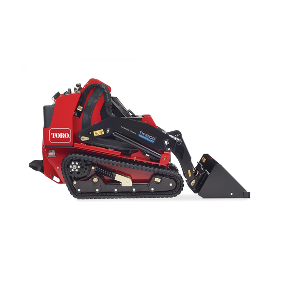
Toro TX 1000 Operator's Manual
Compact tool carrier, 4-in-1 electric/hydraulic bucket
Hide thumbs
Also See for TX 1000:
- Operator's manual (60 pages) ,
- Installation instructions manual (9 pages) ,
- Installation instructions (4 pages)

Subscribe to Our Youtube Channel
Related Manuals for Toro TX 1000


Summary of Contents for Toro TX 1000
- Page 1 Form No. 3418-252 Rev A 4-in-1 Electric/Hydraulic Bucket TX 1000 Compact Tool Carrier Model No. BU-003895 Model No. BU-003915 Model No. BU-004001 *3418-252* A Register at www.Toro.com. Original Instructions (EN)
-
Page 2: Table Of Contents
Whenever you need service, genuine Toro parts, or additional information, contact an Authorized Service Safety ............... 3 Dealer or Toro Customer Service and have the model General Safety ........... 3 and serial numbers of your product ready. Figure 1 Slope Safety ............ -
Page 3: Safety
Slope Safety Safety • Operate the machine up and down slopes with the heavy end of the machine uphill. Weight DANGER distribution changes with attachments. An empty bucket makes the rear of the machine the heavy There may be buried utility lines in the work end, and a full bucket makes the front of the area. -
Page 4: Attachment Safety
Attachment Safety Before Digging • Wear gloves, eye protection, long pants, To prevent damage and disruption to underground substantial slip-resistant footwear, and hearing pipe and cable networks in your proposed excavation protection during operation or while adjusting or site, contact the Dial Before You Dig service. You repairing the machine. -
Page 5: Safety And Instructional Decals
Safety and Instructional Decals Safety decals and instructions are easily visible to the operator and are located near any area of potential danger. Replace any decal that is damaged or missing. decal136-5844 136-5844 1. Press the joystick switch 3. Lock the accessory into left to open the bucket Forward. -
Page 6: Setup
Setup Loose Parts Use the chart below to verify that all parts have been shipped. Procedure Description Qty. – No parts required Prepare the machine. Connector mount bracket 7-pin connector Install the connector and connector Bolt (5/32 inches) mount bracket. Spacer Nut (5/32 inches) Relay and loader arm harness... -
Page 7: Install The Connector And Connector Mount Bracket
Park the machine on a level surface, engage the parking brake and lower the arms. Shut off the engine, remove the key and allow the engine to cool. Install the Connector and Turn the battery-disconnect switch to the off position; refer to your machine Operator’s Connector Mount Bracket Manual. -
Page 8: Connecting The Loader Arm Branch
Connecting the Loader Arm Branch Parts needed for this procedure: Relay and loader arm harness Plug nut Grommet Wire harness retainer Screw g242236 Figure 6 Procedure 1. Bulkhead coupler locknut 2. Connector mount bracket Loosen the captive screw (7/16 inch) on the bottom right of the rear-access cover and open Remove the plug and connect the hose fitting (Figure... - Page 9 g242240 Figure 9 1. Screw 3. Spacer tube g006230 2. Hose hold-down plate 4. Loader arm Figure 10 Relay and loader arm harness connections Find the loader end branch of the relay and 1. Relay branch 3. Power lead branch loader arm harness (Figure 10).
- Page 10 Route the loader end branch into the rear of the Route the loader end branch up into the outer machine along the lower front end of the loader protective sleeve, then route it along the bottom arm valve assembly (Figure 11) and out through of the inner hydraulic hose so that the wires the right hose access...
-
Page 11: Connecting The Relay And Power Lead Connectors
Tighten the terminal screws and pull on the wires to ensure that they are securely connected. Install the wire harness retainer and 2 screws (Figure 14). Connecting the Relay and Install the connector top half and screw on the plug nut securely, at the same time seating the Power Lead Connectors grommet (Figure... - Page 12 Connecting the Power Lead Install the 2 relays to the bucket relay connectors and continue to Connecting the Power Lead Branch Branch (page 12). With a cable tie, secure the harness to the hose fitting in the T1 port on the left side of the loader Assembling the Relay Connectors arm valve assembly.
-
Page 13: Removing The Existing Lever
Install the 5 A fuse into the inline fuse block on the power lead branch. Removing the Existing Lever No Parts Required Procedure g242427 Figure 22 Remove the retaining ring from the loader 1. Drill a 5 mm diameter hole 4. -
Page 14: Installing The 4-In-1 Bucket Lever
Attach the handle instructional decal onto the bottom left corner of the control panel decal as shown in Figure Note: Clean and prepare the control panel Installing the 4-in-1 Bucket decal before installing the handle decal. Lever No Parts Required Procedure Ensure that the rocker switches at the top of the 4-in-1 bucket lever are at right angles to the... -
Page 15: Installing The Valve Manifold Solenoid Harness
Installing the Valve Manifold Solenoid Harness No Parts Required Procedure Remove the 4 bolts and washers securing the manifold cover from the 4-in-1 bucket (Figure 25). g242609 Figure 26 1. Valve manifold 3. Valve manifold solenoid harness 2. Left and right solenoid connectors Tighten the centre screws on the solenoid connectors securely. -
Page 16: Testing The Installation
Lift up the spring-loaded cover on the 7-pin Turn the low flow switch on to activate the connector and insert the valve manifold solenoid auxiliary hydraulics low flow system. harness connector (Figure 26). Set the throttle to fast and lock the auxiliary hydraulics lever in the forward flow position;... -
Page 17: Completing The Installation
Product Overview Completing the Installation No Parts Required Procedure Tilt the 4-in-1 bucket back and lower the loader arm. Shut off the engine and remove the key. Check all hydraulic connections for leaks and correct as necessary. Check the hydraulic fluid level and correct as necessary;... -
Page 18: Specifications
Loader Arm/Attachment Tilt Lever Specifications Use the loader arm/attachment tilt lever to operate the Note: Specifications and design are subject to 4-in-1 bucket (Figure 30). change without notice. Important: For the bucket jaws to operate, you 4-in-1 Extra High Volume Bucket must have the auxiliary hydraulics lever in the forward detent position. -
Page 19: Maximum Material Density At Capacity
Maximum Material Density at Capacity The density of the materials moved by the bucket varies and, therefore, so does the amount of material that the bucket can carry before reaching the maximum load rating. The tables in Specifications (page 18) list the density of material that can be carried, both heaped and struck (i.e., leveled off), in the bucket. -
Page 20: Operation
Operation CAUTION Hydraulic couplers, hydraulic lines/valves, The 4-in-1 bucket can be used in 4 different operating and hydraulic fluid may be hot. If you contact modes: hot components, you may be burned. • Bucket • Wear gloves when operating the hydraulic •... -
Page 21: Bucket Operation
Bucket Operation You can draw the jaws together to use this attachment as a standard bucket. You can also open the 4-in-1 bucket jaws to dump the contents into a higher area than a standard bucket can reach. When loading material, always have the bucket level to the ground and move forward into the material to be lifted. -
Page 22: Maintenance
Maintenance Recommended Maintenance Schedule(s) Maintenance Service Maintenance Procedure Interval • Lubricate the bucket • Ensure that all fasteners are securely tightened. • Inspect the hydraulic system for leaks and loose fittings. • Clean the areas around the bucket cylinder and mount plate pivot. Before each use or daily •... -
Page 23: Storage
Storage Before long-term storage, wash the attachment with mild detergent and water to remove dirt and grime. Check and tighten all bolts, nuts and screws. Repair or replace any part that is damaged or worn. Ensure that all the hydraulic hose couplers are connected together to prevent contamination entering the hydraulic system. -
Page 24: Troubleshooting
Troubleshooting Problem Possible Cause Corrective Action Bucket does not open or close. 1. Electrical circuit issue. 1. Inspect the wire harness and electrical connections. Refer to the wiring diagram. 2. The fuse(s) are blown. 2. Replace any blown fuses. 3. There are loose power or earth 3. -
Page 25: Schematics
Schematics g239505 (Rev. A) - Page 26 Notes:...
- Page 27 Notes:...
- Page 28 All repairs covered by these warranties must be performed by an Authorized Toro Service Dealer using Toro approved replacement parts. Repair by an Authorized Toro Service Dealer is your sole remedy under this warranty.
Need help?
Do you have a question about the TX 1000 and is the answer not in the manual?
Questions and answers