AMX Enova DVX-2150HD Installation Manual
6x3 all-in-one presentation switcher
Hide thumbs
Also See for Enova DVX-2150HD:
- Operation/reference manual (139 pages) ,
- Quick start manual (3 pages)
Advertisement
Quick Links
Overview
Note: For more information, consult the Enova DVX-2150HD/2155HD 6x3 All-In-One
Presentation Switcher Operation/Reference Guide available at www.amx.com.
The DVX-2150HD-SP (FG1905-11), DVX-2150HD-T (FG1905-13), DVX-2155HD-SP
(FG1905-12), and DVX-2155HD-T (FG1905-14) are six input, three output, multi-format
matrix switchers with built-in video scalers, microphone mixer, amplifier, and device
controller. These presentation-style switchers incorporate the following:
•
A NetLinx controller (equivalent of a NetLinx 3101-SIG central controller)
•
Integrated Multi-format and UTP audio / video switcher
•
Video scaler
•
Audio processor with mic mixing
•
Volume controller and audio amplifier
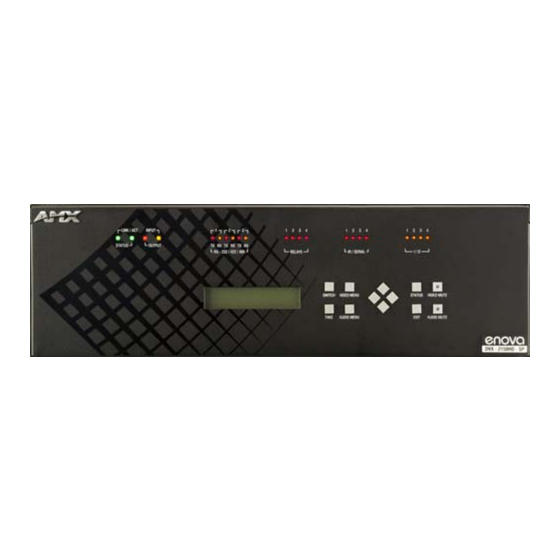
FIG. 1
Enova DVX-2150HD-SP 6x3 All-In-One Presentation Switcher (front panel)
The following table lists the specifications for the Enova DVX-2150HD/2155HD 6x3
All-In-One Presentation Switcher:
Enova DVX-2150HD/2155HD Specifications
Power:
100-240V, 47/63 Hz AC supply
Power
• 80 Watts typical without amplifier
Consumption:
• 85 to 90 Watts typical average with amplifier
• 30 Watts typical in low-power mode
Memory:
• 256 MB SDRAM
• 256 MB Flash
Amplifier:
• 2 x 25W into 8 Ohms Class D stereo amplifier (capable of driving
loads in the range of 2-8 ohms) (-SP models only)
• 70V or 100V at 75W amplified variable mono audio (-T models only)
Enclosure:
Metal with black matte finish
Integrated
Equivalent of a NetLinx 3101-SIG central controller on-board.
Controller:
Front Panel Components:
LEDs:
• LINK/ACT (green) - blinks when receiving Ethernet data packets.
• STATUS (green) - blinks when the system is communicating
properly.
• INPUT (yellow) - blinks when the Controller is receiving data.
• OUTPUT (red) - blinks when the Controller is transmitting data.
• RS-232/422/485 (red/yellow) - indicate ports are transmitting or
receiving data.
• RELAYS (red) - indicate whether relay channels are active (closed).
• IR/SERIAL (red) - indicate whether IR/Serial channels are
transmitting control data.
• I/O (yellow) - indicate whether I/O channels are active.
LCD display:
Displays volume level and Video, Audio, and Status menu options.
Front panel
• Switch
pushbuttons:
• Video Menu
• Status
• Video Mute
• Navigational buttons
Rear Panel Components:
RS-232/422/485
3 DB9 (male) connectors for serial control
RELAYS:
1 8-pin 3.5 mm captive-wire connector for Relay control
IR/SERIAL:
8 2-pin 3.5 mm captive-wire connectors for IR/Serial control
I/O:
1 4-channel binary I/O port for contact closure and voltage sensing.
AUDIO INPUTS: 4 analog audio inputs:
• 2 female 1/8" stereo mini-phono jacks for unbalanced audio
• 2 3.5mm 5-pin captive-wire connector for line level audio
MIC INPUTS:
2 3.5mm 3-pin captive-wire connectors for up to 2 mono microphones
AMP OUT:
• 1 5mm 4-pin captive wire connector (-SP models only).
• Two 2-position captive wire connectors for 70V or 100V mono
amplified audio output (-T models only).
AUDIO
2 3.5mm 5-pin captive-wire connectors for line level audio
OUTPUTS:
Enova DVX-2150HD/2155HD 6x3 All-In-One Presentation Switcher
• 1 MB Non-volatile (NVRAM)
• Take
• Audio Menu
• Exit
• Audio Mute
Enova DVX-2150HD/2155HD Specifications (Cont.)
S/PDIF
1 Coaxial RCA connector for digital S/PDIF audio output
OUTPUT:
MULTI-FORMAT
2 DVI-I input connectors
VIDEO INPUTS:
HDMI INPUTS:
• 4 HDMI inputs (3-6) (DVX-2150HD devices only)
• 2 HDMI inputs (3-4) (DVX-2155HD devices only)
DXLINK
2 RJ-45 inputs (5-6) for video, audio, Ethernet, and bi-directional
INPUTS:
control of DXLink devices (DVX-2155HD devices only)
VIDEO
• 2 HDMI Output connectors (1-2)
OUTPUTS:
• 1 DXLink Cat5 output (3)
CONFIG DIP
8-position Master configuration DIP switch
Switch:
PROGRAM
DB9 connector (male) for serial communication.
Port:
ID Pushbutton:
Black ID pushbutton sets the NetLinx Device ID assignments of the
Internal Control Device.
LAN 10/100
RJ-45 connector provides TCP/IP communication.
Port:
AxLink Port:
1 3.5 mm 4-pin captive-wire connector provides data and power to
external control devices.
Power
IEC Power cord connector: 100-240V AC, 50-60Hz, 3.3A
Connector:
Operating
Storage temperature: -10º C to 70º C (14º F to 158º F)
Environment:
Operating Temperature: 0º C to 40º C (32º F to 104º F)
Operating Relative Humidity: 5% to 85% non-condensing
Weight:
18.2 lb (8.26 kg)
Dimensions
5 3/16" x 17" x 14" (13.2 cm x 43.2 cm x 35.6 cm)
(HWD):
Certifications:
• FCC Part 15 Class A
• IC CISPR 22 Class A
• LVD EN 60950-1
• cULus UL 60950-1
Included
• 1 Power Cord, Universal (64-0009)
Accessories:
• 2 Connector, Phoenix2, M, TH, R/A, BLACK, 5.08mm (41-0158-SA)
• 4 Connector, Phoenix5, F, BLACK (41-0336)
• 2 Connector, Phoenix3, F, BLACK (41-0338)
• 1 Connector, Phoenix4, F, TH, BLACK, 3.5mm (41-5047)
• 2 Connector, Phoenix, 8-pin, FEM, BLACK (41-5083)
• 1 Connector, Phoenix, 6-pin, FEM, BLACK (41-5063)
• 2 Front Rack Mounting Brackets (62-1905-16 and 62-1905-17)
• 2 CC-NIRC, IR Emitter with 3.5mm Phoenix Connector
(FG10-000-11)
• 1 CC-DVIM-VGAF, DVI to HD-15 Female Adapter (FG10-2170-13)
• 1 Commoning Strip, Cypher, 8 Pos., 3.5 mm, Phoenix Connector
(41-2105-01)
Optional
• CC-DVI-5BNCM DVI to 5 BNC adapter cable (FG10-2170-08)
Accessories
• CC-DVI-RCA3M DVI to 3 Male RCA adapter cable (FG10-2170-09)
• CC-DVI-SVID DVI to S-Video adapter cable (FG10-2170-10)
• CC-DVIM-VGAF DVI to HD15 female adapter (FG10-2170-13)
• CC-3.5ST5-RCA2F 5-Pin Phoenix Cable to 2 RCA Female
(FG10-003-20)
• AVB-RX-DXLINK-HDMI DXLink™ HDMI Receiver Module
(FG1010-500)
• AVB-TX-HDMI-DXLINK DXLink HDMI Transmitter Module
(FG1010-300)
• AVB-TX-MULTI-DXLINK DXLink Multi-Format Transmitters
(FG1010-310)
• AVB-WP-TX-MULTI-DXLINK DXLink Multi-Format Wallplate
Transmitters (FG1010-320-BL/WH)
Mounting the DVX into an Equipment Rack
The DVX occupies three rack units in a standard equipment rack. Install the included
rack mounting brackets using the supplied mounting screws prior to securing the unit in
the rack.
Warning: The DVX should not be installed in enclosed spaces. ALWAYS ensure that
the rack enclosure is adequately ventilated. Do not block any ventilation openings. It is
recommended that you leave 1 RU of space above the DVX when you install it in a rack.
DO NOT stand other units directly on top of the DVX when it is rack mounted, as this
will place excessive strain on the mounting brackets.
ALWAYS ensure that the rack enclosure is adequately ventilated. Do not block any
ventilation openings. Sufficient airflow must be achieved (by convection or forced-air
cooling) to satisfy the ventilation requirements of all the items of equipment installed
within the rack.
Installation Guide
• C-Tick CISPR 22 Class A
• IEC 60950-1
• CE EN 55022 Class A and EN 55024
Advertisement

Related Manuals for AMX Enova DVX-2150HD


Summary of Contents for AMX Enova DVX-2150HD
- Page 1 FIG. 1 Enova DVX-2150HD-SP 6x3 All-In-One Presentation Switcher (front panel) AxLink Port: 1 3.5 mm 4-pin captive-wire connector provides data and power to The following table lists the specifications for the Enova DVX-2150HD/2155HD 6x3 external control devices. All-In-One Presentation Switcher: Power IEC Power cord connector: 100-240V AC, 50-60Hz, 3.3A...
- Page 2 ©2012 AMX. All rights reserved. AMX and the AMX logo are registered trademarks of AMX. AMX reserves the right to alter specifications without notice at any time. 3000 RESEARCH DRIVE, RICHARDSON, TX 75082 • 800.222.0193 • fax 469.624.7153 • technical support 800.932.6993 • www.amx.com...
Need help?
Do you have a question about the Enova DVX-2150HD and is the answer not in the manual?
Questions and answers