
Subscribe to Our Youtube Channel
Related Manuals for Sanken SVCO6


Summary of Contents for Sanken SVCO6
- Page 1 High Performance Vector Control Inverter Instruction Manual SANKEN ELECTRIC CO., LTD.
- Page 3 Thank you for purchasing the Sanken High Performance Vector Control Inverter SVC06 series. This inverter is designed to drive an induction motor at a variable speed. The inverter has a built-in microprocessor providing a wide range of functions and easy operability. To ensure many years of trouble-free operation and maintain optimum performance, be sure to read through this manual before using the product.
-
Page 4: Table Of Contents
CONTENTS Safety Notes ............................- 5 - Important Notes ........................- 5 - Notes on Use .......................... - 5 - Notes on Installation ....................... - 6 - Notes on Handling and Moving ....................- 6 - Notes on Wiring ........................- 7 - Notes on Operation ......................... -
Page 5: Table Of Contents
Terminal Functions and Wiring ..................- 257 - 7-4-3 Inverter Operation and Related Function Code Setting by Serial Communication ..- 258 - 7-4-4 Communication with Dedicated Protocol (SANKEN Communication Protocol)..- 260 - 7-4-5 Programming Design....................- 262 - - 3 -... -
Page 6: Table Of Contents
7-4-6 Modbus-RTU Communication ..................- 279 - Protection & Error Function ........................ - 290 - Operation Error ........................- 290 - 8-1-1 List of Error Operation ....................- 291 - Conflict & Interference Error ....................- 292 - 8-2-1 List of Conflict & Interference Error ................- 292 - Warning Status ........................ -
Page 7: Important Notes
1. Safety Notes Important Notes Danger Caution: risk of electric shock It is absolutely prohibited to remove the cover The risk of casualties exists because there are high-voltage circuits inside, accidental touch of which would cause electric shock. Caution: Fire Hazard!... -
Page 8: Notes On Installation
1–3 Notes on Installation Notes on Installation Caution It is absolutely prohibited to store or use the inverter under the environmental conditions described below. Failure to observe this warning may result in a fault, damage, or deterioration, which could lead to fire. ... -
Page 9: Notes On Wiring
1–5 Notes on Wiring Notes on Wiring Danger Wiring must be performed by qualified personnel. Failure to observe this warning may result in an electric shock or fire due to incorrect wiring. Do not connect AC power to an output terminal (U, V, or W). Failure to observe this warning may result in personal injury or fire. -
Page 10: Notes On Operation
1–6 Notes on Operation Notes on Operation Danger Attach the front cover before turning the power on. And, do not remove the front cover when the power is on. Failure to observe this warning may result in electric shock. ... -
Page 11: Notes On Maintenance And Inspection
1–7 Notes on Maintenance and Inspection Notes on Maintenance and Inspection Caution Works such as maintenance, inspection and replacement of parts etc. can only be carried out by professional electricians. [Take off any metal item (such as watch, bracelet, etc.) before working on the equipment.] [Use insulated tools.] Failure to observe this warning may result in electric shock or burns. -
Page 12: Checking The Product
2. Checking the Product and Precautions on Use Checking the Product After unpacking the product, check the following: Check that the product has not been damaged during delivery, such as depression of casing etc.. If such problems are found, please contact the retailer. Danger ... -
Page 13: Precautions On Use
Precautions on Use Precautions on Use Use the product in a location satisfying the standard environmental specifications (temperature, humidity, vibration, dust, water drop, and toxic gases etc.). Before starting up the product for the first time, carefully check the wiring. Make sure that the power cable (input) and motor cable (output) are connected correctly. -
Page 14: Names Of Parts
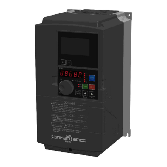
Names of Parts Names of Parts [Top View] ① ② [Bottom View] Figure 2-2 Names of Parts Table 2-1 Names of Parts Name Function LCD display part Refer to [Chapter 5 Operation Panel] Operation Panel Refer to [Chapter 5 Operation Panel] Wiring Hole Refer to [Chapter 4 Wiring] Air Inlet... -
Page 15: Installation Location And Storage
3. Installation Installation Location and Storage This equipment is an electronic control device. Please pay full attention to environment of the device before it is used. Caution Mount the inverter on a metal surface or other non-flammable surface. Failure to observe this warning may result in a fire. ... - Page 16 Installation Location and Storage Table 3-2 (2) Capacity Modes Capacity Mode A Mode B 0900 90kW (150%) 110kW (120%) 1100 110kW (150%) 132kW (120%) 1320 132kW (150%) 160kW (120%) 1600 160kW (150%) 200kW (120%) 1850 185kW (150%) 220kW (120%) 2000 200kW (150%) 250kW (120%) 2200...
- Page 17 Installation Location and Storage Capacity Screws Recommended Screw Tightening Torque 4.3N•m -4 SVC06-0370 (2.3-5.6N•m) -4 SVC06-0450 10.8N•m -4 SVC06-0550 -4 (5.4-13.8N•m) SVC06-0750 -4 SVC06-0900 -4 SVC06-1100 -4 SVC06-1320 42N•m -4 SVC06-1600 -4 (35-50N•m) SVC06-1850 -4 SVC06-2000 -4 SVC06-2200 -4 SVC06-2500 - 15 -...
-
Page 18: Installation Direction And Space
Installation Direction and Space Installation Direction and Space (1) This inverter is of the wall mounting type. (2) Install the inverter vertically on a flat mounting surface. (3) Since the inverter generates heat, provide adequate space around it to ensure good heat dissipation conditions. -
Page 19: Removal And Installation Of The Front Cover
Removal and Installation of the Front Cover Removal and Installation of the Front Cover 3-3-1 Small-Capacity Model (SVC06-0015~0075-**2/SVC06-0007~0150-**4) (1) Removal of front cover (lower) Unscrew the M4 screws, and pull the cover toward you while pressing the Dent portion on both sides of the front cover (lower). -
Page 20: Middle-Capacity Model (Svc06-0185~0750-**4)
Removal and Installation of the Front Cover (3) Installation When installing, work in reverse order. 3-3-2 Middle-Capacity Model (SVC06-0185~0750-**4) (1) Removal of front cover (lower) and internal sealing plate (iron) Unscrew the M4 screw on the front cover (lower) and pull down gently, and then the front cover (lower) will be removed. -
Page 21: Large-Capacity Model (Svc06-0900~2500-**4)
Removal and Installation of the Front Cover 3-3-3 Large-Capacity Model (SVC06-0900~2500-**4) (1) Removal of front cover (lower) Unscrew the M4 screw, gently lift up and take off the cover. Please carry out this work during the main circuit wiring, control circuit wiring, and SW1 switching. Terminal block for control circuit... -
Page 22: Removal And Installation Of The Operation Panel
3-4 Removal and Installation of the Operation Panel Removal and Installation of the Operation Panel 3-4-1 Removal of Operation Panel Hook ① and ② on the cover with your fingers, and take off the panel, pull it toward you while pressing the jack catch on ②... -
Page 23: Connection With Peripheral Devices
4. Wiring Read the Notes on Wiring (1-5) before wiring. Failure to observe this warning may result in personal injury or fire. Connection with Peripheral Devices Name Purposes and Detailed Description Power supply When there is need for matching the system power Input power supply supply voltage with rated inverter input voltage, please transformer... -
Page 24: About Wiring
About Wiring About Wiring Before carrying out wiring work, turn the inverter‘s input power supply to ―OFF‖ (disconnected) first, and then check with a circuit tester that no applied voltage is present. Check also that the CHARGE lamp is not lit. - Page 25 About Wiring ● Do not share the grounding wire with the welding machine or the power equipment. ● Use the grounding wire prescribed in the technical standards for electrical equipment, and shorten wiring length as much as possible. ● Be careful not to loop the grounding wire when using multiple inverters. (a) Correct (b) Correct (c) Incorrect...
-
Page 26: Terminal Connection Diagram
Terminal Connection Diagram Terminal Connection Diagram Brake unit Note 7 (optional) DC reactor Brake resistor oputional (Option) oputional (Option) motor MCCB Main circuit Note 1 Single-phase 220V Grounding Groundig Grounding Note 1 ~ In operation 1 Multifunctional contact output Factory Preset: abnomal alarm signal Frequency matching... - Page 27 Terminal Connection Diagram Please use shielded wires for analog input and output wires, contact input wire (digital multi-function input terminals). (The set values of functional terminals are factory preset values.) In order to prevent noise malfunction, please separate wiring as much as possible power line and signal line. (10cm or more) ...
-
Page 28: Composition Of Main Circuit Terminals
Composition of Main Circuit Terminals Composition of Main Circuit Terminals 4-4-1 Description of Main Circuit Terminals Terminal Name Description Symbol R,S,T Input power Terminals connected to a three-phase commercial power supply supply terminals U,V,W Inverter output terminals Terminals connected to a three-phase induction motor P,P1 DC reactor connection Terminals connected to a DC reactor *1... -
Page 29: External Brake Resistor Selection Example
Composition of Main Circuit Terminals (4) SVC06-0900~1100-**4 (5)SVC06-1320~1850-**4 DC Reactor DC Reactor Motor Motor (6)SVC06-2000~2500-**4 DC Reactor Motor 4-4-3 External Brake Resistor Selection Example 200V class External brake resistor (recommended) External brake resistor (limit value) Model Resistance Capacity *1 Resistance Capacity *1 60Ω... - Page 30 Composition of Main Circuit Terminals 400V class External brake resistor (recommended) External brake resistor (limit value) Model Resistance Capacity *1 Resistance Capacity *1 700Ω or more 380Ω or more 100W 150W SVC06-0007-4 320Ω or more 190Ω or more 200W 300W SVC06-0015-4 160Ω...
-
Page 31: Capacities Of Mccb And Mc And Wire Size
Composition of Main Circuit Terminals 4-4-4 Capacities of MCCB and MC and Wire Size 200V class Control Main circuit Electromagnetic circuit contactor) Recommended wire size [mm MCCB Max. Model Tighte Max. Rated Rated wire -ning wire making current size current size torque P and P1... - Page 32 Composition of Main Circuit Terminals Control (Electromagnetic Main circuit circuit contactor) Recommended wire size [mm Max. wire MCCB Max. Model Tighte Rated size Rated wire -ning making current size P and P1 Output current torque Input wire wires wire [N•m] 250×2(200) SVC06-2200-4 150×2(200)
-
Page 33: Molded Case Circuit Breaker (Mccb) Selection Example
Composition of Main Circuit Terminals 4-4-5 Molded Case Circuit Breaker (MCCB) Selection Example 200V class Without DC reactor With DC reactor Motor Molded Case Earth Leakage Molded Case Earth Leakage Model Power Circuit Breaker Circuit Breaker Circuit Breaker Circuit Breaker (MCCB) (ELB) (MCCB) -
Page 34: Composition Of Control Circuit Terminals
4-5 Composition of Control Circuit Terminals Composition of Control Circuit Terminals 4-5-1 Wire Size and Terminal Arrangement Terminal screw diameter: M3 Recommended wire size 0.75 [mm Tightening torque: 0.5[N•m] The arrangement of control circuit terminals is as shown in the following. +24V1 DCM2 +24V2 ACM2 VIF1... -
Page 35: Functions Of Control Circuit Terminals
Composition of Control Circuit Terminals 4-5-2 Functions of Control Circuit Terminals Table 4-3 Description of Control Circuit Terminals Terminal Type Terminal Name Function Description Rated Specification Notes Symbol Common terminals for digital input and Total DCM1 Digital signal output signals and for +24V1 and current consumed: DCM2 common terminals... - Page 36 4-5 Composition of Control Circuit Terminals Terminal Type Terminal Name Function Description Rated Specification Notes Symbol (1) By selecting a function code VIF1 Analog input VIF2 terminals corresponding to each function, VIF3 current / voltage of the 3 channels can be switched separately. (2) When the frequency setting is For voltage input: selected, the current / voltage input...
- Page 37 Composition of Control Circuit Terminals Terminal Terminal Type Function Description Rated Specification Notes Symbol Name (1) The Current output Current output range: (1) Adjust F1515 so that the current ACM1 terminals 4-20mA current output under proportional Load resistance: maximum output frequency output frequency of 500Ω...
-
Page 38: Multifunctional Input / Output
4-5 Composition of Control Circuit Terminals 4-5-3 Multifunctional Input / Output The so-called multifunctional input / output means freely assigning various functions to multifunctional input / output terminals through the data selection of function codes. The multifunctional input / output is divided into the input terminal of contact input and output terminal of open collector. -
Page 39: Control Logic Switching
Composition of Control Circuit Terminals 4-5-4 Control Logic Switching Through the switching of switches on the main control board, multifunctional input terminals DI1 - DI8 can be switched between SINK and SOURCE. When switching, use switch SW1 on the main control board. ... -
Page 40: Connection Of Control Circuit Terminals
Composition of Control Circuit Terminals ● When the transistor is used for external control signals, please set and wire transistors of different types as shown in the following table. Transistor Using internal power supply of the inverter Using external 24V power supply (*) NPN Type Set SW1 as SINK Unable to connect... - Page 41 Composition of Control Circuit Terminals 1) Potentiometer for frequency setting Please install a 5kΩpotentiometer of 0.3w or above, set the 1st speed frequency and select the frequency settings of current and voltage by selecting function code F1002. Please use shielded wires for wiring, please connect one end of the control terminal shield to the shield terminal ASG, while leave the other end open.
- Page 42 Composition of Control Circuit Terminals 3) Signal mode switching for emergency stop (multifunctional input ES terminal) The figure below shows an example of signal switching when the multifunctional input terminal is set for the external emergency stop (ES) command. ...
-
Page 43: Communication Function Terminal
Composition of Control Circuit Terminals 4-5-6 Communication Function Terminal RS485terminal block SOURCE RS485 communication The communication control with peripheral devices can be realized by using RS485 communication terminal block on the following main control board. SW2 is a switch for turning ON / OFF the terminating resistor. Please set only the farthest terminating resistor switch of the inverter to ON. -
Page 44: Connection Of Pg Sensor
Composition of Control Circuit Terminals 4-5-7 Connection of PG Sensor 1) Connection example when the control terminal of main control board is used (open-collector mode) The power supply of PG sensor can be supplied by inverter Inverter Phase A pulse Phase B pulse Set function code F8109 (PG:PG output formation selection) to 1. -
Page 45: Installation And Wiring Of Optional Board
Installation and Wiring of Optional Board Installation and Wiring of Optional Board 4-6-1 Overview of Optional Board 2 optional boards can be installed on one inverter at the same time. 2 slots are provided in the inverter, but the shape of optional board may vary between different optional boards. -
Page 46: About Emc Filter
About EMC Filter About EMC Filter This inverter can be provided with built-in EMC filter (order requirement). Although the EMC filter can effectively reduce the interference transfer, it will increase the leakage current. ON or OFF of the EMC filter can be selected as follows through the on / off of the connector. Press the jack catch, release lock state And then the connector can be pulled freely... -
Page 47: Names And Functions Of Parts Of The Operation Panel
5. Operation Panel Names and Functions of Parts of the Operation Panel Display part (LCD) LCD panel part F1 key・ F2 key LED panel part LED Panel parts Monitor mode display Monitor authorization display 7-segment monitor Control authorization toggle key Operating mode display Drive key Stop key... -
Page 48: Lcd Display Part
Names and Functions of Parts of the Operation Panel 5-1-1 LCD Display Part The LCD display is a part of the LCD monitor. In conjunction with 7-segment monitor, the operation status and the function code settings etc. can be indicated. 5-1-2 LCD Operation Part Key Name... -
Page 49: Switching Of Statuses
Switching of Statuses Switching of Statuses The operation panel has two display modes: [Status display mode] and [function code display mode], and the modes can be toggled by pressing the key Table 5-1 7-segment monitor display modes Display Mode Display Contents •... -
Page 50: Status Display Mode
Status Display Mode Status Display Mode In status display mode, inverter status monitoring, alarm display, setting of each commands (frequency, speed, torque) and operations such as running and stop of inverter can be implemented. 5-3-1 Version Display Shortly after the power-on of the equipment, the software version of inverter will be displayed on 7-segment monitor. The following is: display example for software version: VER 1.00. - Page 51 Status Display Mode Monitor mode display refers to the contents displayed on the 7-segment monitor Table 5-3 Display contents of monitor mode Display Contents Unit Display Contents Display of 7-segment Monitor Hz A rpm % M Frequency Running: the lit lamp indicates output frequency Stopped: the flashing lamp indicates set frequency...
-
Page 52: Alarm Display
Status Display Mode During selection of an operation command from an external terminal or from communication through the function code, as the key is pressed and held for about 2 seconds, running operation can be carried out instantly by the operation panel. -
Page 53: Command Setting
Status Display Mode 5-3-4 Command Setting The command setting of the inverter frequency, speed and torque can be input by using the quick knob. Command setting is possible by function code (F1201 and F1202) combination. Each command setting is difference by 7-segment monitor state following bellow the table. - Page 54 Status Display Mode (2) Command setting B Command setting B is a method for changing command by dialing the quick knob each time. This is an effective method for fine-tuning of the set command during observation of the load conditions. ...
-
Page 55: Function Code Display Mode
Function Code Display Mode Function Code Display Mode Function code display mode can be used to set various functions of inverter. 5-4-1 Status Transition Diagram 7-segment monitor Function block Function code Setting input display selection selection Status F10__ F1001 display OK:... -
Page 56: Basic Operation
Function Code Display Mode 5-4-2 Basic Operation The basic operation is used for changing the value of a function code. Operation example: setting F1414=10 Operation Display Description Display of status monitor (frequency display) Pressing the key shows the function block selection Turn the quick knob, then the function block number will change accordingly. -
Page 57: Confirming Operation
Function Code Display Mode 5-4-3 Confirming Operation For some function codes, operation needs to be re-confirmed to prevent data rewriting due to misoperation. Operation example: setting F1001=10 Operation Display Description Display of status monitor (frequency display) Press the key, the screen will display function block selection By turning the quick knob, you can select the target function module. -
Page 58: Signed Operation
Function Code Display Mode 5-4-4 Signed Operation For some function codes, they can be set with values containing signs (polarity). Operation example: setting F1503=-5.0 Operation Display Description Display of status monitor (frequency display) Press key, then the screen will display function block selection interface Turn the quick knob to select the target function module. -
Page 59: Special Functions
Special Functions Special Functions 5-5-1 Copy Function Operation The so-called copy function is the function which transfers the function code data to other inverters after transferring the function code data from one inverter side to the operation panel. The copy function is an effective function where several inverters need to be set with the same function code data. Only 1 inverter is set, while other inverters can also receive the same function code data, thus the same function code setting can be easily implemented. -
Page 60: Changed Code Display Operation
Special Functions 5-5-2 Changed Code Display Operation Considering current function code data may be different from the factory presets of product or the user's initial value, the function for displaying a changed function code and its data. This is an effective function for inquiring the difference between current function code and product‘s factory preset or the user initial value. -
Page 61: Function Code Initialization Operation
Special Functions 5-5-3 Function Code Initialization Operation The inverter‘s function code settings can be returned to factory presets through this function. Inverter‘s initial value can be set to the factory preset or the data determined by the user (i.e. user‘s initial value). Also, the initial value can be selected between the factory presets and the user‘s initial value. -
Page 62: Alarm Contents Reading Operation
Special Functions 5-5-4 Alarm Contents Reading Operation Alarm history record display is a function for displaying alarms occurred in the past. The latest 5 alarms will be recorded. If a new alarm occurs, then the first alarm will be deleted. Operation example: reading alarm contents Operation Display... -
Page 63: Alarm Status Confirmation Operation
Special Functions 5-5-5 Alarm Status Confirmation Operation Alarm status confirmation is a function for displaying the inverter‘s status when an alarm occurs. It can be used to confirm the latest 5 alarm statuses through function codes F1806 - F1810. If a new alarm occurs, then the first alarm will be deleted. -
Page 64: Serial Number Display
Special Functions 5-5-6 Serial Number Display A serial number display is a function which displays the serial number of the main part of an inverter on 7 segment monitor of an operation panel. The example of operation : When the serial number of an inverter is checked Operation Display Description... -
Page 65: Segment Monitor Display List
Special Functions 5-5-7 7-Segment Monitor Display List Monitor display Description During initialization, the data is displayed flashing. During initialization of user data, the data is displayed flashing. During confirmation of user data, the data is displayed flashing. The detonation indicates the need for reconfirmation operation using function code It is displayed flashing during search of the function code, of which the user data is discrepant from default settings. -
Page 66: Connecting Operation Panel With Extension Cable
Connecting Operation Panel with Extension Cable Connecting Operation Panel with Extension Cable If the operation panel is connected to inverter with the extension cable, then the operation panel can be installed in other instrument frame. (See Chapter 12: outside view of 12-2 Operation Panel for installation opening drawing). The extension cable length shall not be more than 5m. -
Page 67: Operation
6. Operation Wiring shall not be made after connecting to power supply. Failure to observe this warning may result in personal injury, fire or electric shock. Before undertaking the work, safety notes must be checked. Failure to observe this warning may result in personal injury or fire. ... -
Page 68: Operation Steps
6–1 Operation Steps Operation Steps The following flowchart shows all the operation steps before and after operation of the inverter. Please follow the following flow chart to carry out test run. Prepration starts Set up installation wiring 6-2-1 Confirmation Before inspection before power input Power Input... -
Page 69: Test Run
Test Run Test Run 6-2-1 Confirmation Before Power Input ● Please check the following items after installation wiring and other works and before power-on. Table 6-1 Confirmation items before power input Item Content If the power supply voltage coincides with the inverter‘s capacity and voltage. Power supply voltage confirmation Main wiring confirmation ... -
Page 70: Basic Setting (1)
Test Run 6-2-3 Basic Setting (1) Carry out setting after the basic operation settings have been confirmed. The selection of rated values can be made by switching through the following function code. Table 6-3 Basic function (1) Function Name Overload Maximum Remarks code... -
Page 71: Basic Setting (2)
Test Run (5) Auto torque boost control The inverter is provided with voltage compensation function and slip compensation function. The former is used for auto-regulating the inverter output voltage, while the latter is used for slip frequency compensation based on the load. Use F2007 to select the above functions. - Page 72 Test Run Table 6-7 Auto tuning mode Function Code F1001 Function Motor Parameters Remarks Auto tuning mode 1: Measure Primary resistance R1 For cases where the motor when the motor shaft is fixed Secondary resistance R2 can not operate Primary inductance L1 Secondary inductance L2 Mutual inductance Lm Auto tuning mode 2: Measure...
- Page 73 Test Run [Motor parameter auto tuning steps] (1) Setting of motor ratings Set all the motor ratings into function codes F5001-F5005 correctly. ・Please make function code display by pressing the key. ・After displaying the F5001 in the quick knob, please press the key.
- Page 74 Test Run ② Setting of F5002 F5005 Set rated current, frequency, speed and insulation type of the connected motor. Under normal circumstances, please set according to the motor ratings. If the value set is incorrect, the motor parameters auto tuning results and the control characteristics of torque control will become adverse. Note 1): The settings are interdependent with the settings of motor poles, voltage and capacity (F5001).
- Page 75 Test Run [Note: Notes on carrying out motor parameter auto tuning mode] ① Before carrying out auto tuning mode 2, be sure to disengage the load shaft of motor. If the load is not disengaged (for example, one-piece brake motor), then the auto tuning mode 2 can not carry out correct auto tuning.
-
Page 76: Basic Setting (3)
Test Run 6-2-7 Basic Setting (3) Please set the function codes used for setting the operation command and frequency command. Table 6-9 Basic function (2) Function code Name Content Remarks F1002 1st speed 1: Operation panel Please set the frequency 2: External analog VIF1 voltage (0-5V) setting to values setting... -
Page 77: Operation Confirmation
Test Run Operation command values can be changed using the status of multifunctional input terminals. According to the status of multifunctional input ROPE or RCOM, the operation commands as shown in the table below can be selected. See F1101 in Chapter 7-3 for details. ROPE RCOM Operation Command... - Page 78 Test Run (2) Confirmation items during test run Please confirm the contents listed in the table below Table 6-11 Confirmation items during test run Item Result Motor rotation direction Is it the specified rotation direction? Motor operation 1 Are the acceleration and deceleration smooth? Motor operation 2 Is there any abnormal sound or vibration? Inverter fan operation...
- Page 79 Test Run (3) Operation preparation After confirmation of test run and normal operation confirmation of motor, please implement the connection with the mechanical system. 1 Please set the function codes related to machine action. 2 Check the interface matched with peripheral mechanical equipment. (4) Operation confirmation Before delivery, various functions of the inverter have been set up as shown in the function code list.
- Page 80 Test Run Note 1: If both input signals FR (Forward) and RR (Reverse) are input at the same time, then the inverter will not operate. And if both signals are simultaneously input during operation, then [Output Frequency Lock] will act. If this is done during accelerating or decelerating, the change of output frequency will also be locked and RREV (Reverse revolution function will be disable.
- Page 81 Special Functions Special Functions 6-3-1 JOG Operation (1) Short-circuiting the multifunctional terminal JOG with DCM1, 2 forms a JOG operation mode. (2) For JOG operation, please set the F1101 = 2, and then short-circuit the multifunctional terminal FR or RR with DCM1, 2 after short-circuiting the multifunctional terminal JOG with DCM1, 2.
-
Page 82: Notes On Free Run Stop Terminal (Mbs)
Special Functions (2) When the external signal terminals are used to operate and stop the inverter, and you do not want the motor to automatically restart after recovery from a power failure, use the above circuit and set F1108=0. (3) When operating with the hold function, the inverter does not restart after recovery from the following conditions. - Page 83 Special Functions 6-3-4 3 Wired Operation Set F1101=4 and wire the circuit as shown in Figure 6-6, the inverter can operate run and stop by using a push button. OFF:FR ON:RR STOP Figure 6-6 Cricuit of 3wired operation If STOP is ON and RUN is ON, then the inverter will start driving. If STOP is OFF, then the inverter will stop driving. This operation is not same hold operation.
- Page 84 Special Functions Note 1:FR(Forward), RR(Reverse) and FR/RR(Revolution direction) are different signals each other. Note 2:If FR/RR state is changed at inverter driving, then revolution direction of motor can change. Revolution direction decide by F1001(Motor control mode selection) setting value. • F1001 = 1 (V/f control mode) and F1309 = 0 The inverter operates according to the function code settings when starting and stopping.
-
Page 85: Definition Of Technical Terms
Definition of Technical Terms Definition of Technical Terms Output frequency Operation signal DC braking signal Main switching device drive signal Multifunctional output terminal operation 1 Multifunctional output terminal operation DC braking DC braking Standby Stopped Running Stopped Figure 6-7 Operation action Table 6-12 Explanation of Terms Term Definition... -
Page 86: Representation And Description Of Function Codes
7. Function Code Representation and Description of Function Codes By changing the function code, the inverter action can be changed. Function codes are functionally classified into "function blocks". To change the function code, first select the function block, and then select the serial number of the function code to be changed. A function code can be set through operation panel (see sections 5-4 and 5-5), or communication (see section 7-4). -
Page 87: Function Code List
Function Code List - Basic Operation Function Function Code List User Code Setting Factory Function Name Data Content Setting Resolution Presets Value Basic Operation Function 1001 Motor control mode 1: V/f control mode selection 2: Speed control (speed sensorless vector control) 3: Speed control (speed sensor vector control) 4: Torque control (speed sensorless vector control) 5: Torque control (speed sensor vector control) - Page 88 Function Code List - Basic Operation Function User Code Setting Factory Function Name Data Content Setting Resolution Presets Value 1007 Upper frequency limit 5-599Hz 0.01Hz 1008 Lower frequency limit 0.05-200Hz 0.01Hz 0.05 ※ 1 1009 Carrier frequency adjustment 0-130 1010 Acceleration/deceleration curve 1: Linear 2: S-shaped...
- Page 89 7-2 Function Code List - Basic Operation Function User Code Setting Factory Function Name Data Content Setting Resolution Presets Value 1108 Restart after momentary power failure 0: Do not restart 1: Restart 2: Compensation for momentary power failure 1109 Direction of motor rotation 1: Forward and reverse run 2: Forward run only 3: Reverse run only...
- Page 90 Function Code List – Input/Output-Related Function User Code Setting Factory Function Name Data Content Setting Resolution Presets Value 1309 Operation direction switching in V/f 0: Start from the direction opposite to current control mode direction after a stop 1: Continuous operation 1315 Shortest operation time function 0 -99.99 sec.
- Page 91 Function Code List – Input/Output-Related Function User Code Setting Factory Function Name Data Content Setting Resolution Presets Value 1414 Selection of input terminal DI1 0: Unused 1:FR, 2:RR, 1415 Selection of input terminal DI2 3:2DF, 4:3DF 1416 Selection of input terminal DI3 5:MBS,...
- Page 92 Function Code List – Input/Output-Related Function User Code Setting Factory Function Name Data Content Setting Resolution Presets Value 1501 Internal analog output function 1 0: No function 1: Set frequency [Hz] 2: Output frequency [Hz] 3: PID1 feedback value [Hz] 4: PID2 feedback value [Hz] 5: Output current [A] 6: Output voltage [V]...
- Page 93 Function Code List – Input/Output-Related Function User Setting Factory Code No. Function Name Data Content Setting Resolution Presets Value 1508 Frequency matching range 0-10Hz 0.01Hz 1509 Selection of output terminal DO1 0: Unused 1510 Selection of output terminal DO2 1: In operation 1 1511 Selection of output terminal DO3 2: Undervoltage,...
- Page 94 Function Code List – Input/Output-Related Function User Setting Factory Code No. Function Name Data Content Setting Resolution Presets Value 1515 Current output multiple 0-20 0.01 1516 Torque matching level 0-±200% 0.1 % 1517 Torque matching range 0-50% 0.1 % 1518 Low speed matching level 0-2,000rpm 1rpm...
- Page 95 Function Code List – System-Related Function User Setting Factory Code No. Function Name Data Content Setting Resolution Presets Value System-Related Function 1601 Copy function 0: No function 1: Transfer the current code data to the operation panel 2: Transfer the contents stored by operation panel to the inverter (Excluding motor parameters measured) 3: Transfer the contents stored by operation panel to the inverter (Including motor parameters measured)
- Page 96 7-2 Function Code List –Special Function / Scheduled Operation Function User Code Setting Factory Function Name Data Content Setting Resolution Presets Value 1709 Feedback signal disconnection 0: Only warning 0.01s detection time 0.01 -119.99 sec. 120: No detection 1710 Carrier frequency variable by lowering 0: Disabled 1: Enabled temperature (Only when the A mode, function is...
- Page 97 7-2 Function Code List – Scheduled Operation Function / Display Function User Setting Factory Code No. Function Name Data Content Setting Resolution Presets Value 2206 Operation timer T4 0 - 65,000 sec. 2207 Operation timer T5 0 - 65,000 sec. 2208 Operation timer T6 0 - 65,000 sec.
-
Page 98: Pid Function
Function Code List – LCD Display Function / PID Function User Setting Factory Code No. Function Name Data Content Setting Resolution Presets Value LCD‘s 1st display parameter setting 2303 0: No display LCD‘s 2nd display parameter 2304 1: Frequency [Hz] 2305 setting 2: Output current [A]... - Page 99 Function Code List – PID Function Setting User Code Factory Function Name Data Content Resoluti Setting Presets Value 3012 PID1 gain polarity switching 1: The positive or negative deviation indicates the same gain 2: The positive or negative deviation indicates different gains 3013 PID1 command value gain...
- Page 100 4005 Serial communication function 0:No function 1: Dedicated protocol communication function (SANKEN communication protocol) 2: Modbus communication function 4006 Inverter No. SANKEN protocol : 1 Modbus protocol : 0 4007 Communication speed 1: 1,200bps 2: 2,400bps 3: 4,800bps 4: 9,600bps...
- Page 101 7-2 Function Code List – Motor Parameters / Vector Control User Code Setting Factory Function Name Data Content Setting Resolution Presets Value Motor Parameters — ※ 1 5001 Motor poles, voltage and capacity X Y ZZZ X: Poles Y: Rated voltage Z: Motor capacity ※...
-
Page 102: Torque Control
Function Code List – Vector Control / Torque Control Setting User Code Factory Function Name Data Content Resoluti Setting Presets Value 6007 Multiple for braking excitation current 0.01 2 (for applicable motor) ※ 1 6008 Braking excitation time 0: No braking excitation 0.1 s 0.1 -10 sec. - Page 103 7-2 Function Code List - Extended Function User Code Setting Factory Function Name Data Content Setting Resolution Presets Value 6121 Switching filter settings of speed - 0:Without filters torque 1-8:With filters Extended Function 7101 For factory-adjustment 8101 Point to Point control position limiter 1-32,767mm 32,767 8102...
- Page 104 7-2 Function Code List – Optional Function / Other Function ※1 : The representative parameters that are suitable for various models have been input. ※2-1~※2-8: The following values have been entered for each type of inverter. ※ ※ ※ ※ ※...
-
Page 105: Description Of Functions
Description of Functions Description of Functions Basic functions F1001 Motor control mode selection A function for selecting motor control mode. Code No. Function Name Data Content Setting Resolution Factory Presets F1001 Motor control mode 1: V/f control mode selection 2: Speed control (speed sensorless vector control) 3: Speed control (speed sensor vector control) 4: Torque control (speed sensorless vector... - Page 106 1. One inverter to one motor. 2 .The motor must be a Sanken designated 2, 4, 6 or 8-pole 3-phase induction motor or a similar motor. 3 .To inverter rated, motor capacity that can drive is one level lower or 2 levels lower the motor or standard applicable motor.
- Page 107 1. One inverter to one motor. 2 .The motor must be a Sanken designated 2, 4, 6 or 8-pole 3-phase induction motor or a similar motor. 3. To inverter rated, motor capacity that can drive is one level lower or 2 levels lower the motor or standard applicable motor.
- Page 108 ② One inverter drives one motor. ③ The motor must be a Sanken designated 2, 4, 6 or 8-pole 3-phase induction motor or a similar motor. ④ To inverter rated, motor capacity that can drive is one level lower or 2 levels lower the motor or standard applicable motor.(Only 8 pole motors, 3 levels lower motor can be chosen.)
- Page 109 Description of Functions • ● F1001=40: V f separation control A function which can set the inverter‘s output frequency and output voltage independently. · · The control mode is V/f mode. F2001: Through V•f separation selection, you can choose complete separation or V•f proportional separation. ·...
- Page 110 Description of Functions The inverter converts the input command of each channel into a frequency by adjusting the bias and gain code. The results are added or subtracted according to the value of F1002. A negative result is always regarded as 0. The upper limit of the calculation result is determined using the upper frequency limit (F1007, F1316 and F1317).
- Page 111 Description of Functions 3) Clearing the set frequency · Please short-circuit external control terminal T-FCL of the inverter with DCM1, 2. Set frequency will be cleared. And, if F1038 is set, the set frequency can be cleared when the inverter stops or turns off the power.
- Page 112 Description of Functions F1003 V/f pattern selection A function for selecting linear characteristics or square-law decreasing characteristics for V/f pattern. Code No. Function Name Data Content Setting Resolution Factory Presets F1003 V/f pattern selection 1: Linear pattern 2: Square-law decreasing pattern (weak) 3: Square-law decreasing pattern (strong)
- Page 113 Description of Functions F1004 Torque boost A function which adjusts the V/f pattern shown in the figure below to compensate for torque deficiency of the motor in the low frequency zone. Code No. Function Name Data Content Setting Resolution Factory Presets ※...
- Page 114 Description of Functions Note: The inverter can not output a voltage higher than the input voltage. Therefore, the automatic regulation range specified by this function is a range of maximum possible output range determined by input voltage. For example, F1005= 460V may be set even if used in a 400V class distribution system. However, such a setting will only serve to make the V/f pattern steeper, the actual output voltage can not reach 460V.
- Page 115 Description of Functions F1010 Acceleration/deceleration curve A function for selecting the frequency change mode from three modes: linear, S-shaped and reduction of acceleration/deceleration. Code No. Function Name Data Content Setting Resolution Factory Presets F1010 Acceleration/decele 1: Linear ration curve 2: S-shaped 3: Reduction of acceleration / deceleration Target frequency...
- Page 116 Description of Functions F1011 Reference frequency for acceleration/deceleration F1012 1st acceleration time F1013 2nd acceleration time F1014 3rd acceleration time F1015 4th acceleration time F1016 1st deceleration time F1017 2nd deceleration time F1018 3rd deceleration time F1019 4th deceleration time F1020 JOG acceleration/deceleration time Four different acceleration slops and deceleration slops can be independently set according to four different acceleration...
- Page 117 Description of Functions Set frequency Operation signal Time (Operation panel or external signal) Input Short-circuit between AD2 and signal DCM1/2 Short-circuit between AD3 and DCM1/2 2nd 3rd 1st 2nd 3rd Acceleration time Deceleration time F1021 JOG frequency A function for setting frequency in JOG operation. Code No.
- Page 118 7-3 Description of Functions A function which provides variable shape of acceleration/deceleration curve when S-shaped acceleration/deceleration (F1010 = 2) is set in the acceleration / deceleration mode. Set F1414-F1421=84, and if the terminal is put at ON, the 2nd S shape is selected, and OFF the 1st S shape. Code No.
- Page 119 Description of Functions (Example) In case of change from 20Hz to 50Hz acceleration in 1st acceleration/deceleration, F1011=50[Hz]: The setting value of acceleration/deceleration reference time. F1012=5[s]: The setting value of acceleration time. F1022=50[%]: S-shaped curve with medium-curvature start. F1023=50[%]: S-shaped curve with medium-curvature arrival. F1024=0[%]: The slope of middle part is the same with that in linear acceleration.
- Page 120 7-3 Description of Functions Example 4) F1022=100 F1023=100 F1024=0 F1025=0 F1026=0 F1027=100. This setting value applies to the acceleration/deceleration of loads with square-law decreasing torque (such as fan etc.). Frequency command Acceleration Deceleration Time Note: Notes on use of S-shaped acceleration/deceleration 1.
- Page 121 Description of Functions F1034 1st speed frequency selection A F1035 1st speed frequency selection B F1036 1st speed frequency selection C Through configuring this function, the setting method of 1st speed frequency can be selected using the terminal block. Code No. Function Name Data Content Setting Resolution...
- Page 122 Description of Functions F1037 Terminal board step set This function set the variation of the frequency when terminal board stepping function is used. Code No. Function Name Data Content Setting Resolution Factory Presets F1037 Terminal board step 0.1-10Hz/sec 0.1Hz/sec ● For a second after AD2 or AD3 was shorted, the set frequency increases or decreases at a 0.05Hz/sec. After one second progress, the frequency increases or decreases at a selected pace on F1037.
- Page 123 Description of Functions ● When F1101=2 (external terminal), the input signals of control terminals FR and RR are active. When FR is ON, the inverter will drive to forward. When RR is ON, the inverter will drive to reverse. Moreover if FR and RR are simultaneously input during operation, then [Output Frequency Lock] will act.
- Page 124 Description of Functions ● The operation control authorization can be set using external terminals POPE, RCOM and R3W. When using external terminals, the operation control authorization is as shown in the table below. ROPE RCOM Operation Control Authorization * The operation command under the mode selected by F1101 is active. Can be switched by using 『OPE/EXT』key on operation panel.
- Page 125 Description of Functions Operation signal F1102=2 Frequency equivalent to the motor speed F1102=1 Starting frequency Time Note 1: The flying start function may not be effective when the capacity of the inverter is much larger than that of the motor or when the free-running speed of the motor is very low or in an environment tends to be disturbed. Note 2: If the inverter starts a free-running motor with a low frequency, an excessive current may be generated and trip the circuit breakers.
- Page 126 Description of Functions F1104 Operation start frequency This frequency value is used to determine whether the inverter can operate or not. Code No. Function Name Data Content Setting Resolution Factory Presets F1104 Operation start frequency 0-20Hz 0.01Hz ● If the set frequency equals or exceeds the levels of the operation start frequency and the starting frequency, the inverter starts operating at the starting frequency.
- Page 127 Description of Functions ● In the F1106, if a value other than 0 is set, when the frequency set by F1107 is reached by acceleration, the frequency increase can be locked only by using the time set by F1106 (output frequency standby) Note 1: This function is inactive when the acceleration/deceleration curve is S-shaped curve (F1010 = 2).
- Page 128 Description of Functions F1109 Direction of motor rotation This function is used to restrict the rotation of the motor to a fixed direction for safety reasons etc. Code No. Function Name Data Content Setting Resolution Factory Presets F1109 Direction of motor rotation 1: Forward reverse run 2: Forward run only 3: Reverse run only...
- Page 129 Description of Functions ● Deceleration to stop + Continuous DC braking Similar to the case of F1111=1, this method is used to reduce the output frequency to the time point below deceleration DC braking start frequency (F1118); DC braking method is selected by deceleration DC braking start method selection (F1117).
- Page 130 Description of Functions Note 1: This function (F1112) enables during V/f control mode (F1001=1 or 40). When the inverter run speed control mode (F1001=2 or 3), this function can set by F6005 and F6006. Note 2: During DC braking, the motor has possibility over heat, because the motor is very low speed and self cooling effect is down.
- Page 131 Description of Functions Discharge resistor ON/OFF signal Multifunctional output =32 ON/OFF signal F1117 Deceleration DC braking method selection When Braking method (F1111) set Deceleration to stop + Continuous DC braking (F1111=4), this function can select DC braking method. This function enables during V/f control mode (F1001=1 or 40). Code No.
- Page 132 Description of Functions • When the output frequency is higher than deceleration DC braking start frequency, even if the set frequency is lower than the operation start frequency, like in ①, the output frequency will be decreased to deceleration DC braking start frequency, and then continuous DC braking starts.
- Page 133 Description of Functions (F1122) (F1123) time (F1119) (F1120) signal End of DC brake Case of F1117=1 (End of DC brake at MBS signal is ON) (F1122) (F1123) time (F1120) (F1121) (F1119) End of DC brake Case of F1117=2 (End of DC brake at time is over T3) Note 1: These functions (from F1119 to F1123) enable during V/f control mode (F1001=1 or 40).
- Page 134 Description of Functions F1124 Deceleration exciting ratio This function set exciting ratio during deceleration. Code No. Function Name Data Content Setting Factory Resolution Presets F1124 Deceleration exciting ratio 0.01-4 0.01 ● This function set over 1, excitation current of motor will be big during deceleration. The motor can decelerate short time by regeneration power from load consumption in motor windings.
- Page 135 Description of Functions LED display function F1201 Monitor display selection A function for switching the display contents of operation panel. Code No. Function Name Data Content Setting Factory Presets Resolution F1201 Monitor display selection 1: Frequency [Hz] 2: Output current [A] 3: Speed [rpm] 4: Load factor [%] 5: No unit display...
- Page 136 Description of Functions F1202 State display selection This function is used to select output data displayed on the 7-segment monitor on the operation panel in No-Units Display mode. Code No. Function Name Data Content Setting Factory Presets Resolution F1202 State display selection 1: No unit (multiple of F1203) 2: Output voltage [V] 3: DC voltage [V]...
- Page 137 Description of Functions The following display can be shown when the optional board is used. For details, please refer the optional board manual. ● Detected rotating speed (Sub PG) ● DP control bit ● DP status bit F1203 Multiple for no-units display This function is used when No-Units Display mode is displayed on the 7-segment monitor on the operation panel.
- Page 138 Description of Functions Auxiliary function F1301 1st jump bottom frequency F1302 1st jump top frequency F1303 2nd jump bottom frequency F1304 2nd jump top frequency F1305 3rd jump bottom frequency F1306 3rd jump top frequency For the inverter-driven motor, resonance generated in the co-ordination between output frequency (speed) and the mechanical system produce larger vibration and noise, and the power frequency hopping sometimes cause the change in output voltage.
- Page 139 Description of Functions ● The top value and the bottom value of a jump frequency can not be reversely set. Therefore, when setting the top value or the bottom value, set the values in the correct order so that the top and bottom values are not reversed. (Because in the initial settings, both the top and bottom values are specified as 0, setting the bottom value first will cause an error, such setting is prohibited.) ●...
- Page 140 Description of Functions F1309 Operation direction switching in V/f control mode This function specifies the action for operation direction switching in V/f control mode. Setting Factory Code No. Function Name Data Content Resolution Presets 1309 Operation direction switching in 0: Start from the direction opposite to V/f control mode current direction after a stop 1: Continuous operation...
- Page 141 Description of Functions F1316 2nd Upper frequency limit F1317 3rd Upper frequency limit A function for setting the upper limit of output frequency. If 2MAX is set to ON using multifunctional input terminals (F1414 - F1421), then the 2nd Upper frequency limit will be used to limit frequency, if 3MAX is set to ON, then 3rd Upper frequency limit will be used.
- Page 142 Description of Functions F1319 Functions corresponding to high altitude areas In high altitude areas, due to the unit cooling capacity, the current derating rate of parts and other reasons, it is recommended to use larger inverters by one rank However, when used in high-altitude areas of more than 1,000m above sea level, the rated current can be derated, and this function should be used for selecting suitable altitude where applicable.
- Page 143 Description of Functions Input/Output-Related Function The function blocks of input and output terminals of the inverter control circuit are described as follows. F1401 Bias frequency (VIF1) F1402 Gain frequency (VIF1) F1403 Bias frequency (VIF2) F1404 Gain frequency (VIF2) F1405 Bias frequency (VIF3) F1406 Gain frequency (VIF3) In case of setting output frequency using the analog signal, these functions are used to set a frequency (bias frequency)
- Page 144 Description of Functions ● By taking advantage of bias and gain frequencies, a common analog signal for frequency commands can be input to more than one inverter for proportional operation. Example) Input 0 - 10V analog signals to two inverters, so that 1st and 2nd inverters deliver output frequencies with a ratio of 1:2 for the purpose of proportional operation.
- Page 145 Description of Functions Code No. Function Name Data Content Setting Factory Presets Resolution F1411 Analog input switching for 0: No analog input set frequency gain 1: External analog VIF1 voltage (0-5V) 2: External analog VIF1 voltage (0-10V or potentiometer) 3: External analog VIF2 voltage (0-5V) 4: External analog VIF2 voltage (0-10V or potentiometer) 5: External analog VIF3 voltage (0-5V)
- Page 146 Description of Functions F1413 ES input terminal function This function can be used for switching the function of control input terminal ―ES‖. Code No. Function Name Data Content Setting Factory Presets Resolution F1413 ES input terminal function 1: NO external thermistor signal 2: NC external thermistor signal The function shall be switched according to the contact type.
- Page 147 Description of Functions Code No. Function Name Data Content Setting Factory Resolution Presets Selection of input F1414 0: Unused 1: FR terminal DI1 2: RR 3: 2DF F1415 Selection of input 4: 3DF 5: MBS terminal DI2 6: ES 7: RST 8:...
- Page 148 Description of Functions Table 7-1 Multifunctional input codes Function code Input terminal Initial value Data range name (symbol) F1414 1 (FR) F1415 2 (RR) F1416 3 (2DF) F1417 4 (3DF) 0-255 F1418 5 (MBS) F1419 6 (ES) F1420 7 (RST) F1421 8 (AD2) Table 7-2 Multifunctional input signals...
- Page 149 Description of Functions F1422 Reference frequency for pulse train input This function is used to set the input frequency corresponding to standard pulse train in order to convert output frequency when setting the output frequency through pulse train input (F1002 = 25). Code No.
- Page 150 Description of Functions This function is used to make the detection value of external analog signal stable and effective where interference exists in the external analog signal. And, if the effective number of bits is reduced, then the action in S-shaped acceleration/deceleration curve becomes more stable.
- Page 151 Description of Functions F1501 Internal analog output function 1 F1502 Internal analog output coefficient 1 F1503 Internal analog output bias 1 F1504 Internal analog output function 2 F1505 Internal analog output coefficient 2 F1506 Internal analog output bias 2 Functions for analog output (0-10V) of a variety of internal states of inverter between the control circuit terminal‗s analog output terminals AOUT1, AOUT2 and analog signal common terminal ACM.
- Page 152 Description of Functions The methods of conversion between output values of possible output analog signal from AOUT1 or AOUT2 terminal and actual values are shown in the table below. F1501 F1504 Output signal content Conversion method Set value No function Set frequency [Hz] 120Hz/10V Output frequency [Hz]...
- Page 153 Description of Functions Output signals can be increased or decreased by the internal analog output coefficients F1502 and F1506. If the output signal from the AOUT1 or AOUT2 terminal is not of an adequate level, the signal level can be adjusted by setting the internal analog output coefficient.
- Page 154 Description of Functions *2) Inverter capacity and active power conversion methods Model Action power signal conversion method 200V class 400V class Mode A(F1320=1) Mode B(F1320=2) SVC06-0007-**4 SVC06-0015-**2 10kW/10V 10kW/10V SVC06-0015-**4 SVC06-0022-**4 10kW/10V 20kW/10V SVC06-0037-**2 SVC06-0040-**4 20kW/10V 20kW/10V SVC06-0055-**4 20kW/10V 30kW/10V SVC06-0075-**2 SVC06-0075-**4 30kW/10V...
- Page 155 Description of Functions *3) Inverter capacity and apparent power conversion methods Model Apparent power signal conversion method 200V class 400V class Mode A(F1320=1) Mode B(F1320=2) SVC06-0007-**4 SVC06-0015-**2 10kVA/10V 10kVA/10V SVC06-0015-**4 SVC06-0022-**4 10kVA/10V 20kVA/10V SVC06-0037-**2 SVC06-0040-**4 20kVA/10V 20kVA/10V SVC06-0055-**4 20kVA/10V 30kVA/10V SVC06-0075-**2 SVC06-0075-**4 30kVA/10V...
- Page 156 Description of Functions F1507 Arrival frequency This function specifies the frequency at which a frequency arrival signal is output. Code No. Function Name Data Content Setting Factory Presets Resolution F1507 Arrival frequency 0-600Hz 0.01Hz If the value of any one of F1509 – F1511 is 7 (frequency arrival), the signal is output from control circuit output terminals DO1 to DO3 when the output frequency exceeds the value of F1507.
- Page 157 Description of Functions F1509 Selection of output terminal DO1 F1510 Selection of output terminal DO2 F1511 Selection of output terminal DO3 This function is used to select the required function from the multifunctional output terminals DO1-DO3 of control circuit terminals to execute open-collector output. Code No.
- Page 158 Description of Functions Table 7-3 Multifunctional output signals Data No. Function Action Unused terminal. In operation 1 Inverter in operation (gate signal on) on Undervoltage Undervoltage alarming ON. End of simple scheduled operation On when simple scheduled operation ends Inverter in operation (except DC braking and exciting) is (gate signal In operation 2 on) on Frequency matching (1st speed frequency)
- Page 159 Description of Functions *1 Can not be used together with the current output function. When outputting frequency counter or motor speed counter, set F1515 = 0 to disable the current output function. *2 If only single-phase pulse is input to PG input terminal, it can not detect the direction of rotation. Therefore, the rotation direction signal can not be correctly output.
- Page 160 Description of Functions F1513 Relay 1 contact output selection This function is used to select and output control circuit output terminals FA1, FB1, and FC1 relay contacts. Code No. Function Name Data Content Setting Factory Resolution Presets F1513 Relay 1 contact output 0: Alarm selection 1: In operation 1...
- Page 161 Description of Functions F1515 Current output multiple F1520 Current output function F1521 Current output bias Functions for current output (4-20mA) of a variety of internal states of inverter between the control circuit terminal‗s current output terminals I+ and analog signal common terminal ACM1/ACM2. Code No.
- Page 162 Description of Functions The methods of conversion between output values of possible output analog signal from I+ terminal and actual values are shown in the table below. F1520 Output signal content Conversion method value No function Set frequency [Hz] 120Hz/16mA(120Hz:20mA, 0Hz:4mA) Output frequency [Hz] 120Hz/16mA(120Hz:20mA, 0Hz:4mA) PID1 feedback value [Hz]...
- Page 163 Description of Functions Output signals can be increased or decreased by the current output multiple F1515. If the output signal from the I+ terminal is not of an adequate level, the signal level can be adjusted by setting the current output multiple. Note : If the current output multiple F1515 is smaller than 1, the output signals are decreased.
- Page 164 Description of Functions Inverter capacity and active power conversion methods Model Active power signal conversion method 200V class 400V class Mode A(F1320=1) Mode B(F1320=2) SVC06-0007-**4 10kW/16mA (10kW:20mA, 0kW:4mA) 10kW/16mA(10kW:20mA, 0kW:4mA) SVC06-0015-**4 SVC06-0022-**4 10kW/16mA (10kW:20mA, 0kW:4mA) 20kW/16mA(20kW:20mA, 0kW:4mA) SVC06-0040-**4 20kW/16mA (20kW:20mA, 0kW:4mA) 20kW/16mA(20kW:20mA, 0kW:4mA) SVC06-0015-**2 SVC06-0055-**4...
- Page 165 Description of Functions Inverter capacity and apparent power conversion methods Model Apparent power signal conversion method 200V class 400V class Mode A(F1320=1) Mode B(F1320=2) SVC06-0007-**4 10kVA/16mA(10kVA:20mA, SVC06-0015-**2 10kVA/16mA(10kVA:20mA, 0kVA:4mA) SVC06-0015-**4 0kVA:4mA) 20kVA/16mA(20kVA:20mA, SVC06-0022-**4 10kVA/16mA(10kVA:20mA, 0kVA:4mA) 0kVA:4mA) 20kVA/16mA(20kVA:20mA, SVC06-0037-**2 SVC06-0040-**4 20kVA/16mA(20kVA:20mA, 0kVA:4mA) 0kVA:4mA) 30kVA/16mA(30kVA:20mA, SVC06-0055-**4...
- Page 166 Description of Functions The converted value of inverter output frequency and current output is shown as follows: When the inverter output frequency ×F1515 (current output multiple) = 0.3Hz, the frequency output = 4mA. When the inverter output frequency ×F1515 (current output multiple) = 120Hz, the frequency output = 20mA. Current Output [mA]...
- Page 167 Description of Functions F1518 Low speed matching level F1519 Low speed matching range These functions are used to set torque level and torque matching range output by the torque matching signal. Code No. Function Name Data Content Setting Factory Presets Resolution F1518 Low speed matching level...
- Page 168 Description of Functions System function The inverter system, repair and maintenance functions as well as function blocks for operation setting of the control panel are described as follows. F1601 Copy function This function transfers the function code data from the host side to the operation panel side or other hosts. Code No.
- Page 169 Description of Functions Note 3: During action of copy function, the monitor's display flashes. When the monitor's display is flashing, do not pull out or insert the operation panel nor turn off the power. Note 4: During action of copy function, no part of the operation panel can be operated. Note 5: This code can not be written using communication function.
- Page 170 Description of Functions F1602 Changed code display function This function compares the factory presets, user's initial value, and current function code data and displays the function codes for which data values have changed. This is an effective function for finding out the difference between the current function code and the factory presets or the user‘s initial value.
- Page 171 Description of Functions F1604 Data initialization This function initializes function code data to the factory presets or user‘s initial value. Not only the factory presets but also the value determined by user (user‘s initial value) can be fixed as the initial value of the inverter.
- Page 172 Description of Functions F1605 Quick knob long-pressing cancel selection This function is used to select continuous pressing action of the on operation panel in function code display mode. Code No. Function Name Data Content Setting Factory Presets Resolution F1605 Quick knob long-pressing 0: Long pressing cancel disabled cancel selection 1: Long-pressing cancel enabled...
- Page 173 Description of Functions Protection function The function blocks related to inverter protection function setting are described as follows. F1701 Output current limiting function The current at which the output current limiting function begins to work can be specified. This is useful for driving a motor with a small capacity compared with that of the inverter, or to make the best use of the inverter capacity to achieve the speediest acceleration.
- Page 174 Description of Functions F1702 Electric thermal setting The current at which the electric thermal begins to work (electric thermal overload setting) is specified as a ratio to the rated inverter current. Rated current is the base of the ratio. Code No. Function Name Data Content Setting...
- Page 175 Description of Functions F1703 Output current limiting at constant speed During constant-speed running, the action of output current limiting can be selected to be ON or OFF. Setting Code No. Function Name Data Content Factory Presets Resolution F1703 Output current limiting at 0: No function constant speed 1: with V/f (current acceleration /...
- Page 176 Description of Functions F1704 Overload pre-alarm value The function to output an overload pre-alarm signal for the current from the control signal output terminal (set by F1509-F1511) or multi-function relay (set by F1513) when the inverter is powered off because of overload or there is an abnormal situation at the side of the loading device.
- Page 177 Description of Functions Setting Factory Code No. Function Name Data Content Resolution Presets 0: ―input open phase detection‖ disabled, F1707 Open phase detection ―output open phase detection‖ disabled function 1: ―input open phase detection‖ enabled, ―output open phase detection‖ disabled 2: ―input open phase detection‖...
- Page 178 Description of Functions Information function The functional blocks representing the inverter will be illustrated as follows. F1801 Inverter host software version display Show software version of the inverter host. Setting Code No. Function Name Data Content Factory Presets Resolution — —...
- Page 179 Description of Functions F1805 Reading alarm data The function to read the five alarms stored by time sequence. Setting Code No. Function Name Data Content Factory Presets Resolution F1805 Reading alarm data 0: No function 1: Read start 9: Record erase ●...
- Page 180 Description of Functions F1811 Serial number display The serial number of the main part of an inverter is displayed. Setting Factory Code No. Function Name Data Content Resolution Presets — — F1811 Serial number display The serial number of the main part of an inverter ●...
- Page 181 Description of Functions Energy-saving function F1901 Energy-saving mode selection F1902 Simple energy saving rate F1903 Simple energy saving time Decrease the output voltage and realize an energy-saving operation. Simple energy saving is an arbitrarily set function, it is the mode to automatically decrease the output voltage and control the highest efficiency. Setting Factory Code No.
- Page 182 Description of Functions 4) Attentions Simple energy saving function only decreases the output voltage of the inverter. Therefore, since the load conditions are different, the voltage drop may result in the slow down of the speed. In devices with low speed forbidden, the energy saving and rotating speed should be compensated by the combination of auto energy saving mode (speed control) and PID control.
- Page 183 Description of Functions · Auto energy saving remains continuous operation, even when the torque is changed very slowly. Furthermore, for the changes of frequency and quick torque alteration, the inverter will disable the energy saving operation quickly, therefore preventing the inadequate torque caused by loaded torque alteration. 2) Attentions ·...
- Page 184 Description of Functions ② F1001=2, 3 (speed control mode) ● The function of energy saving is realized by increasing motor frequency for arbitrary load torque, basing on the speed control mode (F1001=2: speed sensorless vector control; or F1001=3: speed sensor vector control). ●...
- Page 185 Description of Functions V·f separation function • F2001 f separation function selection • F2002 f separation command voltage • f separation function is based on V/f control mode, it can separately control the output frequency and output voltage of the switcher. A complete separation and proportional separation can be selected by the function codes. Setting Factory Code No.
- Page 186 Description of Functions Increase & decrease V/f original voltage command of voltage command Note: output voltage is set by base voltage (F1005). When the voltage command is too large while the potentiometer is at maximum limit, please decrease the F1005. ②...
- Page 187 Description of Functions Arbitrary V/f pattern function F2003 Arbitrary V/f pattern intermediate voltage 1 F2004 Arbitrary V/f pattern intermediate voltage 2 F2005 Arbitrary V/f pattern intermediate frequency 1 F2006 Arbitrary V/f pattern intermediate frequency 2 Arbitrary V/f pattern can be set when linear V/f pattern is selected as the V/f pattern of F1003. Setting Factory Code No.
- Page 188 Description of Functions Auto torque boost function F2007 Auto torque boost selection F2008 Slip compensation response time constant F2009 Slip compensation multiple The function of auto torque boost based on V/f control code. It can select voltage compensation and slip compensation. However, since the motor parameters are required to be set, please carry out this function after the auto tuning 2 of the motor parameters have been finished (when the motor parameters are not clear).
- Page 189 Description of Functions Multi-speed function F2101 1st speed frequency F2102 2nd speed frequency F2103 3rd speed frequency F2104 4th speed frequency F2105 5th speed frequency F2106 6th speed frequency F2107 7th speed frequency F2108 8th speed frequency F2109 9th speed frequency F2110 10th speed frequency F2111...
- Page 190 Description of Functions Example 1) When 3rd speed is selected, the frequency set by operation panel will be stored in F2103. Example 2) During the halfway of changing the frequency of 3rd speed operation, the output frequency of the inverter with the speed switched to 5th speed will change to 5th speed.
- Page 191 Description of Functions Scheduled operation function Simple scheduled operation function (F2201=1) F2201 Selection of scheduled operation F2202 Simple scheduled operation repetitions The function to select an operation mode. Setting Factory Code No. Function Name Date Content Resolution Presets F2201 Selection of scheduled 0:Normal operation operation 1:Simple scheduled operation...
- Page 192 Description of Functions F2221 Forward/reverse and Acceleration/Deceleration in T1 F2222 Forward/reverse and Acceleration/Deceleration in T2 F2223 Forward/reverse and Acceleration/Deceleration in T3 F2224 Forward/reverse and Acceleration/Deceleration in T4 F2225 Forward/reverse and Acceleration/Deceleration in T5 F2226 Forward/reverse and Acceleration/Deceleration in T6 F2227 Forward/reverse and Acceleration/Deceleration in T7 F2228 Forward/reverse and Acceleration/Deceleration in T8...
- Page 193 Description of Functions Note 2: Use the startup, braking and other conditions of the simple scheduled operation, operate as normal unless special instructions have been shown. Note 3: For operating direction specified in T1-T15, when the rotation direction is fixed according to the allowable direction of the motor, the use of an operation timer with an unallowed direction will lead the inverter into standby and wait for the startup of the next timer.
- Page 194 Description of Functions Note: When a timer is changed during operation, the value will be effective from the next cycle. If the change is made after the operation, the value will become effective since the cycle is started. F2218 Operation stop time T0 5) About the operation stop time T0 During simple scheduled operation, besides the above-mentioned T1 T15, there is an operation stop time T0...
- Page 195 Description of Functions Example) When operation timer T2 is running and the frequency is changed on the operation panel, make an acceleration/deceleration according to the changed frequency, enter the changed frequency values in to F1202. Note 2: Since the simple scheduled operation will specify multi-speed frequency in each timer, the multi-speed changes made for control circuit input terminals will be noneffective.
- Page 196 Description of Functions Operation signal 2-Speed 4-Speed 1-Speed 5-Speed 1-speed 6-Speed Forward 14-speed 3-Speed 7-Speed 13-speed (stop) 8-Speed 11-speed Reverse 10-speed 9-Speed 12-speed 15-speed Acceleration/deceleration Forward/reverse 1 cycle Time 9) Midway stop and midway start of simple operation scheduled During simple operation, when the inverter must be stopped because of some undiscovered reason, scheduled...
- Page 197 Description of Functions Operation timer stops Midway stop Midway start deceleration acceleration Midway stop Original T4 time Time Operation command 10) Resetting of simple operation timer during midway stop scheduled · Keep the timer running during midway stop. Therefore, when conditions for another start are satisfied, the inverter will start acceleration to the original frequency set in the operation timer and continues with the remaining simple operation.
- Page 198 Description of Functions Disturbed operation function(F2201=2) Disturbed operation function (F2201=2) F2236 Disturb modulation analog input switching F2237 Disturb modulation rate ● The function to periodically set the frequency change and repeat the actions through the pre-set acceleration/deceleration time. According to the difference between the shaft diameters of front end and terminal end, it is effective for the system desiring to change the rotating speed.
- Page 199 Description of Functions ■ When 1st speed frequency > 2nd speed frequency 1st speed frequency 2nd deceleration 2nd deceleration time time 1st acceleration time 1st deceleration time 2nd speed frequency 8th speed frequency Time Operation command ■ When 2nd speed frequency > 1st speed frequency 2nd speed frequency 2nd acceleration time 2nd deceleration time...
- Page 200 Description of Functions 2-1) Setting and modulating method · Use F2236 (analog input switching) to specify the modulation input. · Use F1402 or F1404 or F1406 (setting of gain frequency) to set a maximum analog input. Gain frequency implies the switched frequency (modulated frequency) when a maximum analog input is specified by F2236, i.e.
- Page 201 Description of Functions Example 1 Analog input VIF1=0 Example2 Analog input VIF1=4 20 mA Gain frequency F1402=+50Hz Gain frequency F1402=-30Hz Disturb modulation rate F2237=50% Disturb modulation rate F2237=25% Analog input Analog input Examples of total actions are as follows. Unmodulated 1st speed frequency Modulated 1st speed frequency Modulated frequency...
- Page 202 Description of Functions LCD display function The followings are descriptions of LCD display function blocks. F2301 LCD contrast adjustment Adjust the contrast of LCD display on operation panel. Setting Factory Code No. Function Name Date Content Resolution Presets F2301 LCD contrast adjustment 1-63 ●...
- Page 203 Description of Functions Setting Factory Code No. Function Name Date Content Resolution Presets LCD‘s 1st display parameter setting F2303 0:No selection LCD‘s 2nd display parameter setting F2304 1:Frequency [Hz] LCD‘s 3rd display parameter setting F2305 2:Output current [A] 3:Speed [rpm] 4:Load factor [%] 5:Output voltage [V] 6:DC voltage [V]...
- Page 204 Description of Functions PID function The followings are descriptions of PID control function blocks. Multiple PID controls have been installed in this product. Each PID control is used to set the equipment status and can be used commutatively. Also, there are multiple options for PID command and feedback values, which are used in each system. The next page shows the basic formation of PID control.
- Page 205 Description of Functions - 203 -...
- Page 206 Description of Functions The follows are function codes related to PID control. Setting Factory Code No. Function Name Date Content Resolution Presets 1709 Feedback signal disconnection 0.01s 0:only warning detection time 0.01-199.99 second(s) 120:No detection 3001 PID1 command value input Frequency switching External analog VIF1 voltage (0-5V)
- Page 207 Description of Functions Setting Factory Code No. Function Name Date Content Resolution Presets 3018 PID1 control feedback value 0-6000 (communication function) 3019 Frequency corresponding to 0-600Hz 0.01Hz PID1 control maximum command value 3101 PID2 command value input Frequency switching External analog VIF1 voltage (0-5V) External analog VIF1 voltage (0-10V or potentiometer) External analog VIF2 voltage (0-5V) External analog VIF2 voltage (0-10V or potentiometer)...
- Page 208 Description of Functions Setting Factory Code No. Function Name Date Content Resolution Presets 3119 Frequency corresponding to PID2 0-600Hz 0.01Hz control maximum command value 3123 PID start mode selection Direct input mode Conditional input mode 3124 PID end mode selection Direct input mode Conditional input mode 3125...
- Page 209 7-3 Description of Functions 【Command Value of PID Control】 F3001 PID1 command value input switching F3101 PID2 command value input switching F3013 PID1 command value gain F3113 PID2 command value gain F3019 Frequency corresponding to PID1 control maximum command value F3119 Frequency corresponding to PID2 control maximum command value...
- Page 210 Description of Functions Note 3: The judgment of inverter startup condition is not the command values of PID, like the normal operation, it is determined by the status of target frequency, starting frequency and operation start frequency. Therefore, when the setting is beyond the frequency of F3001/F3101≠1, the input switching of PID command value during operation startup is required to set the multi-speed target frequency larger than starting frequency and operation start frequency.
- Page 211 Description of Functions The following shows the formation of PID feedback value. Gain Limiter Filter processing PID Feedback value Frequency Analog value switching Upper frequency limit [Function code for frequency switching] Communication Analog value: F1401 F1406 Setting Setting of communication function code: F30189/F3118 F3018/F3118 PG pulse PID feedback input switching...
- Page 212 Description of Functions Positive Positive PID command value PID command value Negative Negative Deviation limit Deviation limit PID feedback value PID feedback value Since deviation Fe is calculated by command value – feedback value, the polarity reversion will not be Note 1: carried out when F3011/F3111=1.
- Page 213 Description of Functions F3010 PID1 output limit value F3110 PID2 output limit value The function to make output limit for output of integral operation output and PID operation output. ● For integral and PID operation output, F1007: a positive/negative limit will be made by the rate to upper frequency limit.
- Page 214 Description of Functions 【Start Mode of PID Control】 F3008 Indirect PID1 input reference F3108 Indirect PID2 input reference F3123 PID start mode selection The function to select the input mode for PID control. ● The direct input mode and indirect input mode can be selected by selecting the function code. ·...
- Page 215 Description of Functions ● When command frequency is added to PID control output for the frequency output, you can gain the PID control output and then make an addition calculation. · F3205=0: Without command value addition calculation Use the PID control output directly as the frequency output. ·...
- Page 216 Description of Functions 【Feedback Signal Disconnection Detection】 F1709 Feedback signal disconnection detection time The function to set the disconnection detection of feedback signal and the detection time. ● Detect the relationship between PID control command value and feedback value, when there is an abnormal situation, it will be judged as disconnection, warning or alarm for shutdown.
- Page 217 Description of Functions Setting Factory Code No. Function Name Date Content Resolution Presets — 3301 Reading PID1 command value Read only — 3302 Reading PID1 feedback value Read only — 3303 Reading PID1 input deviation value Read only — 3304 Reading PID1 output value Read only —...
- Page 218 Description of Functions Frequency Time Control switching PID locking Control PID control pen loop pen loop ● IHOLD Signal: The terminal to lock the integral operation of PID control and hold the integral value. ON: Lock the integral operation of PID control and hold the integral value. Don‘t clear integral value in ON, hold the previous value.
- Page 219 Description of Functions ● When set F3201=5, the switch will be carried out automatically through PID1 and PID2 controls set by F3207. The control will start from PID1 control, when setting time is reached, it will switch to PID2 control. In PID2 control, if RPID1 signal is connected, it will return to PID1 control again.
- Page 220 Description of Functions 【External PID Control】 The external PID control doesn‘t mean to use PID control output as the control for output frequency of the inverter, it means to use inverter as an independent PID controller and use it to control the external peripheral devices. The formation and action of each PID control is set and selected together with the normal PID control function of the inverter output frequency.
- Page 221 Description of Functions PID1EX Signal The terminal to operate or stop the PID1 control. ON: Operate PID1 control OFF: Stop PID1 control PID2EX Signal The terminal to operate or stop the PID2 control. ON: Operate PID2 control OFF: Stop PID2 control Note 1: During external PID control, the PID component selection: F3205 is noneffective, it will not make an addition calculation for the frequency command value of the inverter.
- Page 222 Please set the value with 1-247. Pay attention not to repeat with other inverter numbers. It is not required to set the number sequentially, a loss of number is allowable. Note 1: When setting a repetitive number, it cannot ensure a normal communication. Note 2: In dedicated protocol(SANKEN protocol) communication, number 1-32 is effective. - 220 -...
- Page 223 Date Content Resolution Presets F4009 Stop bit 1: 1 bit 2: 2 bits F4010 End code The function to set the end code for dedicated protocol communication function(SANKEN communication protocol). Setting Factory Code No. Function Name Date Content Resolution Presets F4010 End code 0:CR+LF...
- Page 224 Description of Functions F4011 Specified command inverter’s response selection The function to limit the response message sent from the inverter to specified command, therefore increase the communication speed. Setting Factory Code No. Function Name Date Content Resolution Presets Specified command inverter‘s F4011 0: Sent response selection...
- Page 225 Description of Functions Motor parameters F5001 Motor poles, voltage and capacity Set the poles, voltage and capacity of the motor connected to the inverter. Setting Factory Code No. Function Name Date Content Resolution Presets ※ F5001 Motor poles, voltage and capacity XYZZZ X: Poles Y: Rated voltage...
- Page 226 Description of Functions F5002 Motor current rating F5003 Motor frequency rating F5004 Motor speed rating F5005 Motor insulation type Set the rated current, frequency and speed as well as insulation type for the motor. Setting Factory Code No. Function Name Date Content Resolution Presets...
- Page 227 Description of Functions F5008 The setting of motor parameter auto tuning range The function to set the range of valid tuning constant according to the factory presets during motor parameter auto tuning (F1001=10, 11). Setting Factory Code No. Function Name Date Content Resolution Presets...
- Page 228 Description of Functions ● Depending on an auto tuning result, the preset value of excitation current (F5014) becomes large. It may become over excitation when it operates then. Please adjust by lowering the preset value of excitation current then. Note: When the auto tuning cannot be finished correctly, the tuning results should not be saved into the function codes. Only results during correct finish can be stored into the function codes.
- Page 229 Description of Functions Vector speed control function The followings will describe the speed control function code of vector control (speed sensor and speed sensorless). F6001 Torque limiter (power running) F6003 Torque limiter (regeneration) The function to limit torque generated by motor during the speed control of vector control (speed sensor and speed sensorless).
- Page 230 Description of Functions F6002 Torque limiter analog input function (power running) The function to change the torque limiter values in power running status with the analog input command of control circuit terminals VIF1, VIF2 and VIF3. Setting Factory Code No. Function Name Date Content Resolution...
- Page 231 Description of Functions F6004 Torque limiter analog input function regeneration The function to change the torque limiter values in regenerated status with the analog input command of control circuit terminals VIF1, VIF2 and VIF3. Setting Factory Code No. Function Name Date Content Resolution Presets...
- Page 232 Description of Functions F6005 Multiple for starting excitation current The function to set the starting excitation current in vector control mode (speed sensor and speed sensorless). Correspond to DC braking force in V/f mode during startup (F1114). Setting Factory Code No. Function Name Date Content Resolution...
- Page 233 Description of Functions F6008 Braking excitation time The function to set the braking excitation time in vector control mode (speed sensor and speed sensorless). Correspond to DC braking time in V/f mode during startup (F1113). Setting Factory Code No. Function Name Date Content Resolution Presets...
- Page 234 Description of Functions Reference parameter F1001 (motor control mode selection) F5015 (motor inertia moment) F5016 (load inertia moment ratio) F6014 (motor vibration reduction rate) F6011 Speed control ASR integral time The function to set integral time of speed control (ASR) in vector control mode (speed sensor and speed sensorless). Setting Factory Code No.
- Page 235 Description of Functions F6014 Motor vibration reduction rate F6015 Lower frequency limit for motor vibration reduction function F6016 Upper frequency limit for motor vibration reduction function The function to reduce motor vibration under the occasions of vibration caused by mechanical sympathetic vibration in vector control mode (speed sensor and speed sensorless).
- Page 236 Description of Functions F6017 Starting torque F6018 Starting torque duration time The function to separately set the starting torque limiting value during speed control in vector control mode (speed sensor and speed sensorless). This function is used when the motor cannot start because of the setting of torque limiting value is low.
- Page 237 Description of Functions F6019 Variable 2nd gain for speed control F6020 Frequency bottom of variable gain for speed control F6021 Frequency top of variable gain for speed control The function to vary speed control proportional gain according to speed command (frequency) during the speed control in vector control mode (speed sensor and speed sensorless).
- Page 238 Description of Functions Torque control function The followings are descriptions of function codes for torque control (speed sensor and speed sensorless). F6101 Torque command selection The function to select the setting method of torque command during torque control. During selection of motor control mode, it is effective when torque control is set (F1001=4 or 5).
- Page 239 Description of Functions ● When setting with a positive value, it will be a torque command of forward power running or reverse regeneration. ● When setting with a negative value, it will be a torque command of forward regeneration or reverse power running. ●...
- Page 240 Description of Functions F6107 Bias torque command (VIF1) F6108 Gain torque command (VIF1) F6109 Bias torque command (VIF2) F6110 Gain torque command (VIF2) F6111 Bias torque command (VIF3) F6112 Gain torque command (VIF3) When setting torque command through analog signal, this function will set the torque with the torque command value in minimum analog signal (0V or 4 mA) (bias torque command value) and the torque command value in maximum analog signal (5V or 10V or 20 mA) (gain torque command value).
- Page 241 Description of Functions Gain torque command(VIF2) Torque command Bias torque command(VIF2) Note: Actual torque command value is the limiting value set by F6103 F6106. Reference parameter F6101 (torque command selection) F6113 Torque characteristics selection in constant power zone The function to torque limit in constant power zone. Setting Factory Code No.
- Page 242 Description of Functions Note: When certain toque limit is selected (F6113=1), since there is no possible of overload in constant-power zone, the certain torque output limit must be set (F6113=0). Reference parameter F5001 (motor poles, voltage and capacity) F5004 (motor speed rating) F6114 Speed limit selection F6115...
- Page 243 Description of Functions Note 1: In torque control, since it is controlled by fixed torque having no relationship with the speed, the speed command will be noneffective. Note 2: In torque control, since the motor is accelerated continuously, the speed limit value must be set. When motor has reached the limit value, it will switch to the speed control with speed limit value as the command value.
- Page 244 Description of Functions F6017 Starting torque F6018 Starting torque duration time F6119 Lower torque limit value in speed limiting This function is used to separately set the starting torque command value for torque control in vector control mode (speed sensor and speed sensorless). It is used in the occasions when the motor cannot start because the command value is too small.
-
Page 245: Run Signal
Description of Functions Speed - torque control switching function Speed - torque control switching is the ability to switch outside terminal of the inverter, the speed control and the torque control. At the time of the speed control (F1001=2 or 3), turned ON VTC signal of multi-function input terminal (Selected by F1414-F1421), the control mode of the motor is changed to the torque control from speed control. - Page 246 Description of Functions F6121 Switching filter settings of speed - torque It is the setting of the filter function to suppress the vibration of the motor when switching the torque control and the speed control. Setting Factory Code No. Function Name Date Content Resolution Presets...
- Page 247 Description of Functions PG Sensor Function Please refer to the follows for basic setting functions of motor speed and position controls through the use of PG sensor. F8108 PG pulse multiplication value F8109 PG output formation selection F8110 Position control gain F8122 Number of PG pulses F8125...
- Page 248 Description of Functions Example) In case of a motor with 4 poles, 380V and 3.7kW Please set F5001=44_3.7 Note: If the settings of the motor and F5001 are not appropriate, the speed control or position control will not be carried out correctly.
- Page 249 Description of Functions Sequence 6: Setting of PG pulse A-B polarity reversal (F8125) During connections of PG input terminal, the relationship between rotating direction and phase A/B must be connected as the following figure. Load side PG signal Phase A & B PG signal Phase A &...
- Page 250 Description of Functions F5001 (motor poles, voltage and capacity) F6010 (speed control ASR proportional gain) F6011 (speed control ARS integral time) F8119 Zero-servo control function selection F8120 Zero speed F8121 Zero speed servo complete width In speed control (with sensor) mode (F1001=3), this function can carry out the zero speed command control when the motor is stopped.
- Page 251 Description of Functions (1) Example 1 of zero-servo action: F8119=1 (zero-servo switching under zero speed) When stop command is ON and the speed is decelerated to zero speed (F8120), please switch to position control mode and carry out stop actions. When restarted with a run command (FR, RR) ON, it will run again with the speed control mode.
- Page 252 Description of Functions (2) Example 2 of zero-servo action: F8119=2 (zero-servo switching by external terminal (PO)) Only when P0 is ON and the speed is below zero speed (set by F8120), the zero-servo function is effective. When running command (FR, RR) is ON, the action will normally be speed control if P0 signal is off. Forward run Zero speed Motor speed waveform...
- Page 253 Description of Functions F8126 Speed control ASR proportional gain in zero-servo This function is used to set the speed control proportional gain in zero-servo running. It is used when controlling with gain which is different from the speed control gain in motor running. Setting Factory Code No.
- Page 254 Description of Functions Position function control The followings are functions required for position control. An optional board (SC-PG) should be configured for the position control of pulse command. Please refer to the instructions of optional board for details. F8101 Point to point control position limiter F8102 Point to Point control effective number of digits(unit:mm)
- Page 255 Description of Functions Note: Set F8115 with a positive number. However, when CCL is ON, it is a forward run; when RCCL is ON, it will be reverse run. During reverse running (set RCCL to ON), the setting value for the deviation counter in F8115 is a negative. Sequence 2: Setting of number of pulses within 1mm (F8114) When F8114=0: The command value of F8115 will be set as the number of pulses.
- Page 256 Description of Functions Positioning complete range Position deviation Gate ON signal Servo command Positioning complete Note: The forward run (run) and reverse run (RP) cannot be distinguished during the position control mode. The CCL will be forward run and the RCCL will be reverse run even when RR is set ON. F8103 Simple Backlash calibration This function is used to compensate the gear offset in position control mode.
- Page 257 Description of Functions Note 1: The compensation is limited for only once running. After the running is completed, the compensation will be cleared before entering zero-servo or stop status. A new compensation will be implemented in the next running action. Note 2: After the simple offset compensation value is set, the operation panel will display the position (mm) when the run direction is opposite to the last command direction, and it is also different from the detecting position which is displayed normally.
-
Page 258: Serial Communication Function
● The Modbus communication is composed with a master computer (PLC or PC) and up to 254 lower computers. (248-254 are reserved.) ● In SANKEN protocol of RS485, one master computer and up to 32 inverters can be connected. ● The followings are communication specifications. -
Page 259: Terminal Functions And Wiring
Serial Communication Function 7-4-2 Terminal Functions and Wiring (1) Terminal functions ① RS485 communication interface (one inverter) Computer Inverter No. 1 ② RS485 communication interface (multiple inverters) Computer Inverter No. 1 Inverter No. 2 Inverter No. n ※1 For the farthest inverter from the computer, the terminal resistance switch SW2 should be set to ON. ③... -
Page 260: Inverter Operation And Related Function Code Setting By Serial Communication
Inverter No. Set the inverter number (Factory preset = 1) · Please set value of 1-32 by a communication with the dedicated protocol (SANKEN protocol). · Please set value 0-247 by a Modbus communication. Please set a number which is not the same with other numbers, otherwise, the inverter may not work normally. - Page 261 Serial Communication Function Code Description F4007 Communication speed Set a communication speed 1: 1200bps 2: 2400bps 3: 4800bps 4: 9600bps(Factory preset) 5: 19200bps 6: 38400bps 7: 57600bps F4008 Parity bit Set a parity bit. 0: None 1: Odd (Factory preset) 2: Even F4009 Stop bit...
-
Page 262: Communication With Dedicated Protocol (Sanken Communication Protocol)
Pull-up resistor Pull-down resistor RS485 transmission line Terminal resistor ※ Occasions with 2-wire connection 7-4-4 Communication with Dedicated Protocol (SANKEN Communication Protocol) (1) List of command code (OP) The followings are command codes in communication (ASCII). Command Type Command Processing ―A‖... - Page 263 Serial Communication Function (2) Frequency setting command ● The frequency setting (O) command provides a function for setting the frequency from a computer, equivalent to directly setting the frequency from the panel. The set frequency is written into an appropriate frequency-related function code (F1021, F2101-F2116) depending on the status of signal input into the control circuit terminals (2DF, 3DF and JOG) at that time.
-
Page 264: Programming Design
Serial Communication Function Note: If command A is received, the inverter issuing command Z will stop automatic alarm transmission. Command Z cannot be issued again even if the cause of the alarm has not yet been solved (for example, the fin temperature is too high and the overheat protection function has been activated) or the alarm status has not been reset. - Page 265 Serial Communication Function Item Name Content ① Start code Message transmission start code(―*‖:ASCII code 2AH) Inverter number. Data format: 2 bytes fixed ②③ The inverter number is set by function code F4006 Inverter No. Example: Inverter number 20 ②→―2‖,③→―0‖ ④ Inverter command code Command code Example: Function code data read/write contents...
- Page 266 Serial Communication Function 2) Message from inverter to computer (ASCII format) Fixed length Variable length Item Name Content ① Start code Message transmission start code(―*‖:ASCII code 2AH) Inverter number. Data format: 2 bytes fixed ②③ The inverter number is set by function code F4006 Inverter No.
- Page 267 Serial Communication Function 3) Message from computer to inverter (BINARY format) Item Name Content ① Start code Message transmission start code(―@‖:ASCII code 40H) Inverter number ② Inverter No. Example: 14H for inverter number 20 ③ Inverter command code Command code Data sent to inverter Example: For data 123 ④⑤...
- Page 268 Serial Communication Function ⑫Details of message formation ① ASCII-format message OP—CD Example of communication data (when inverter number is 1) Transmission from computer to inverter Transmission from inverter to computer · Reading of alarm number · External thermal alarm (14) CR or CR or CR+LF...
- Page 269 Serial Communication Function OP—CD Example of communication data (when inverter number is 1) Transmission from computer to inverter Transmission from inverter to computer · Reading of operation status 1 · The operation status is returned as bit data CR or CR or CR+LF CR+LF...
- Page 270 Serial Communication Function OP—CD Example of communication data (when inverter number is 1) Transmission from computer to inverter Transmission from inverter to computer · Writing of function code data · Writing of OK Writing 50Hz to F1008 ―lower frequency · limit‖...
- Page 271 Serial Communication Function OP—CD Example of communication data (when inverter number is 1) Transmission from computer to inverter Transmission from inverter to computer · Automatic Alarm Permitted CR or CR or CR+LF CR+LF · Automatic Alarm Prohibited CR or CR or CR+LF CR+LF ·...
- Page 272 Serial Communication Function OP—CD Example of communication data (when inverter number is 1) Transmission from computer to inverter Transmission from inverter to computer · Batch stop command · No response is returned. · selected inverters stopped · The command can be ignored if operation control is not simultaneously.
- Page 273 Serial Communication Function ② BINARY format Note: A BINARY-format message can be transmitted for the following commands only. OP—CD Example of communication data (when inverter number is 1) Transmission from computer to inverter Transmission from inverter to computer · Setting of frequency ·...
- Page 274 Serial Communication Function ⑬ Inverter operation and control terminal board input status data Data read by from Operation Status 1 (H), Operation Status 2 (I) and Control Terminal Board Input Status (J) commands are as follows: ① Operation Status 1 Operation Status 1 data is returned in two bytes First byte 4 3 2 1 0...
- Page 275 Serial Communication Function Second byte Multi-speed 0 0 JOG/ Multi-speed operation Analog Operation by external analog frequency command Operation by frequency Option command from the digital input board bit2 warning :0:No,1:Yes :0:No,1:Yes bit3 alarm ② Operation Status 2 Operation Status 2 data is returned in four bytes First byte bit0:During starting excitation bit1:During braking excitation...
- Page 276 Serial Communication Function Third byte bit1:Reverse run (see note) bit2:Gate ON bit3:Frequency locked The ―Reverse run‖ bit during stop is changed through the last operation status. When it is Note: necessary to confirm forward or reverse run, please also confirm the status of ―Gate ON‖ bit.
- Page 277 Serial Communication Function Third byte bit0:Reserved:0 bit1:Reserved:0 bit2:Reserved:0 bit3:Reserved:0 Fourth byte bit0:Reserved:0 bit1:Reserved:0 bit2:Reserved:0 bit3:Reserved:0 ⑭ List of error codes during function setting ASCII Error description ―exxxx‖ Setting value conflicts with function code number Fxxxx ―eFFF0‖ Normal setting Function code value is out of range, user‘s initial value is not determined, or motor ―eFFF1‖...
- Page 278 Serial Communication Function ⑮ List of inverter alarm codes Alarm No. Alarm code Description Memory abnormality System abnormality System abnormality System abnormality System abnormality System abnormality AL10 System abnormality ACER Overload protection during acceleration CNER Overload protection during constant speed DCER Overload protection during deceleration External thermal abnormality...
- Page 279 Serial Communication Function ⑯ Communication processing by the inverter ● If an error is detected in a message from the computer, the inverter executes the following processing: 1) ASCII-format message ① Parity error, SUM error, or undefined command code The inverter returns an error message with the command code ―?‖ and a one-byte communication error code for DT.
- Page 280 Serial Communication Function Command c, d and e: The inverter cannot return a response to these batch control commands. ④ When sending commands c, d and e with no response from the inverter, the computer should insert an interval of about 10 ms between two commands. 2)...
-
Page 281: Modbus-Rtu Communication
Serial Communication Function 7-4-6 Modbus-RTU Communication The followings are descriptions of Modbus-RTU communication. ⑪ Message transmission and receive timings between inverter and computer The transmission and receive timings of RTU message are as follows: PC—inverter Inverter—PC Response mode—————————————————————————————————— Command signal Response signal PC—inverter Inverter—PC... - Page 282 Serial Communication Function IN: Address (inverter number) The 1byte length for IN is selectable from 0-247, 0 refers to broadcast mode (batch operation). OP: Operation code (command code) Used as a command code The 1byte length for OP is defined as the following table from 0-255. Blanks with shading are used by Description Not used 3(03H)
- Page 283 Serial Communication Function The followings are examples of messages (computer → inverter, inverter → computer (normal & abnormal response)). 1) Message from computer to inverter (RTU) Item Name Description ① Inverter number 0: broadcast mode 1-247: termination inverter number Data format is fixed as 1byte Inverter number, the data set by function code F4006 Example: inverter number 2 ①→‗02‘...
- Page 284 Serial Communication Function 2) Message from inverter to computer (RTU) (normal response) Item Name Description ① Inverter number 0: Broadcast mode 1-247: inverter number of sender Data format is fixed as 1byte Inverter number, the data set by function code F4006 Example: inverter number 2 ①→‗02‘...
- Page 285 7-4 Serial Communication Function 3) Message from inverter to computer (RTU) (abnormal response) Item Name Description ① Inverter number 0: Broadcast mode 1-247: termination inverter number Data format is fixed as 1byte Inverter number is the data set by function code F4006 Example: inverter number 2 ①→‗02‘...
- Page 286 Serial Communication Function ■Reading register address (at F4103=0: the time of register number A) Processing Register No. Description method Alarm content 2000 7D0H 0 = No alarm; Other = list of alarm codes ※1 2001 7D1H Reading of command frequency 2002 7D2H Reading of output frequency...
- Page 287 7-4 Serial Communication Function ■Reading register address (at F4103=1: the time of register number B) Register No. Processing Description method Alarm content 9600 2580H 0 = No alarm; Other = list of alarm codes ※1 9601 2581H Reading of command frequency 9602 2582H Reading of output frequency...
- Page 288 Serial Communication Function In RAM bit status, the status flags are shown as follows. And, the ―only vector mode‖ bit is reset and cleared only in vector mode; all the bits will be cleared in V/f mode. (Clear = 0, Reset = 1) FL-STFLG bit formation Vslow JOG DC braking...
- Page 289 Serial Communication Function ■Write in register address (at F4103=0: the time of register number A) Process Register No. Description method Write in Frequency 1000 3E8H Setting of target frequency (1st speed) command Operation command BIT 0 Not used BIT 1 Forward run 1=Enabled 0=Disabled...
- Page 290 Serial Communication Function ⑭ Processing of inverter communication error · The following error processing will be carried out when an error is detected in the message received from the computer. According to error content, it can be divided into error response not sent and error response sent. 1)...
- Page 291 Serial Communication Function (6) Function code register address A function code register address is as in the following tables. ■Function code register address (at F4103=0: the time of register number A) Register No. should set the value of the "function code number + 8000H(HEX)". Register No.
-
Page 292: Protection & Error Function
8. Protection & Error Function Operation Error The operation error is displayed in the operation of operation panel (key, quick-turn knob), or some unallowed operations or code inputs in function code data inputting (operation, code input). When an operation error is displayed, the operation and code input are noneffective. ... -
Page 293: List Of Error Operation
8-1 Operation Error 8-1-1 List of Error Operation Table 8-1 List of error operation Monitor display Description The command cannot be set on the operation panel. Specify the undefined function code number. (not displayed on standard operation panel) The entered values exceed the allowable range. Or the motor parameters of F5001 (motor poles, voltage and capacity) are not registered. -
Page 294: Conflict & Interference Error
Conflict & Interference Error Conflict & Interference Error During function code entering, a conflict & interference error will be displayed when the entered data conflicts with the settings of other function codes. The displayed 4-digit number is the number of conflict & interference function code. - Page 295 Conflict & Interference Error Setting function code Error code Description Name Setting 1002 1st speed frequency setting 2-20 Exxxx Cannot set analog input repeatedly 26-28 E1001 When 1st speed frequency is pulse train input, the required PG sensor control mode cannot be used 1003 V/f pattern 2, 3...
- Page 296 Conflict & Interference Error Setting function code Error code Description Name Setting 3201 PID control action selection Beyond E1001 PID control action can only be used in V/f control or speed control E1901 Simple energy-saving mode and PID control operation cannot be used together E3203 Same PID control cannot be used both internally and...
-
Page 297: Warning Status
Warning Status Warning Status This warning status alerts you that the protection function of the inverter has been activated. However, the inverter keeps on running. If the inverter runs for a long time in this status, the inverter may enter the alarm status and stop running. -
Page 298: Alarm Status
Alarm Status Alarm Status The alarm status occurs when the protection function stops the inverter. During alarm status, all values on the display (Hz, A, rpm, %, M) flash indicating the alarm status. When Status Display mode is selected, details of the alarm are indicated on the 7-segment display. If the Status Display mode is not selected, details of the alarm are indicated on the 7-segment display if the alarm status continues after the Status Display mode is resumed. - Page 299 Alarm Status 7-segment Alarm description Check points Actions monitor display Radiator temperature Fan stopped? Check fan operation abnormality Ambient temperature too high? Increase the ventilation Undervoltage during Does power supply satisfy Examine/improve power supply acceleration conditions? conditions. Has the voltage dropped? Undervoltage during constant speed Undervoltage during...
- Page 300 Alarm Status 7-segment monitor Alarm description Check points Actions display Overspeed Over-shoot or under-shoot Confirm speed command value or happened? torque command value Modbus communication Communication cable Confirm communication cables are timeout disconnected? connected securely The abnormality Has not a +V terminal of a The resistance of potentiometer linked in a board control circuit terminal overload...
-
Page 301: Fault Analysis
9. Fault Analysis Problem Check points Voltages at input terminals R, S and T are normal? Motor does not Main circuit Is the motor wired correctly? rotate Load too heavy? Load side Motor locked? Starting frequency setting too high (F1103)? Operation panel ... -
Page 302: Maintenance & Inspection
10. Maintenance & Inspection Never touch the internal parts. Failure to obey may result in electrical shock, personal injury and other dangers. Careful checking and maintenance are essential to ensure that the general-purpose inverter SVC06 series can operate correctly with a long service life. 10-1 Precautions on Checking and Maintenance ... - Page 303 10-2 Inspection Items Inspection item Inspection details Method & Instrument Criteria No burning or breakage Visual inspection No abnormal Terminal board No liquid leakage Visual inspection No leakage, Main electrolytic No loosening of safety valve capacitor deformation or crack ...
-
Page 304: Part Replacement
10-3 Part Replacement Table 10-2 Main circuit power module checklist Input/Output Terminals Measured value Multimeter + Multimeter - Input (R, S, T) R, S, T Conducted R, S, T Not conducted R, S, T Not conducted R, S, T Conducted U, V, W Conducted Output (U, V, W) - Page 305 10-3 Part Replacement (2) Steps for replacing fan of SVC06-0110 0150 The fan is on the top of the device. Step 1 Remove two screws (M3). Step 2 Hook the cover board with a finger and pull to remove it. Step 3 Pull out the fan and remove the connector, then make a replacement.
- Page 306 10-3 Part Replacement (4)Steps for replacing fan of SVC06-0370 ~0450 The fan is on the top of the device. Step 1 Remove four screws (M4×8). Step 2 Pull out the cover board with a hand. Step 3 Remove two screws (M4×60). Step 4 Pull out the fan and remove the connector, then make a replacement.
- Page 307 10-3 Part Replacement (6)Steps for replacing fan of SVC06-0900 ~2500 The fan is on the top of the device. Step 1 Remove the screws (M4). Step 2 Pull out the cover board with a hand. Step 3 Remove the screws and the connector. After the replacement, reinstall the fan with a sequence of 3 →2→...
-
Page 308: Smoothing Capacitors
10-3 Part Replacement 10-3-2 Smoothing Capacitors Aluminum electrolytic capacitors for smoothing deteriorate over time. It must be replaced approximate every ten years. Since the service life varies greatly depending on the ambient temperature, load and using frequency, this time period is only an approximate limit rather than a guaranteed limit. When used continuously in a high temperature (averagely 40℃... -
Page 309: Electrical Measurement Of Main Circuit
10-5 Electrical Measurement of Main Circuit 10-5 Electrical Measurement of Main Circuit Since the voltages and currents of the main inverter circuit at the input (power supply) and output (motor) contain harmonic components, measured values may differ depending on the meter used. When using a commercial frequency meter, select one of the types listed in the table below. -
Page 310: Specification
11. Specification 11-1 Standard Specification 200V class Item Specification 0015 0037 0075 Model(SVC06-□□□□-2) Standard applicable motor [kW] Rated capacity [kVA] 12.6 Mode A Rated current [A] 17.6 Heavy overload Overload current rating 150%-1min Output frequency range 0.05 599Hz(Starting frequency 0.05 60Hz variable) Standard applicable motor [kW] Rated capacity [kVA]... - Page 311 11-1 Standard Specification 400V class Item Specification 0007 0015 0022 0040 0055 0075 0110 0150 Model(SVC06-□□□□-4) Standard applicable motor [kW] 0.75 Rated capacity [kVA] 11.8 17.3 22.2 Mode A Heavy Rated current [A] 12.6 overload Overload current rating 150%-1min Output frequency range 0.05 599Hz(Starting frequency 0.05 60Hz variable)
- Page 312 11-1 Standard Specification Item Specification Model(SVC06-□□□□-4) 0185 0220 0300 0370 0450 0550 0750 Standard applicable motor [kW] 18.5 Rated capacity [kVA] Mode A Heavy Rated current [A] overload Overload current rating 150%-1min Output frequency range 0.05-599Hz(Starting frequency 0.05-60Hz variable) Standard applicable motor [kW] Rated capacity [kVA] Mode B Light...
- Page 313 11-1 Standard Specification Item Specification Model(SVC06-□□□□-4) 0900 1100 1320 1600 1850 2000 2200 2500 Standard applicable motor [kW] Rated capacity [kVA] Mode A Heavy Rated current [A] overload Overload current rating 150%-1min Output frequency range 0.05-400Hz(Starting frequency 0.05-60Hz variable) Standard applicable motor [kW] Rated capacity [kVA] Mode B Light...
-
Page 314: Inverter General Specification
11-2 Inverter General Specification 11-2 Inverter General Specification Vector control ∕ sensorless vector control ∕ V/f control Control mode With PG sensor 0.05Hz-240Hz(1:1000/50Hz reference) Speed control range Without PG sensor 0.25Hz-240Hz(1:200/50Hz reference) With PG sensor Response characteristic: 250rad/sec Precision: ±0.01% Speed Response/precision Without PG sensor... -
Page 315: Communication Function Specification
11-3 Communication Function Specification 11-3 Communication Function Specification RS485 communication Electrical characteristics Modbus-RTU Communication protocol SANKEN protocol communication protocol 4-wire / 2-wire bus type Communication type (RS485 standard) Transmission distance Total 500m, terminal resistor is required Number of units Max. 32 Max. -
Page 316: External Dimension
12. External Dimension 12-1 Master Dimension Table 12-1 List of overall dimension Capacity SVC06-0015-2 SVC06-0037-2 SVC06-0075-2 SVC06-0007-4 SVC06-0015-4 SVC06-0022-4 SVC06-0040-4 SVC06-0055-4 SVC06-0075-4 SVC06-0110-4 SVC06-0150-4 [unit:mm] - 314 -... - Page 317 12-1 Master Dimension Table 12-2 List of overall dimension Capacity SVC06-0185-**4 SVC06-0220-**4 SVC06-0300-**4 SVC06-0370-**4 SVC06-0450-**4 SVC06-0550-**4 SVC06-0750-**4 [unit:mm] - 315 -...
- Page 318 12-1 Master Dimension Table 12-3 List of overall dimension W2 Capacity SVC06-0900-**4 SVC06-1100-**4 SVC06-1320-**4 SVC06-1600-**4 1010 SVC06-1850-**4 SVC06-2000-**4 1010 SVC06-2200-**4 SVC06-2500-**4 [unit:mm] - 316 -...
-
Page 319: Operation Panel Dimension
12-2 Operation Panel Dimension 12-2 Operation Panel Dimension (1) Operation panel 3-M3 screw length: 4mm or shorter [unit:mm] (2) External installation of operation panel: Dimensional diagram of opening hole [unit:mm] - 317 -... -
Page 320: Dc Reactor Dimension
12-3 DC Reactor Dimension 12-3 DC Reactor Dimension Subsidiary DC reactor capacity type SVC06-0900-**4 DCL-250020 4-9φ×15L SVC06-1100-**4 DCL-300017 SVC06-1320-**4 DCL-350013 SVC06-1600-**4 DCL-450011 SVC06-1850-**4 DCL-550009 4-9φ×25L SVC06-2000-**4 DCL-550009 SVC06-2200-**4 DCL-630008 SVC06-2500-**4 DCL-690007 (unit:mm) - 318 -... -
Page 321: Peripheral Equipments & Options
13. Peripheral Equipments & Options Please work on the equipment only when the safety precautions are confirmed. Failure to observe may result in personal injury and fire. The followings are options for SVC06 series. Please configure the peripheral equipments (including options) according to the situation and purpose. - Page 322 Peripheral Equipments & Options The following optional boards built into the inverter are available. Table 13-2 Optional Card Option Name Type Function Applicable inverter PG Option card SC-PG1 Detect and feedback the motor speed with the detector (PG), to SVC06 all models operate speed control function and position control function.
-
Page 323: Ec Directives
14. EC Directives The inverter meets the requirements stipulated in low voltage directive 2006/95/EC. The inverter is tested based on EN 61800-5-1:2007. In case of installation in machines, startup of the drive inverters (i.e. start of designated operation) is prohibited until it is determined that the machine meets the requirements stipulated in the EC Directive, observe EN 60204. - Page 324 Memorandum - 322 -...
- Page 326 It after confirming the unit software version, download the instruction manual from the following website, will made please confirm the content. You may not have instruction manual that can be downloaded by the software version. http://www.sanken-ele.co.jp/prod/powersp/invert/index.htm SANKEN ELECTRIC CO., LTD. URL http://www.sanken-ele.co.jp Address: 1-11-1 Nishi-Ikebukuro, Toshima-ku, Tokyo Phone: +81-3-3986-6157 Fax: +81-3-3986-2650 Published in January 2016 Corresponding software version: VER-3.09 or later...
Need help?
Do you have a question about the SVCO6 and is the answer not in the manual?
Questions and answers