Sanken SVCO6 Manuals
Manuals and User Guides for Sanken SVCO6. We have 1 Sanken SVCO6 manual available for free PDF download: Instruction Manual
Sanken SVCO6 Instruction Manual (327 pages)
Table of Contents
-
-
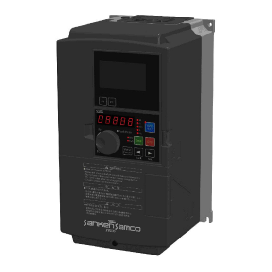
Product Body12
-
-
Top View14
-
Bottom View14
-
-
-
4 Wiring
23-
About Wiring24
-
-
-
6 Operation
67-
Test Run69
-
-
-
Output Frequency112
-
Torque Boost113
-
Base Voltage113
-
Base Frequency113
-
JOG Frequency117
-
Starting Method124
-
Start Delay Time126
-
Braking Method128
-
DC Braking Time129
-
DC Braking Force129
-
Rating Selection142
-
Low Torque Order167
-
System Function168
-
Copy Function168
-
Function Lock170
-
Motor Type176
-
Attentions182
-
Figure of Simple195
-
PID Function204
-
PID Operation212
-
VFPID Signal217
-
PIDLCK Signal217
-
IHOLD Signal218
-
ICLEAR Signal218
-
PID1EX Signal221
-
PID2EX Signal221
-
Message Checksum222
-
Parity Bit223
-
Stop Bit223
-
End Code223
-
Motor Parameters225
-
Starting Torque236
-
Torque Command238
-
Run Signal245
-
Zero Speed250
-
-
Outline258
-
-
Message Format264
-
Error Response272
-
BINARY Format273
-
Second Byte275
-
-
-
Batch Operation289
-
-
9 Fault Analysis
301 -
-
Inspection Items302
-
Part Replacement304
-
Megger Test308
-
-
14 EC Directives
323
Advertisement