
Related Manuals for Sanken Samco SVC06


Summary of Contents for Sanken Samco SVC06
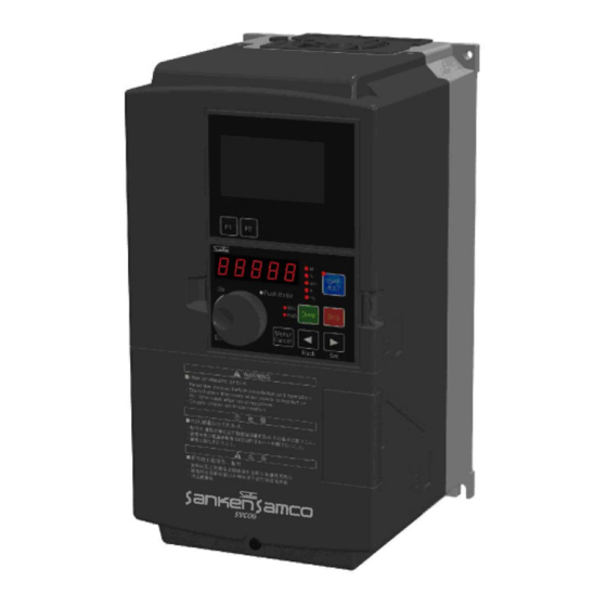
- Page 1 High Performance Vector Control Inverter Instruction Manual (Basic) SANKEN ELECTRIC CO., LTD.
- Page 3 Thank you for purchasing the Sanken High Performance Vector Control Inverter SVC06 series. This inverter is designed to drive an induction motor at a variable speed. The inverter has a built-in microprocessor providing a wide range of functions and easy operability. To ensure many years of trouble-free operation and maintain optimum performance, be sure to read through this manual before using the product.
-
Page 4: Table Of Contents
CONTENTS Safety Notes ............................- 5 - Important notes ........................- 5 - Notes on use ........................... - 5 - Notes on Installation ....................... - 6 - Notes on Handling and Moving ....................- 6 - Notes on Operation ......................... - 8 - Notes on Maintenance and Inspection ................... - Page 5 Names and Functions of Parts of the Operation Panel ............- 45 - 5-1-1 LCD display part of the operation panel ................ - 46 - 5-1-2 LCD operation part ......................- 46 - 5-1-3 LED display part ......................- 46 - 5-1-4 LED operation part ......................
- Page 6 10-2 Inspection Items ........................- 109 - 10-3 Part Replacement ........................ - 111 - 10-3-1 Fan Replacement ......................- 111 - 10-3-2 Smoothing Capacitors ....................- 115 - 10-4 Megger Test ........................- 115 - 10-5 Electrical measurement of main circuit ................- 116 - Specification ..........................
-
Page 7: Safety Notes
1. Safety Notes Important notes Danger Caution: risk of electric shock It is absolutely prohibited to remove the cover The risk of casualties exists because there are high-voltage circuits inside, accidental touch of which would cause electric shock. Caution: Fire Hazard!... -
Page 8: Notes On Installation
1–3 Notes on Installation Notes on Installation Caution It is absolutely prohibited to store or use the inverter under the environmental conditions described below. Failure to observe this warning may result in a fault, damage, or deterioration, which could lead to fire. ... - Page 9 1–5 Notes on Wiring 1-5 Notes on wiring Danger Wiring must be performed by qualified personnel. Failure to observe this warning may result in an electric shock or fire due to incorrect wiring. Do not connect AC power to an output terminal (U, V, or W). Failure to observe this warning may result in personal injury or fire.
-
Page 10: Notes On Operation
1–6 Notes on Operation Notes on Operation Danger Attach the front cover before turning the power on. And, do not remove the front cover when the power is on. Failure to observe this warning may result in electric shock. ... -
Page 11: Notes On Maintenance And Inspection
1–7 Notes on Maintenance and Inspection Notes on Maintenance and Inspection Caution Works such as maintenance, inspection and replacement of parts etc. can only be carried out by professional electricians. [Take off any metal item (such as watch, bracelet, etc.) before working on the equipment.] [Use insulated tools.] Failure to observe this warning may result in electric shock or burns. -
Page 12: Checking The Product And Precautions On Use
2. Checking the Product and Precautions on Use Checking the Product After unpacking the product, check the following: Check that the product has not been damaged during delivery, such as depression of casing etc.. If such problems are found, please contact the retailer. Danger ... -
Page 13: Precautions On Use
Precautions on Use Precautions on Use Use the product in a location satisfying the standard environmental specifications (temperature, humidity, vibration, dust, water drop, and toxic gases etc.). Before starting up the product for the first time, carefully check the wiring. Make sure that the power cable (input) and motor cable (output) are connected correctly. -
Page 14: Names Of Parts
Names of Parts Names of Parts [Top View] ① ② [Bottom View] Figure 2-2 Names of Parts Table 2-1 Names of Parts Name Function LCD display part Refer to [Chapter 5 Operation Panel] Operation Panel Refer to [Chapter 5 Operation Panel] Wiring Hole Refer to [Chapter 4 Wiring] Air Inlet... -
Page 15: Installation
3. Installation Installation Location and Storage This equipment is an electronic control device. Please pay full attention to environment of the device before it is used. Caution Mount the inverter on a metal surface or other non-flammable surface. Failure to observe this warning may result in a fire. ... - Page 16 Installation Location and Storage Table 3-2 (2) Capacity Modes Capacity Mode A Mode B 0900 90kW (150%) 110kW (120%) 1100 110kW (150%) 132kW (120%) 1320 132kW (150%) 160kW (120%) 1600 160kW (150%) 200kW (120%) 1850 185kW (150%) 220kW (120%) 2000 200kW (150%) 250kW (120%) 2200...
- Page 17 Installation Location and Storage Capacity Screws Recommended Screw Tightening Torque 4.3N•m -4 SVC06-0370 (2.3-5.6N•m) -4 SVC06-0450 10.8N•m -4 SVC06-0550 -4 (5.4-13.8N•m) SVC06-0750 -4 SVC06-0900 -4 SVC06-1100 -4 SVC06-1320 42N•m -4 SVC06-1600 -4 (35-50N•m) SVC06-1850 -4 SVC06-2000 -4 SVC06-2200 -4 SVC06-2500 - 15 -...
-
Page 18: Installation Direction And Space
Installation Direction and Space Installation Direction and Space (1) This inverter is of the wall mounting type. (2) Install the inverter vertically on a flat mounting surface. (3) Since the inverter generates heat, provide adequate space around it to ensure good heat dissipation conditions. -
Page 19: Removal And Installation Of The Front Cover
Removal and Installation of the Front Cover Removal and Installation of the Front Cover 3-3-1 Small-capacity model (SVC06-0015~0075-**2/SVC06-0007~0150-**4) (1) Removal of front cover (lower) Unscrew the M4 screws, and pull the cover toward you while pressing the Dent portion on both sides of the front cover (lower). -
Page 20: Middle-Capacity Model(Svc06-0185~0750-**4
Removal and Installation of the Front Cover (3) Installation When installing, work in reverse order. 3-3-2 Middle-capacity model(SVC06-0185~0750-**4) (1) Removal of front cover (lower) and internal sealing plate (iron) Unscrew the M4 screw on the front cover (lower) and pull down gently, and then the front cover (lower) will be removed. -
Page 21: Large-Capacity Model(Svc06-0900~2500-**4
Removal and Installation of the Front Cover 3-3-3 Large-capacity model(SVC06-0900~2500-**4) (1) Removal of front cover (lower) Unscrew the M4 screw, gently lift up and take off the cover. Please carry out this work during the main circuit wiring, control circuit wiring, and SW1 switching. Terminal block for control circuit... -
Page 22: Removal And Installation Of The Operation Panel
3-4 Removal and Installation of the Operation Panel Removal and Installation of the Operation Panel 3-4-1 Removal of Operation Panel Hook ① and ② on the cover with your fingers, and take off the panel, pull it toward you while pressing the jack catch on ②... -
Page 23: Wiring
Note 1: For SVC06 series inverter with built-in EMC filter, please place the EMC filter selector switch to ―ON‖. Note 2: See model selection samples of options of Sanken Inverter for related options. - 21 -... -
Page 24: About Wiring
About Wiring About Wiring Before carrying out wiring work, turn the inverter’s input power supply to ―OFF‖ (disconnected) first, and then check with a circuit tester that no applied voltage is present. Check also that the CHARGE lamp is not lit. - Page 25 About Wiring ● Do not share the grounding wire with the welding machine or the power equipment. ● Use the grounding wire prescribed in the technical standards for electrical equipment, and shorten wiring length as much as possible. ● Be careful not to loop the grounding wire when using multiple inverters. (a) Correct (b) Correct (c) Incorrect...
-
Page 26: Terminal Connection Diagram
Terminal connection diagram Terminal connection diagram Brake unit Note 7 (optional) DC reactor Brake resistor oputional oputional motor MCCB Main circuit Note 1 Single-phase 220V Grounding Groundig Note 1 ~ In operation 1 Multifunctional contact output Factory Preset: abnomal alarm signal Frequency matching... - Page 27 Terminal connection diagram Please use shielded wires for analog input and output wires, contact input wire (digital multi-function input terminals). (The set values of functional terminals are factory preset values.) In order to prevent misoperation due to interference, during wiring, signal lines and power lines should be separated as much as possible (about more than 10cm).
-
Page 28: Composition Of Main Circuit Terminals
Composition of Main Circuit Terminals Composition of Main Circuit Terminals 4-4-1 Description of Main Circuit Terminals Terminal Name Description Symbol R,S,T Input power Terminals connected to a three-phase commercial power supply supply terminals U,V,W Inverter output terminals Terminals connected to a three-phase induction motor P,P1 DC reactor connection Terminals connected to a DC reactor *1... -
Page 29: External Brake Resistor Selection Example
Composition of Main Circuit Terminals (4) SVC06-0900~1100-**4 (5)SVC06-1320~1850-**4 Option Option DC Reactor Brake unit DC Reactor Brake unit Motor Motor (6)SVC06-2000~2500-**4 DC Reactor Brake unit Option Motor 4-4-3 External brake resistor selection example 200V systems External brake resistor (recommended) External brake resistor (limit value) Model Resistance Capacity *1... - Page 30 Composition of Main Circuit Terminals 400V systems External brake resistor (recommended) External brake resistor (limit value) Model Resistance Capacity *1 Resistance Capacity *1 700Ω or more 380Ω or more 100W 150W SVC06-0007-4 320Ω or more 190Ω or more 200W 300W SVC06-0015-4 160Ω...
-
Page 31: Capacities Of Mccb And Mc And Wire Size
Composition of Main Circuit Terminals 4-4-4 Capacities of MCCB and MC and Wire Size 200V systems Control Main circuit Electromagnetic circuit contactor) MCCB Leakage Recommended wire size [mm Model circuit Tighte Max. Max. Rated Rated breaker) -ning wire wire making current current size... - Page 32 Composition of Main Circuit Terminals Control (Electromagnetic Main circuit circuit contactor) MCCB Recommended wire size [mm Max. (Leakage wire Model circuit Tighte Rated Max. size Rated breaker) -ning making wire current Input P and P1 Output current size torque wire wires wire [N•m]...
- Page 33 Composition of Main Circuit Terminals 4-4-5 Mould Case Circuit Breaker (MCCB) selection example 200V system Without DC reactor With DC reactor Mould Mould Case Motor earth leakage Case earth leakage Model Circuit Power circuit breaker Circuit circuit breaker Breaker Breaker (ELB) (ELB) (MCCB)
-
Page 34: Composition Of Control Circuit Terminals
4-5 Composition of Control Circuit Terminals Composition of Control Circuit Terminals 4-5-1 Wire size and terminal arrangement Terminal screw diameter: M3 Recommended wire size 0.75 [mm Tightening torque: 0.5[N•m] The arrangement of control circuit terminals is as shown in the following. +24V1 DCM2 +24V2 ACM2 VIF1... -
Page 35: Functions Of Control Circuit Terminals
Composition of Control Circuit Terminals 4-5-2 Functions of Control Circuit Terminals Table 4-3 Description of Control Circuit Terminals Terminal Type Terminal Name Function Description Rated Specification Notes Symbol Common terminals for digital input and Total DCM1 Digital signal output signals and for +24V1 and current consumed: DCM2 common terminals... - Page 36 4-5 Composition of Control Circuit Terminals Terminal Type Terminal Name Function Description Rated Specification Notes Symbol (1) By selecting a function code VIF1 Analog input VIF2 terminals corresponding to each function, VIF3 current / voltage of the 3 channels can be switched separately. (2) When the frequency setting is For voltage input: selected, the current / voltage input...
- Page 37 Composition of Control Circuit Terminals Terminal Terminal Type Function Description Rated Specification Notes Symbol Name (1) The Current output Current output range: (1) Adjust F1515 so that the current ACM1 terminals 4-20mA current output under proportional Load resistance: maximum output frequency output frequency of 500Ω...
-
Page 38: Multifunctional Input / Output
4-5 Composition of Control Circuit Terminals 4-5-3 Multifunctional Input / Output The so-called multifunctional input / output means freely assigning various functions to multifunctional input / output terminals through the data selection of function codes. The multifunctional input / output is divided into the input terminal of contact input and output terminal of open collector. -
Page 39: Control Logic Switching
Composition of Control Circuit Terminals 4-5-4 Control logic switching Through the switching of switches on the main control board, multifunctional input terminals DI1 - DI8 can be switched between SINK and SOURCE. When switching, use switch SW1 on the main control board. ... -
Page 40: Connection Of Control Circuit Terminals
Composition of Control Circuit Terminals ● When the transistor is used for external control signals, please set and wire transistors of different types as shown in the following table. Transistor Using internal power supply of the inverter Using external 24V power supply (*) NPN Type Set SW1 as SINK Unable to connect... - Page 41 Composition of Control Circuit Terminals 1) Potentiometer for frequency setting Please install a 5kΩpotentiometer of 0.3w or above, set the 1st speed frequency and select the frequency settings of current and voltage by selecting function code F1002. Please use shielded wires for wiring, please connect one end of the control terminal shield to the shield terminal ASG, while leave the other end open.
- Page 42 Composition of Control Circuit Terminals 3) Signal mode switching for emergency stop (multifunctional input ES terminal) The figure below shows an example of signal switching when the multifunctional input terminal is set for the external emergency stop (ES) command. ...
-
Page 43: Communication Function Terminal
Composition of Control Circuit Terminals 4-5-6 Communication function terminal RS485terminal block SOURCE RS485 communication The communication control with peripheral devices can be realized by using RS485 communication terminal block on the following main control board. SW2 is a switch for turning ON / OFF the terminating resistor. Please set only the farthest terminating resistor switch of the inverter to ON. -
Page 44: Connection Of Pg Sensor
Composition of Control Circuit Terminals 4-5-7 Connection of PG sensor 1) Connection example when the control terminal of main control board is used (open-collector mode) The power supply of PG sensor can be supplied by inverter Inverter Phase A pulse Phase B pulse Set function code F8109 (PG:PG output formation selection) to 1. -
Page 45: Installation And Wiring Of Optional Board
Installation and Wiring of Optional Board Installation and Wiring of Optional Board 4-6-1 Overview of Optional Board 2 optional boards can be installed on one inverter at the same time. 2 slots are provided in the inverter, but the shape of optional board may vary between different optional boards. -
Page 46: About Emc Filter
About EMC filter About EMC filter This inverter can be provided with built-in EMC filter (order requirement). Although the EMC filter can effectively reduce the interference transfer, it will increase the leakage current. ON or OFF of the EMC filter can be selected as follows through the on / off of the connector. Press the jack catch, release lock state And then the connector can be pulled freely... -
Page 47: Operation Panel
5. Operation Panel Names and Functions of Parts of the Operation Panel Display part (LCD) LCD panel part F1 key・ F2 key LED panel part LED Panel parts Monitor authorization display Monitor mode display 7-segment monitor Control authorization toggle key Operating mode display Drive key Stop key... -
Page 48: Lcd Display Part Of The Operation Panel
Names and Functions of Parts of the Operatin Panel 5-1-1 LCD display part of the operation panel The LCD display is a part of the LCD monitor. In conjunction with 7-segment monitor, the operation status and the function code settings etc. can be indicated. See 5-2-2 for display contents. 5-1-2 LCD operation part Key Name... -
Page 49: Switching Of Statuses
Switching of Statuses Switching of Statuses The operation panel has two display modes: [Status display mode] and [function code display mode], and the modes can be toggled by pressing the key Table 5-1 7-segment monitor display modes Display Mode Display Contents •... -
Page 50: Inverter Status Mode
Status Display Mode 5-3 Status Display Mode In status display mode, inverter status monitoring, alarm display, setting of output frequency and operations such as running and stop of inverter can be implemented. 5-3-1 Version display Shortly after the power-on of the equipment, the software version of inverter will be displayed on 7-segment monitor. The following is: display example for software version: VER 1.00. - Page 51 Status Display Mode Monitor mode display refers to the contents displayed on the 7-segment monitor Table 5-3 Display contents of monitor mode Display Contents Unit Display Contents Display of 7-segment Monitor Hz A rpm % M Frequency Running: the lit lamp indicates output frequency Stopped: the flashing lamp indicates set frequency...
-
Page 52: Alarm Display
Status Display Mode During selection of an operation command from an external terminal or from communication through the function code, as the key is pressed and held for about 2 seconds, running operation can be carried out instantly by the operation panel. -
Page 53: Frequency Input
Status Display Mode 5-3-4 Frequency input The frequency setting of the inverter can be input by using the quick knob with one of the following two methods. (1) Frequency setting A Turn the quick knob, and press when the required frequency is obtained, thus the frequency is changed. This is the method of frequency setting A. - Page 54 Status Display Mode (2) Frequency setting B Frequency setting B is a method for changing frequency by dialing the quick knob each time. This is an effective method for fine-tuning of the set frequency during observation of the load conditions. ...
-
Page 55: Function Code Display Mode
Function code display mode Function code display mode Function code display mode can be used to set various functions of inverter. 5-4-1 Status transition diagram 7-segment monitor Function block Function code Setting input display selection selection Status F10__ F1001 display OK:... -
Page 56: Basic Operation
Function code display mode 5-4-2 Basic operation The basic operation is used for changing the value of a function code. Operation example: setting F1414=10 Operation Display Description Display of status monitor (frequency display) Pressing the key shows the function block selection Turn the quick knob, then the function block number will change accordingly. -
Page 57: Confirming Operation
Function code display mode 5-4-3 Confirming operation For some function codes, operation needs to be re-confirmed to prevent data rewriting due to misoperation. Operation example: setting F1001=10 Operation Display Description Display of status monitor (frequency display) Press the key, the screen will display function block selection By turning the quick knob, you can select the target function module. -
Page 58: Signed Operation
Function code display mode 5-4-4 Signed operation For some function codes, they can be set with values containing signs (polarity). Operation example: setting F1503=-5.0 Operation Display Description Display of status monitor (frequency display) Press key, then the screen will display function block selection interface Turn the quick knob to select the target function module. -
Page 59: Special Functions
Special functions Special functions 5-5-1 Copy function operation The so-called copy function is the function which transfers the function code data to other inverters after transferring the function code data from one inverter side to the operation panel. The copy function is an effective function where several inverters need to be set with the same function code data. Only 1 inverter is set, while other inverters can also receive the same function code data, thus the same function code setting can be easily implemented. -
Page 60: Changed Code Display Operation
Special functions 5-5-2 Changed code display operation Considering current function code data may be different from the factory presets of product or the user's initial value, the function for displaying a changed function code and its data. This is an effective function for inquiring the difference between current function code and product’s factory preset or the user initial value. -
Page 61: Function Code Initialization Operation
Special functions 5-5-3 Function code initialization operation The inverter’s function code settings can be returned to factory presets through this function. Inverter’s initial value can be set to the factory preset or the data determined by the user (i.e. user’s initial value). Also, the initial value can be selected between the factory presets and the user’s initial value. -
Page 62: Alarm Contents Reading Operation
Special functions 5-5-4 Alarm contents reading operation Alarm history record display is a function for displaying alarms occurred in the past. The latest 5 alarms will be recorded. If a new alarm occurs, then the first alarm will be deleted. Operation example: reading alarm contents Operation Display... -
Page 63: Alarm Status Confirmation Operation
Special functions 5-5-5 Alarm status confirmation operation Alarm status confirmation is a function for displaying the inverter’s status when an alarm occurs. It can be used to confirm the latest 5 alarm statuses through function codes F1806 - F1810. If a new alarm occurs, then the first alarm will be deleted. - Page 64 Special functions 5-5-6 Serial number display A serial number display is a function which displays the serial number of the main part of an inverter on 7 segment monitor of an operation panel. The example of operation : When the serial number of an inverter is checked Operation Display Description...
-
Page 65: 7-Segment Monitor Display List
Special functions 5-5-7 7-segment monitor display list Monitor display Description During initialization, the data is displayed flashing. During initialization of user data, the data is displayed flashing. During confirmation of user data, the data is displayed flashing. The detonation indicates the need for reconfirmation operation using function code It is displayed flashing during search of the function code, of which the user data is discrepant from default settings. -
Page 66: Connecting Operation Panel With Extension Cable
Connecting operation panel with extension cable Connecting operation panel with extension cable If the operation panel is connected to inverter with the extension cable, then the operation panel can be installed in other instrument frame. (See Chapter 12: outside view of 12-2 Operation Panel for installation opening drawing). The extension cable length shall not be more than 5m. -
Page 67: Operation
6. Operation Wiring shall not be made after connecting to power supply. Failure to observe this warning may result in personal injury, fire or electric shock. Before undertaking the work, safety notes must be checked. Failure to observe this warning may result in personal injury or fire. ... -
Page 68: Operation Steps
6 – 1 Operation steps Operation steps The following flowchart shows all the operation steps before and after operation of the inverter. Please follow the following flow chart to carry out test run. Prepration starts Set up installation wiring 6-2-1 Confirmation before inspection before power... -
Page 69: Test Run
Test run Test run 6-2-1 Confirmation before power input ● Please check the following items after installation wiring and other works and before power-on. Table 6-1 Confirmation items before power input Item Content If the power supply voltage coincides with the inverter’s capacity and voltage. Power supply voltage confirmation Main wiring confirmation ... -
Page 70: Basic Setting (1)
Test run 6-2-3 Basic setting (1) Carry out setting after the basic operation settings have been confirmed. The selection of rated values can be made by switching through the following function code. Table 6-3 Basic function (1) Function Name Overload Maximum Remarks code... -
Page 71: Basic Setting (2)
Test run (5) Auto torque boost control The inverter is provided with voltage compensation function and slip compensation function. The former is used for auto-regulating the inverter output voltage, while the latter is used for slip frequency compensation based on the load. Use F2007 to select the above functions. - Page 72 Test run Before setting the above auto tuning, set the following function codes in order. Table 6-8 Auto tuning setting Function Code Content Settings Remarks F5001 Motor poles, voltage and XYZZZ capacity X: Polarity, Y : Rated voltage Z: Motor capacity F5002 Motor current rating 30 - 110% of the inverter...
- Page 73 Test run [Motor parameter auto tuning steps] (1) Setting of motor ratings Set all the motor ratings into function codes F5001 F5005 correctly. ・Please make function code display by pressing the key. ・After displaying the F5001 in the quick knob, please press the key.
- Page 74 Test run ② Setting of F5002 F5005 Set rated current, frequency, speed and insulation type of the connected motor. Under normal circumstances, please set according to the motor ratings. If the value set is incorrect, the motor parameters auto tuning results and the control characteristics of torque control will become adverse. Note 1): The settings are interdependent with the settings of motor poles, voltage and capacity (F5001).
- Page 75 Test run [Note: Notes on carrying out motor parameter auto tuning mode] ① Before carrying out auto tuning mode 2, be sure to disengage the load shaft of motor. If the load is not disengaged (for example, one-piece brake motor), then the auto tuning mode 2 can not carry out correct auto tuning.
-
Page 76: Basic Setting (3)
Test run 6-2-7 Basic setting (3) Please set the function codes used for setting the operation command and frequency command. Table 6-9 Basic function (2) Function code Name Content Remarks F1002 1st speed 1: Operation panel Please set the frequency 2: External analog VIF1 voltage (0-5 V) setting to values setting... -
Page 77: Operation Confirmation
Test run Operation command values can be changed using the status of multifunctional input terminals. According to the status of multifunctional input ROPE or RCOM, the operation commands as shown in the table below can be selected. See F1101. ROPE RCOM Operation Command terminal... - Page 78 Test run (3) Operation preparation After confirmation of test run and normal operation confirmation of motor, please implement the connection with the mechanical system. 1 Please set the function codes related to machine action. 2 Check the interface matched with peripheral mechanical equipment. (4) Operation confirmation Before delivery, various functions of the inverter have been set up as shown in the function code list.
-
Page 79: Special Functions
Special functions Special functions 6-3-1 JOG operation (1) Short-circuiting the multifunctional terminal JOG with DCM1, 2 forms a JOG operation mode. (2) For JOG operation, please set the F1101 = 2, and then short-circuit the multifunctional terminal FR or RR with DCM1, 2 after short-circuiting the multifunctional terminal JOG with DCM1, 2. -
Page 80: Notes On Free Run Stop Terminal (Mbs)
Special functions (2) When the external signal terminals are used to operate and stop the inverter, and you do not want the motor to automatically restart after recovery from a power failure, use the above circuit and set F1108=0. (3) When operating with the hold function, the inverter does not restart after recovery from the following conditions. -
Page 81: Definition Of Technical Terms
Definition of Technical Terms Definition of Technical Terms Output frequency Operation signal DC braking signal Main switching device drive signal Multifunctional output terminal operation 1 Multifunctional output terminal operation 2 DC braking DC braking Standby Stopped Running Stopped Figure 6-5 Operation action Table 6-12 Explanation of Terms Term Definition... -
Page 82: Function Code
7. Function Code Representation and Description of Function Codes By changing the function code, the inverter action can be changed. Function codes are functionally classified into "function blocks". To change the function code, first select the function block, and then select the serial number of the function code to be changed. A function code can be set through operation panel (see sections 5-4 and 5-5), or communication. -
Page 83: Function Code List
Function Code List - Basic Operation Functions Function Code List User Code Setting Factory Function Name Data Content Setting Resolution Presets Value Basic operation functions 1001 Motor control mode 1: V/f control mode selection 2: Speed control (speed sensorless vector control ) 3: Speed control (speed sensor vector control ) 4: Torque control (speed sensorless vector control ) 5: Torque control (speed sensor vector control ) - Page 84 Function Code List - Basic Operation Functions User Code Setting Factory Function Name Data Content Setting Resolution Presets Value 1007 Upper frequency limit 5-599Hz 0.01Hz 1008 Lower frequency limit 0.05-200Hz 0.01Hz 0.05 ※ 1 1009 Carrier frequency adjustment 0-130 1010 Acceleration/deceleration curve 1: Linear 2: S-shaped...
- Page 85 7-2 Function Code List - Basic Operation Functions User Code Setting Factory Function Name Data Content Setting Resolution Presets Value 1109 Direction of motor rotation 1: Forward and reverse run 2: Forward run only 3: Reverse run only 1110 Direction of motor rotation 1: Forward run (Operation panel) 2: Reverse run...
- Page 86 Function Code List – Input/Output-Related Functions User Code Setting Factory Function Name Data Content Setting Resolution Presets Value Input/Output-related function 1401 Bias frequency (VIF1) 0-±600 [Hz] 0.1 [Hz] (frequency at 0V or 4mA) 1402 Gain frequency (VIF1) 0-±600 [Hz] 0.1 [Hz] (frequency at 5V or 10V or 20mA) 1403 Bias frequency (VIF2)
- Page 87 Function Code List – Input/Output-Related Functions User Code Setting Factory Function Name Data Content Setting Resolution Presets Value 1414 Selection of input terminal DI1 0: Unused 1:FR, 2:RR, 1415 Selection of input terminal DI2 3:2DF, 4:3DF 1416 Selection of input terminal DI3 5:MBS,...
- Page 88 Function Code List – Input/Output-Related Functions User Code Setting Factory Function Name Data Content Setting Resolution Presets Value 1501 Internal analog output function 1 0: No function 1: Set frequency (Hz) 2: Output frequency [Hz] 3: PID1 feedback value [Hz] 4: PID2 feedback value [Hz] 5: Output current (A) 6: Output voltage [V]...
- Page 89 Function Code List – Input/Output-Related Functions User Setting Factory Code No. Function Name Data Content Setting Resolution Presets Value 1508 Frequency matching range 0-10Hz 0.01Hz 1509 Selection of output terminal DO1 0: Unused 1510 Selection of output terminal DO2 1: In operation 1 1511 Selection of output terminal DO3 2: Undervoltage,...
- Page 90 Function Code List – Input/Output-Related Functions User Setting Factory Code No. Function Name Data Content Setting Resolution Presets Value 1520 Current output function 0: No function 1: Set frequency (Hz) 2: Output frequency [Hz] 3: PID1 feedback value [Hz] 4: PID2 feedback value [Hz] 5: Output current (A) 6: Output voltage [V] 7: DC voltage [V]...
- Page 91 Function Code List – System-Related Functions User Setting Factory Code No. Function Name Data Content Setting Resolution Presets Value System-related functions 1601 Copy function 0: No function 1: Transfer the current code data to the operation panel 2: Transfer the contents stored by operation panel to the inverter (Excluding motor parameters measured ) 3: Transfer the contents stored by operation panel to the inverter (Including motor parameters measured )
- Page 92 7-2 Function Code List –Special Functions / Scheduled Operation Function User Code Setting Factory Function Name Data Content Setting Resolution Presets Value 1709 Feedback signal disconnection 0: Only warning 0.01s detection time 0.01 -119.99 sec. 120: No detection 1710 Carrier frequency variable by lowering 0: Disabled 1: Enabled temperature (Only when the A mode, function is...
- Page 93 7-2 Function Code List – Scheduled Operation Functions / Display Function User Setting Factory Code No. Function Name Data Content Setting Resolution Presets Value 2206 Operation timer T4 0 - 65,000 sec. 2207 Operation timer T5 0 - 65,000 sec. 2208 Operation timer T6 0 - 65,000 sec.
-
Page 94: Pid Function
Function Code List - Display Function / PID Function User Setting Factory Code No. Function Name Data Content Setting Resolution Presets Value LCD’s 1st display parameter setting 2303 0: No display LCD’s 2nd display parameter 2304 1: Frequency (Hz) 2305 setting 2: Output current (A) LCD’s 3rd display parameter setting... - Page 95 Function Code List – PID Function Setting User Code Factory Function Name Data Content Resoluti Setting Presets Value 3014 PID1 feedback value gain 0-50 0.01 3015 PID1 control proportional gain 0-100 0.01 (negative:F3012=2) 3016 PID1 control integral time 0.01 -100 sec. 0.01s (negative:F3012=2) 3017...
- Page 96 4005 Serial communication function 0:No function 1: Dedicated protocol communication function (SANKEN communication protocol) 2: Modbus communication function 4006 Inverter No. SANKEN protocol : 1 Modbus protocol : 0 4007 Communication speed 1: 1,200bps 2: 2,400bps 3: 4,800bps 4: 9,600bps...
- Page 97 7-2 Function Code List – Motor Parameters / Vector Control User Code Setting Factory Function Name Data Content Setting Resolution Presets Value Motor Parameters — ※ 1 5001 Motor poles, voltage and capacity X Y ZZZ X: Poles Y: Rated voltage Z: Motor capacity ※...
- Page 98 Function Code List – Vector Control / Torque Control Setting User Code Factory Function Name Data Content Resoluti Setting Presets Value 6007 Multiple for braking excitation current 0.01 2 (for applicable motor) ※ 1 6008 Braking excitation time 0: No braking excitation 0.1 s 0.1 -10 sec.
- Page 99 7-2 Function Code List - Extended Functions User Code Setting Factory Function Name Data Content Setting Resolution Presets Value 6121 Switching filter settings of speed - 0:Without filters torque 1-8:With filters Extended functions 8101 Point to Point control position limiter 1-32,767mm 32,767 8102...
- Page 100 7-2 Function Code List – Optional Functions / Other Functions The following values have been input from ※2-1 to ※2-8 in various models of inverters. ※ ※ ※ ※ ※ ※ ※ ※ Model F1012 F1013 F1014 F1015 F1016 F1017 F1018 F1019 SVC06-0015~0075-**2...
-
Page 101: Protection & Error Function
8. Protection & Error Function Operation error The operation error is displayed in the operation of operation panel (key, quick-turn knob), or some unallowed operations or code inputs in function code data inputting (operation, code input). When an operation error is displayed, the operation and code input are noneffective. ... -
Page 102: List Of Error Operation
Operation Error 8-1-1 List of error operation Table 8-1 List of error operation Monitor display Description The frequency cannot be set on the operation panel. Specify the undefined function code number. (not displayed on standard operation panel) The entered values exceed the allowable range. Or the motor parameters of F5001 (motor poles, voltage and capacity) are not registered. -
Page 103: Conflict & Interference Error
Conflict & Interference Error Conflict & interference error During function code entering, a conflict & interference error will be displayed when the entered data conflicts with the settings of other function codes. The displayed 4-digit number is the number of conflict & interference function code. - Page 104 Conflict & Interference Error Setting function code Error code Description Name Setting 1002 1st speed frequency setting 2-20 Exxxx Cannot set analog input repeatedly 26-28 E1001 When 1st speed frequency is pulse train input, the required PG sensor control mode cannot be used 1003 V/f pattern 2, 3...
- Page 105 Conflict & Interference Error Setting function code Error code Description Name Setting 3201 PID control action selection Beyond E1001 PID control action can only be used in V/f control or speed control E1901 Simple energy-saving mode and PID control operation cannot be used together E3203 Same PID control cannot be used both internally and...
-
Page 106: Warning Status
Warning Status Warning Status This warning status alerts you that the protection function of the inverter has been activated. However, the inverter keeps on running. If the inverter runs for a long time in this status, the inverter may enter the alarm status and stop running. -
Page 107: List Of Alarms
Alarm Status 8-4 Alarm Status The alarm status occurs when the protection function stops the inverter. During alarm status, all values on the display (Hz, A, rpm, %, M) flash indicating the alarm status. When Status Display mode is selected, details of the alarm are indicated on the 7-segment display. If the Status Display mode is not selected, details of the alarm are indicated on the 7-segment display if the alarm status continues after the Status Display mode is resumed. - Page 108 Alarm Status 7-segment Alarm description Check points Actions monitor display Radiator temperature Fan stopped? Check fan operation abnormality Ambient temperature too high? Increase the ventilation Undervoltage during Does power supply satisfy Examine/improve power supply acceleration conditions? conditions. Has the voltage dropped? Undervoltage during constant speed Undervoltage during...
- Page 109 Alarm Status 7-segment monitor Alarm description Check points Actions display Overspeed Over-shoot or under-shoot Confirm speed command value or happened? torque command value Modbus communication Communication cable Confirm communication cables are timeout disconnected? connected securely The abnormality Has not a +V terminal of a The resistance of potentiometer linked in a board control circuit terminal overload...
-
Page 110: Fault Analysis
9. Fault Analysis Problem Check points Voltages at input terminals R, S and T are normal? Motor does not Main circuit Is the motor wired correctly? rotate Load too heavy? Load side Motor locked? Starting frequency setting too high (F1103)? Operation panel ... -
Page 111: Maintenance & Inspection
10. Maintenance & Inspection Never touch the internal parts. Failure to obey may result in electrical shock, personal injury and other dangers. Careful checking and maintenance are essential to ensure that the general-purpose inverter SVC06 series can operate correctly with a long service life. 10-1 Precautions on Checking and Maintenance ... - Page 112 10-2 Inspection Items Inspection item Inspection details Method & Instrument Criteria No burning or breakage Visual inspection No abnormal Terminal board No liquid leakage Visual inspection No Main electrolytic leakage, No loosening of safety valve capacitor deformation or crack ...
-
Page 113: Part Replacement
10-3 Part Replacement Table 10-2 Main circuit power module checklist Input/Output Terminals Measured value Multimeter + Multimeter - Input (R, S, T) R, S, T Conducted R, S, T Not conducted R, S, T Not conducted R, S, T Conducted Output (U, V, W) U, V, W Conducted... - Page 114 10-3 Part Replacement (2) Steps for replacing fan of SVC06-0110 0150 The fan is on the top of the device. Step 1 Remove two screws (M3). Step 2 Hook the cover board with a finger and pull to remove it. Step 3 Pull out the fan and remove the connector, then make a replacement.
- Page 115 10-3 Part Replacement (4)Steps for replacing fan of SVC06-0370 ~0450 The fan is on the top of the device. Step 1 Remove four screws (M4×8). Step 2 Pull out the cover board with a hand. Step 3 Remove two screws (M4×60). Step 4 Pull out the fan and remove the connector, then make a replacement.
- Page 116 10-3 Part Replacement (6)Steps for replacing fan of SVC06-0900 ~2500 The fan is on the top of the device. Step 1 Remove the screws (M4). Step 2 Pull out the cover board with a hand. Step 3 Remove the screws and the connector. After the replacement, reinstall the fan with a sequence of 3 →2→...
-
Page 117: Smoothing Capacitors
10-3 Part Replacement 10-3-2 Smoothing Capacitors Aluminum electrolytic capacitors for smoothing deteriorate over time. It must be replaced approximate every ten years. Since the service life varies greatly depending on the ambient temperature, load and using frequency, this time period is only an approximate limit rather than a guaranteed limit. When used continuously in a high temperature (averagely 40℃... -
Page 118: Electrical Measurement Of Main Circuit
10-5 Electrical Measurement of Main Circuit 10-5 Electrical measurement of main circuit Since the voltages and currents of the main inverter circuit at the input (power supply) and output (motor) contain harmonic components, measured values may differ depending on the meter used. When using a commercial frequency meter, select one of the types listed in the table below. -
Page 119: Specification
11. Specification 11-1 Standard specification 200V Item Specification Model(SVC06-□□□□-2) 0015 0037 0075 Standard applicable motor [kW] Rated capacity [kVA] 12.6 Mode A Rated current [A] 17.6 Heavy overload Overload current rating 150%-1min Output frequency range 0.05 599Hz(Starting frequency 0.05 60Hz variable) Standard applicable motor [kW] Rated capacity [kVA] 16.8... - Page 120 11-1 Standard Specification 400V Item Specification Model(SVC06-□□□□-4) 0007 0015 0022 0040 0055 0075 0110 0150 Standard applicable motor [kW] 0.75 Rated capacity [kVA] 11.8 17.3 22.2 Mode A Heavy Rated current [A] 12.6 overload Overload current rating 150%-1min Output frequency range 0.05 599Hz(Starting frequency 0.05 60Hz variable)...
- Page 121 11-1 Standard Specification Item Specification Model(SVC06-□□□□-4) 0185 0220 0300 0370 0450 0550 0750 Standard applicable motor [kW] 18.5 Rated capacity [kVA] Mode A Heavy Rated current [A] overload Overload current rating 150%-1min Output frequency range 0.05-599Hz(Starting frequency 0.05-60Hz variable) Standard applicable motor [kW] Rated capacity [kVA] Mode B Light...
- Page 122 11-1 Standard Specification Item Specification Model(SVC06-□□□□-4) 0900 1100 1320 1600 1850 2000 2200 2500 Standard applicable motor [kW] Rated capacity [kVA] Mode A Heavy Rated current [A] overload Overload current rating 150%-1min Output frequency range 0.05-400Hz(Starting frequency 0.05-60Hz variable) Standard applicable motor [kW] Rated capacity [kVA] Mode B Light...
-
Page 123: Inverter General Specification
11-2 Inverter General Specification 11-2 Inverter general specification Vector control ∕ sensorless vector control ∕ V/f control Control mode With PG sensor 0.05Hz-240Hz(1:1000/50Hz reference) Speed control range Without PG sensor 0.25Hz-240Hz(1:200/50Hz reference) With PG sensor Response characteristic: 250rad/sec Precision: ±0.01% Speed Response/precision Without PG sensor... -
Page 124: Communication Function Specification
11-3 Communication Function Specification 11-3 Communication function specification RS485 communication Electrical characteristics Modbus-RTU Communication protocol SANKEN protocol communication protocol 4-wire / 2-wire bus type Communication type (RS485 standard) Transmission distance Total 500m, terminal resistor is required Number of units Max. 32 Max. -
Page 125: External Dimension
12. External Dimension 12-1 Master dimension Table 12-1 List of overall dimension Capacity SVC06-0015-2 SVC06-0037-2 SVC06-0075-2 SVC06-0007-4 SVC06-0015-4 SVC06-0022-4 SVC06-0040-4 SVC06-0055-4 SVC06-0075-4 SVC06-0110-4 SVC06-0150-4 (unit:mm) - 123 -... - Page 126 12-1 Master Dimension Table 12-2 List of overall dimension Capacity SVC06-0185-**4 SVC06-0220-**4 SVC06-0300-**4 SVC06-0370-**4 SVC06-0450-**4 SVC06-0550-**4 SVC06-0750-**4 (unit:mm) - 124 -...
- Page 127 12-1 Master Dimension Table 12-3 List of overall dimension W2 Capacity SVC06-0900-**4 SVC06-1100-**4 SVC06-1320-**4 SVC06-1600-**4 1010 SVC06-1850-**4 SVC06-2000-**4 1010 SVC06-2200-**4 SVC06-2500-**4 (unit:mm) - 125 -...
-
Page 128: Operation Panel
12-2 Operation Panel 12-2 Operation panel (1) Operation panel 3-M3 screw length: 4mm or shorter (unit:mm) (2) External installation of operation panel: Dimensional diagram of opening hole (unit:mm) - 126 -... -
Page 129: Dc Reactor Dimension
12-3 DC reactor dimension 12-3 DC reactor dimension Subsidiary DC capacity reactor type SVC06-0900-**4 DCL-250020 4-9φ×15L SVC06-1100-**4 DCL-300017 SVC06-1320-**4 DCL-350013 SVC06-1600-**4 DCL-450011 SVC06-1850-**4 DCL-550009 4-9φ×25L SVC06-2000-**4 DCL-550009 SVC06-2200-**4 DCL-630008 SVC06-2500-**4 DCL-690007 (unit:mm) - 127 -... -
Page 130: Peripheral Equipments & Options
13. Peripheral Equipments & Options Please work on the equipment only when the safety precautions are confirmed. Failure to observe may result in personal injury and fire. The followings are options for SVC06 series. Please configure the peripheral equipments (including options) according to the situation and purpose. - Page 131 Peripheral equipments & options The following optional boards built into the inverter are available. Table 13-2 Optional Card Option Name Type Function Applicable inverter PG Option card SC-PG1 Detect and feedback the motor speed with the detector (PG), to SVC06 all models operate speed control function and position control function.
-
Page 132: 14: Ec Directives
14: EC Directives The inverter meets the requirements stipulated in low voltage directive 2006/95/EC. The inverter is tested based on EN 61800-5-1:2007. In case of installation in machines, startup of the drive inverters (i.e. start of designated operation) is prohibited until it is determined that the machine meets the requirements stipulated in the EC Directive, observe EN 60204. - Page 133 Memorandum...
- Page 134 Memorandum...
- Page 136 It after confirming the unit software version, download the instruction manual from the following website, will made please confirm the content. You may not have instruction manual that can be downloaded by the software version. http://www.sanken-ele.co.jp/prod/powersp/invert/index.htm SANKEN ELECTRIC CO., LTD. URL http://www.sanken-ele.co.jp Address: 1-11-1 Nishi-Ikebukuro, Toshima-ku, Tokyo Phone: +81-3-3986-6157 Fax: +81-3-3986-2650 Published in November 2013 Corresponding software version: VER-3.04 or later...
Need help?
Do you have a question about the Samco SVC06 and is the answer not in the manual?
Questions and answers