Sam4s ER-180T SERIES Service Manual
Hide thumbs
Also See for ER-180T SERIES:
- Operation and programming manual (92 pages) ,
- Operator's and programming manual (89 pages) ,
- Quick setup manual (6 pages)
Table of Contents
Advertisement
SERVICE
ELECTRONIC CASH REGISTER
ELECTRONIC CASH REGISTER
ER-180T SERIES
Manual
1.
Precaution Statements
2.
Product Specifications
3.
Installation and Operation
4.
Assembly and Disassembly
5.
Exploded View and Parts List
6.
PCB Layout and Parts List
7.
Block Diagram
8.
Wiring Diagram
9.
Schematic Diagrams
C O N T E N T S
Advertisement
Table of Contents

Related Manuals for Sam4s ER-180T SERIES


Summary of Contents for Sam4s ER-180T SERIES
- Page 1 ELECTRONIC CASH REGISTER ER-180T SERIES SERVICE Manual ELECTRONIC CASH REGISTER C O N T E N T S Precaution Statements Product Specifications Installation and Operation Assembly and Disassembly Exploded View and Parts List PCB Layout and Parts List Block Diagram...
- Page 2 About this Manual This service manual describes how to perform hardware service maintenance for the SAM4S ER-180T Series Electronic Cash Register. Notes Notes may appear anywhere in the manual. They describe additional information about the item. Precaution symbols . Indicates a Safety Precaution that applies to this part component.
- Page 3 This manual may not, in whole or in part, be copied, photocopied, reproduced, translated or converted to any electronic or machine readable from without prior written permission of Shin Heung Precision . SAM4S ER-180T SERIES Service Manual First edition. March 2010. V1.0 Printed in KOREA...
- Page 4 Overview of this ECR This ECR is a microprocessor-based system, using an 8 bits microprocessor. This service manual provides the technical information for many individual component systems, circuits and gives an analysis of the operations performed by the circuits. If you need more technical information, please contact our service branch or R&D center.
-
Page 5: Precaution Statements
Remplacer uniquement avec une batterie du même recommended by the manufacturer. type ou d’un type équivalent recommandé par le Dispose used batteries according to the constructeur. manufacturer’s instructions. Mettre au rebut les batteries usagées conformément aux instructions du fabricant. SAM4S ER-180T SERIES... -
Page 6: Servicing Precautions
5. Use only a grounded-tip soldering iron when soldering or unsoldering ESDs. 6. Use only an anti-static solder removal device. Many solder removal devices are not rated as anti-static; these can accumulate sufficient electrical charge to damage ESDs. SAM4S ER-180T SERIES... -
Page 7: Product Specifications
• 420(L) X 325(W) X 202(H) With B-Drawer & Bplus Drawer Dimensions(mm) • 450(L) X 400(W) X 218(H) With G-Drawer (Option) • 3.8Kg (SET only) With B-Drawer & Bplus Drawer Weight • 8.1Kg (SET only) With G-Drawer (Option) Table2-1 General Specifications SAM4S ER-180T SERIES... -
Page 8: Printer Specification
• 8(W) × 12(H) Font (Including a horizontal) Character Structure • 1.5 mm(W) ×3.0 mm(H) Character Size • 2.0 mm Column Pitch • 3.875 mm (Including 3.5-dot line spacing) Line Pitch • 16 (8×12 Dots/Character) Number of Column Table2-4 Character Specification SAM4S ER-180T SERIES... -
Page 9: Ecr Features
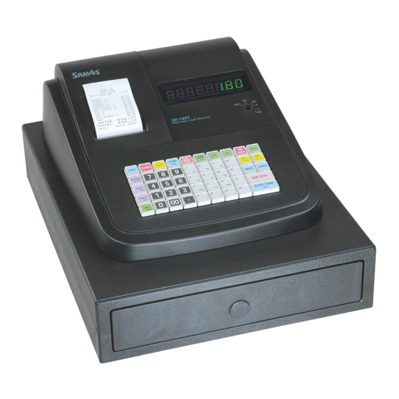
2-2 Appearance A. Appearance Dimensions (mm) Figure2-1 Dimensions B. ECR Features ① Cover Printer ② Key Board ③ Cash Drawer ④ Cover Display ⑤ Power Jack ⑥ Mode Switch ⑦ Front Display ⑧ Rear Display(Option) Figure2-2 Location Feature SAM4S ER-180T SERIES... - Page 10 2. Product Specifications Memo SAM4S ER-180T SERIES...
-
Page 11: Installation
6. Turn the Spool Winding in 2~3 turns. (Fig 3-1 (H)) 7. Place the Spool Winding on the Paper Supply. If it loosen, turn to tighten it. (Fig 3-1 (I)) 8. Replace the printer cover.(Fig 3-1 (J)) Figure 3-1. Paper Installation and Take-Up Spool Installation SAM4S ER-180T SERIES... - Page 12 Warning: Only use Cigar-Jack Power. Do not connect AC Power Cord. Description 1. Use the Cigar Jack cable. (CIGAR JACK CABLE) 1. Insert the CIGAR JACK CABLE like below figure. 2. Connect the 3 Pin connector of the CIGAR JACK CABLE for a Vehicle Battery. SAM4S ER-180T SERIES...
-
Page 13: Program Download
3. Installation and Operation 3-1-3. Program Download Description DOWNLOAD CABLE for Program Update. (Special Cable for ER-180/180T) ( DOWNLOAD CABLE ) Disassemble the cover printer Disassemble the screw. SAM4S ER-180T SERIES... - Page 14 3. Installation and Operation 3-1-3. Program Download Description Disassemble the drawer. Disconnect the drawer harness and compulsory harness. Disassemble the drawer. SAM4S ER-180T SERIES...
- Page 15 3. Installation and Operation 3-1-3. Program Download Description Insert the download cable. Insert the DC power cord. SAM4S ER-180T SERIES...
- Page 16 Run the Flash Development Tool Kit Basic. ( You should install this program first) Type “M3030RFCP” in the Filter Edit box and select ‘M16C _M3030RFCP’ and press “Next” button. Select connected port of your PC and press “Next button”. SAM4S ER-180T SERIES...
- Page 17 3. Installation and Operation 3-1-3. Program Download Description select communication speed. Uncheck “Use default” and set “115200” to the “Recommended speeds” and press “Next button”. Press “Finish”button. SAM4S ER-180T SERIES...
- Page 18 3. Installation and Operation 3-1-3. Program Download Description Click the Options menu and check the “AutoDisconnect” Select the downloaded file. Check the Download File and “User/Data Area”. Press arrow button and open “180T.mot”file. SAM4S ER-180T SERIES...
- Page 19 3. Installation and Operation 3-1-3. Program Download Description After selecting downloaded file then press “Program Flash”. If you see “ID Check” dialog, then press OK. See the progress bar is going as below picture. SAM4S ER-180T SERIES...
- Page 20 Unplug the DC power cord. Unplug the download cable Reassemble drawer and assemble the screw as original status. Plug the DC power cord. Do the RAM ALL CLEAR and program other settings again (date and time..) 3-10 SAM4S ER-180T SERIES...
-
Page 21: Operation
Use for normal registrations. Use to read register reports and perform other manager functions. Use to read register reports and reset totals to zero. Use to program the register Use for H/W tests and special setting. Table3-1 Mode Function SAM4S ER-180T SERIES 3-11... -
Page 22: Key Board Matrix
4. While continuing to hold the “SUB TOTAL” key, plug the register into a power source. 5. The message "****** INITIAL CLEAR ******” prints when the initial clear is complete. ****** INITIAL CLEAR ****** Figure3-3. Initial Clear Key & Print Sheet 3-12 SAM4S ER-180T SERIES... - Page 23 = = = = = = = = = = = = = = = = = == = RAM 1Mbits OK ER-180T EPROM INFO. VERSION : STD 01.000 CHECKSUM : 2DEB 2009 CLERK 00 000001 00000 Figure3-4. All Clear Key Sequence & Print Sheet SAM4S ER-180T SERIES 3-13...
-
Page 24: Self Test
As you press each key. The Display shows the key’s location code. 3-2-5-(d) Test Mode Switch 1. Turn the Mode switch to Service Mode position. 2. Press Press ‘1’, ‘3’ and ‘SUB TOTAL’ key on key board. 3. Turn the Mode key and check the display. 3-14 SAM4S ER-180T SERIES... -
Page 25: Assembly And Disassembly
10. Separate the COVER DISPLAY(’)from the CASE UPPER(⑫). (Page 5-1) 11. Remove two screws (⑩) on the CASE UPPER (⑫) and Separate the MODE SWITCH(⑬), from the CASE UPPER(⑫). (Page 5-1) B. Reassembly Procedure - Reassembly procedure is in reverse order. SAM4S ER-180 SERIES... - Page 26 4. Assembly and Disassembly Memo SAM4S ER-180 SERIES...
-
Page 27: Exploded View And Parts List
5 Exploded View and Parts List [Exploded View] A.ASS’Y MAIN C. KEYBOARD B.DRAWER Figure 5-1. Total Disassembly SAM4S ER-180T SERIES... - Page 28 KEYBOARD + KBD HOUSING JK72-20389A PMO-KBD HOUSING JK72-20016A PMO-GUIDE WINDING OPTION JK44-30507A ADAPTOR:EUROPE JK44-30507B ADAPTOR:USA JK44-30507C ADAPTOR:AUSTRALIA JK44-30507D ADAPTOR:UK JK59-20016A UNIT-PRINTER 6002-000174 SCREW-TAPPING:PWH,M3,L10 C/UPPER + CIGAR PCB OPTION JK39-40805A HARNESS-CIGAR JACK OPTION JK92-01649A PBA-CICARJACK:ER-180,OPTION OPTION JK72-20376D PMO-CASE UPPER OPTION SAM4S ER-180T SERIES...
- Page 29 5. Exploded View and Parts List B. DRAWER (B-TYPE) – BOTTOM : MOLD LOCK Figure 5-2. B-TYPE DRAWER (BOTTOM : MOLD LOCK) SAM4S ER-180T SERIES...
- Page 30 B. DRAWER (B-TYPE) – BOTTOM : MOLD LOCK Figure 5-3. Lubrication Points of the B-TYPE Drawer ( BOTTOM : MOLD LOCK ) Code No. Description / Specification Q`ty Serviceable Remark 0201-002010 GREASE-N2 Minimum Serviceable Packing Weight : 40g SAM4S ER-180T SERIES...
- Page 31 ASS’Y BOTTOM Parts-No. Description/Specification Q'ty Design-Location Serviceable Remark JK70-50115A SCREW-TAPPING SPECIAL 6107-001041 SPRING-LOCK LEVER JK72-20387A PMO-LATCH 1 JK72-20388A PMO-LATCH 2 JK33-10501A SOLENOID-DC JK72-40375C PMO-COVER BOTTOM JK61-40201A FOOT 6002-000175 SCREW-TAPPING 6021-000225 NUT-HEXAGON 6031-000243 WASHER-PLAIN JK75-10386A MEC-ROLLER JK70-30024A SPRING-PUSH SAM4S ER-180T SERIES...
- Page 32 5. Exploded View and Parts List B. DRAWER (B-TYPE) – BOTTOM : STEEL LOCK Figure 5-2. B-TYPE DRAWER ( BOTTOM : STEEL LOCK ) SAM4S ER-180T SERIES...
- Page 33 Figure 5-3. Lubrication Points of the B-TYPE Drawer ( BOTTOM : STEEL LOCK ) Code No. Description / Specification Q`ty Serviceable Remark 0201-002010 GREASE-N2 Minimum Serviceable Packing Weight : 40g 0201-002009 GREASE-N1 Minimum Serviceable Packing Weight : 40g SAM4S ER-180T SERIES...
- Page 34 MEA-UNIT LOCK(7V,COM) 6001-000525 SCREW-MACHINE: M3,L14 6107-001041 SPRING-LOCK LEVER JK70-50079A SCREW-TAPTITE: M3,L5 JK97-01080B MEC-SUB LOCK JK27-10500C SOLENOID-DC: 7V JK72-40375C PMO-COVER BOTTOM JK61-40201A FOOT 6002-000175 SCREW-TAPPING 6021-000225 NUT-HEXAGON 6031-000243 WASHER-PLAIN JK75-10386A MEC-ROLLER JK70-30019A SPRING-PUSH JK70-50090A PLAIN-WASHER JK70-50092A SCREW-TAPTITE: M5,L10 SAM4S ER-180T SERIES...
- Page 35 5. Exploded View and Parts List B. DRAWER (G-TYPE) Figure 5-4. G-TYPE DRAWER SAM4S ER-180T SERIES...
- Page 36 5. Exploded View and Parts List B. DRAWER (G-TYPE) Figure 5-5. Lubrication Points of the G-TYPE Drawer Code No. Description / Specification Q`ty Serviceable Remark 0201-002010 GREASE-N2 Minimum Serviceable Packing Weight : 40g 0201-002009 GREASE-N1 Minimum Serviceable Packing Weight : 40g 5-10 SAM4S ER-180T SERIES...
- Page 37 Design-Location Serviceable Remark JK97-20093K MEA-UNIT LOCK(7V) JK97-20093L MEA-UNIT LOCK(7V,COM) JK27-10500C SOLENOID-DC: 7V 6001-000525 SCREW-MACHINE: M3,L14 JK70-50079A SCREW-TAPTITE: M3,L5 JK39-40301R CBF HARNESS MICRO S/W 6107-001041 SPRING-LOCK LEVER JK97-01080B MEC-SUB LOCK JK70-30019A SPRING-PUSH JK70-50090A PLAIN-WASHER JK70-50092A SCREW-TAPTITE: M5,L10 SAM4S ER-180T SERIES 5-11...
- Page 38 1SET OPTION JK75-20041A MEC-KEY LOCK: #2424 OPTION JK70-20120A IPR-DUMMY KEY OPTION JK70-20074A IPR-LEVER LOCK OPTION 6044-000124 RING-E: ID3 OPTION JK70-20116A IPR-LEVER PUSH OPTION JK70-40905A ICT-SHAFT LEVER PUSH OPTION JK70-30020A SPRING-LEVER PUSH OPTION 6044-000231 RING-E: ID5 OPTION 5-12 SAM4S ER-180T SERIES...
- Page 39 5. Exploded View and Parts List C. ASS’Y KEYBOARD (LASER PRINTING TYPE) Figure 5-6 ASS’Y KEYBOARD (LASER PRINTING TYPE) SAM4S ER-180T SERIES 5-13...
- Page 40 Design-Location JK59-30041A UNIT-KEYBOARD: ER-180T(STD) JK81-20085A PMO-KEY TOP 1×1 JK81-20086A PMO-KEY TOP 1×2 JK81-20094A PMO-KEY TOP SET:0~9 JK81-20084A PMO-KEYBOARD FRAME JK81-20092A REX-CONTACT RUBBER JK81-20083A ASSY-FPC,230 JK81-20091A IPR-BOTTOM PLATE JK81-20076A SCREW TAPPING(BH):M2X5 JK81-20095A BALANCE-BAR JK72-20390A PMO-BLANK KEY TOP 5-14 SAM4S ER-180T SERIES...
- Page 41 5. Exploded View and Parts List C. ASS’Y KEYBOARD (LABEL TYPE) Figure 5-7 ASS’Y KEYBOARD (LABEL TYPE) SAM4S ER-180T SERIES 5-15...
- Page 42 JK81-20089A PMO-KEY TOP 1×1 JK81-20090A PMO-KEY TOP 1×2 JK81-20087A PMO-KEY CAP 1×1 JK81-20089A PMO-KEY CAP 1×2 JK81-20095A BALANCE-BAR JK81-20084A PMO-KEYBOARD FRAME JK81-20092A REX-CONTACT RUBBER JK81-20083A ASSY-FPC,230 JK81-20091A IPR-BOTTOM PLATE JK81-20076A SCREW TAPPING(BH):M2X5 JK72-20390A PMO-BLANK KEY TOP 5-16 SAM4S ER-180T SERIES...
-
Page 43: Pcb Layout And Parts List
2003-000327 R-METAL OXIDE:51ohm,5%,2W,5.4*14.7mm, 2401-000042 C-AL:100uF,16V,RADIAL,φ6.3*7L,RoHS 2401-000700 C-AL:2200uF,20%,10V,RADIAL,φ10*20L 2801-003376 CRYSTAL-UNIT:32.768KHz,20ppm,28-AAY,12 3002-001027 BUZZER-PIEZO:85dB,1.5V,24mA,2.048KHz,BK 3601-000261 FUSE-CARTRIDGE:250V,3.15A,TIME-LAG,GLASS 3602-000001 FUSE-CLIP:-,-,30mohm 3708-000306 CONNECTOR-FFC:6P,1R,2.54mm,ST,BLACK 3708-000327 CONNECTOR-FFC:8P,1R,2.54mm,ST,BLACK 3708-001418 CONNECTOR-FFC:16P,1mm,ST,DIP,TOP,IVORY 3708-001419 CONNECTOR-FFC:24P,1mm,ST,DIP,TOP,IVOR, CN11 3711-003968 CONNECTOR-HEADER:BOX,3P,1R,2.5mm,ST 3711-003969 CONNECTOR-HEADER:BOX,2P,1R,2.5mm,ST 3711-003409 CONNECTOR-HEADER:BOX,3P,1R,2mm,ST 3711-003420 CONNECTOR-HEADER:BOX,5P,1R,2mm,ST CN10 3711-004100 WAFER;BOX-HEADER,1R,2P,2.5mm,ST,WHITE 3711-004104 WAFER;BOX-HEADER,1R,3P,2.5mm,ST,WHITE SAM4S ER-180T SERIES... - Page 44 R53,R55 2008-000030 R-CHIP:2KOHM,5%,1/10W,1608 R5,R6,R9R10 R2,R23,R24,R25,R30,R32, 2008-000037 R-CHIP:4.7KOHM,1%,1/10W,1608,1% R35,R40,R43 2008-000041 R-CHIP:6.8KOHM,1%,1/10W,1608,1% R1,R8,R12,R13,R15,R22, R26-R29,R31,R33,R34, 2008-000044 R-CHIP:10KOHM,1%,1/10W,1608,1% R37,R41,R42,R44,R45, R49,R54 2008-000046 R-CHIP:15KOHM,5%,1/10W,1608 R11,R46 2008-000063 R-CHIP:100KOHM,5%,1/10W,1608 2008-000065 R-CHIP:150KOHM,1%,1/10W,1608,1% 2011-001099 R-NETWORK;1KOHM,5%,1/16W,L,CH RA2,RA3 2011-001100 R-NETWORK;4.7KOHM,5%,1/16W,L,CH RA5,RA8 2011-001101 R-NETWORK;10KOHM,5%,1/16W,L,CH RA1,RA4,RA6,RA7 2204-000003 C-CERAMIC,CHIP:15pF,5%,50V,1608 2204-000004 C-CERAMIC,CHIP:22pF,5%,50V,1608 C8,C13 SAM4S ER-180T SERIES...
- Page 45 C-TANTAL:10uF,16V,3528 2801-003382 CRYSTAL-SMD:14.7456MHZ,SX-1,18pF 3711-004123 WAFER;BOX-HEADER,1R, 8P,1.25mm,SMD JK41-10781A PCB-MAIN:ER-180T,FR-4,2L,T1.6 6-2 FRONT DISPLAY PCB Part-No Description / Specification Q’TY Design Location Serviceable Remarks JK92-01648A PBA-DISPLAY:ER-180,FRONT ASSY 3708-001417 CONNECTOR-FFC:16P,1mm,AN,DIP,UPSIDE,IVR, JK07-00018A DISPLAY-FND:ER180,FND*4,12PIN,Y/G U1,U2 2001-000027 R-CARBON:100OHM,5%,1/4W,AA,TP,2.4X6.0MM R1-R8 JC39-40511A CBF HARNESS:ML-80,JUMPER,AWG22,52mm,SILV JK41-10782A PCB-DISPLAY:ER-180,FRONT,FR-1,T1.6 SAM4S ER-180T SEIRES...
- Page 46 6. PCB Layout and Parts List 6-3 DUAL DISPLAY PCB Part-No Description / Specification Q’TY Design Location Serviceable Remarks JK92-01647A PBA-DISPLAY:ER-180,DUAL ASSY 3708-001417 CONNECTOR-FFC:16P,1mm,AN,DIP,UPSIDE,IVR, JK07-00018A DISPLAY-FND:ER180,FND*4,12PIN,Y/G U1-U4 JK39-40804A HARNESS-JUMP WIRE:ER180,80mm,8P,DISPLAY DISPLAY HAR. 2001-000027 R-CARBON:100OHM,5%,1/4W,AA,TP,2.4X6.0MM R1-R16 JC39-40511A CBF HARNESS:ML-80,JUMPER,AWG22,52mm,SILV J1-J10 JK41-10783A PCB-DISPLAY:ER-180,DUAL,FR-1,T1.6 SAM4S ER-180T SERIES...
- Page 47 Design Location Serviceable Remarks JK92-01649A PBA-CIGARJACK:ER-180,OPTION ASSY 2401-000032 C-AL:100uF,50V,RADIAL,φ8*11.5L,RoHS 2401-000042 C-AL:100uF,16V,RADIAL,φ6.3*7L,RoHS 3603-000004 POLY-SW;RUEF160,30V,1.6A,DIP,RADIAL 3711-000823 CONNECTOR-HEADER:BOX,3P,1R,2.5mm,ANGLE 3711-004099 WAFER;BOX-HEADER,1R,3P,2.5mm,AN,WHITE, JK39-40805A HARNESS-CIGA JACK:ER180,3P,140mm 0404-001051 DIODE-SCHOTTKY:SK14,40V,1A,DO-214AA, D1,D2 1203-001776 IC-REGULATOR:AP1501-K5L,TO263-5L,SMD,ADJ 2007-000297 R-CHIP:10KOHM,1%,1/8W,DA,TP,2012 2007-000671 R-CHIP:2KOHM,5%,1/8W,DA,TP,2012 2203-000192 C-CERAMIC,CHIP:100nF,+80-20%,50V,Y5V,TP, C1,C2 JK27-60102A L-COIL:BDS-1055R,33uH,SMD,IND-330M-SM-12 JK41-10784A PCB-CIGAR JACK:ER-180,FR-4,2L,T1.6 SAM4S ER-180T SEIRES...
- Page 48 6. PCB Layout and Parts List Memo SAM4S ER-180T SERIES...
-
Page 49: Block Diagram
M3030RFCPFP BS62LV1006 (1Mbit) TPH SIGNAL(CLK,SDI,LAT,STB#1) GPIO GPIO nCS SRAM#1 nCS1 BUZZER(2KHZ) VBAT TIMER 2 DRIVER SCLK 32.768KHZ GPIO RTC IC GPIO PCF8563 DRAWER DRAWER#1 DRAWER GPIO (MOLEX) DRIVER nINT3 COMP SENS COMP BCLK GPIO XOUT (MOLEX) 14.7456MHZ SAM4S ER-180T SEREIS... - Page 50 7. Block Diagram Memo SAM4S ER-180T SEREIS...
-
Page 51: Wiring Diagram
Signal Name Pin No Signal Name Pin No Signal Name SEN_DWRCOMP CN5 (KEYSCAN) Pin No Signal Name Pin No Signal Name Pin No Signal Name KEYSCAN #2 KEYSCAN #6 KEYSCAN #4 KEYSCAN #5 KEYSCAN #7 KEYSCAN #8 SAM4S ER-180T SERIES... - Page 52 RETURN #4 CN9 (SPOOL) Pin No Signal Name Pin No Signal Name Pin No Signal Name SOLENOID(+) SOLENOID(-) CN10 (PGM DOWNLOAD) Pin No Signal Name Pin No Signal Name Pin No Signal Name VCC(+5V) TXD1 RXD1 FDT_D/N SAM4S ER-180T SERIES...
- Page 53 PRT DISCON(GND) MOT_/B 8-2 FRONT DISPLAY PCB CN1 (DISPLAY) Pin No Signal Name Pin No Signal Name Pin No Signal Name VFD_SEG#1(A) VFD_SEG#2(B) VFD_SEG#4(D) VFD_GRD#3 VFD_GRD#5 VFD_GRD#4 VFD_SEG#7(G) VFD_SEG#6(F) VFD_SEG#8(DP) VFD_GRD#2 VFD_GRD#6 VFD_GRD#8 VFD_SEG#3(C) VFD_SEG#5(E) VFD_GRD#1 VFD_GRD#7 SAM4S ER-180T SERIES...
- Page 54 8. Wiring Diagram 8-3 DUAL DISPLAY PCB CN1 (DISPLAY) Pin No Signal Name Pin No Signal Name Pin No Signal Name VFD_SEG#1(A) VFD_SEG#2(B) VFD_SEG#4(D) VFD_GRD#3 VFD_GRD#5 VFD_GRD#4 VFD_SEG#7(G) VFD_SEG#6(F) VFD_SEG#8(DP) VFD_GRD#2 VFD_GRD#6 VFD_GRD#8 VFD_SEG#3(C) VFD_SEG#5(E) VFD_GRD#1 VFD_GRD#7 SAM4S ER-180T SERIES...
- Page 55 8. Wiring Diagram 8-4 CIGAR-JACK PCB CN1 (CIGAR-JACK) Pin No Signal Name Pin No Signal Name Pin No Signal Name 12V(CIGAR) CN4 (CIGAR-JACK) Pin No Signal Name Pin No Signal Name Pin No Signal Name VDRV(7.5V) SAM4S ER-180T SERIES...
- Page 56 8. Wiring Diagram Memo SAM4S ER-180T SERIES...
-
Page 57: Schematic Diagram
3) DISPLAY / PRINTER Part Page 9-4 2. FRONT DISPLAY PCB Schematics. 1) FRONT DISPLAY Part Page 9-5 3. DUAL DISPLAY PCB Schematics. 1) DUAL DISPLAY Part Page 9-6 4. CIGAR-JACK POWER PCB Schematics. 1) CIGAR-JACK POWER Part Page 9-7 SAM4S ER-180T SERIES... - Page 58 KEY/MODE SCAN & RETURN MAIN CPU BLOCK D(0:7) CON-FPC;6P,2.54MM,ST BAT43WS P00-D0 P10-D8 D(0) RETURN_KEY8 VFD_GRD&KEYSCAN#2 CN5:A D(1) P01-D1 P11-D9 RETURN_KEY7 BAT43WS P02-D2 P12-D10 VFD_GRD&KEYSCAN#5 CN5:B D(2) RETURN_KEY6 BAT43WS P03-D3 P13-D11 D(3) RETURN_KEY5 VFD_GRD&KEYSCAN#6 CN5:C D(4) P04-D4 P14-D12 RETURN_KEY4 VDD50V BAT43WS VFD_GRD&KEYSCAN#7 CN5:D D(5)
- Page 59 PGM & DATA MEMORY PGM DOWNLOAD BUZZER A(0:16) D(0:7) VDD50V VDRV VDD50V CON-BOX;5P,2MM,ST A(16) D(7) CN10:A A(15) D(6) CN10:B RXD1 A(14) D(5) CN10:C TXD1 A(13) D(4) CN10:D FDT_D/N A(12) D(3) CN10:E A(11) D(2) 4.7K A(10) D(1) A(9) D(0) BUZZER A(8) A(7) BUZZER MMBT2222A...
- Page 60 FND SEGMENT CONTROL PRINTER CONTROL(Thermal-LTPZ225B) VDD50V VPRT VFD_SEG#1(A)_IN VFD_SEG#6(F)_IN LB1838M MOTOUT_B ACTIVE 'H' ENA1 MMBT2222A MMBT2222A ENA2 OUT1 100pF STEP_ENA VFD_SEG#7(G)_IN OUT2 VFD_SEG#5(E)_IN STEP_PHB MOTOUT_B OUT3 4.7K STEP_PHA MOTOUT_A 4.7K GND1 OUT4 VFD_SEG#6(F) 100pF VFD_SEG#1(A) GND2 VCONT MMBT2222A VFD_SEG#5(E) VDD50V VPRT MMBT2222A VFD_SEG#7(G)
- Page 61 COMMON-ANODE TYPE 1 1 1 1 16 16 16 16 FRONT DISPLAY (7 SEGMENT) 1 1 1 1 16 16 16 16 CN1:A VFD_SEG#1(A) CN1:C VFD_SEG#7(G) CN1:B VFD_GRD#3 CN1:D VFD_GRD#2 CN1:E VFD_SEG#3(C) CN1:F VFD_GRD#1 CN1:H VFD_GRD#5 CN1:G VFD_SEG#2(B) CN1:J VFD_GRD#6 CN1:L VFD_GRD#7 CN1:I...
- Page 62 COMMON-ANODE TYPE REAR DISPLAY (7 SEGMENT) COMMON-ANODE TYPE 1 1 1 1 16 16 16 16 FRONT DISPLAY (7 SEGMENT) VFD_SEG#1(A) CN1:A R_VFD_SEG#1(A) VFD_SEG#7(G) CN1:C VFD_GRD#3 R_VFD_SEG#7(G) CN1:B VFD_GRD#2 VFD_SEG#3(C) CN1:D CN1:E VFD_GRD#1 R_VFD_SEG#3(C) CN1:F VFD_GRD#5 VFD_SEG#2(B) CN1:H CN1:G 1 1 1 1 16 16 16 16 VFD_GRD#6 R_VFD_SEG#2(B)
- Page 63 SERIAL INTERFACE VDD50V VDD50V VSERIAL VDD50V Default "ON" MAX3232 CON-RJ45;8P,2MM,1R,AN VDD50V CON-BOX;6P,1.25MM,AN,12505WR VSERIAL CN2:A COM#1_CTS_IN CN2:B CN5:A COM#1_TXD_OUT CN2:C CN5:B COM#1_RXD COM#1_RXD_IN CN2:D CN5:C COM#1_TXD CN2:E CN5:D COM#1_RTS CN2:F T1IN T1OUT CN5:E COM#1_CTS COM#1_TXD COM#1_TXD_OUT CN2:G T2IN T2OUT CN5:F COM#1_RTS COM#1_RTS_OUT COM#1_RTS_OUT CN2:H...
-
Page 64: Update Log
Use this page to record any special servicing information such as Service Bulletins or Supplements. When possible, record changes to Code numbers directly on the actual Parts List. Always records Service Bulletin numbers and Application Dates on this log to ensure that your data is always as current as possible. SAM4S ER-180T SERIES... - Page 65 ⓒ ⓒ ⓒ ⓒ Shin Heung Precision. March 2010 Printed in KOREA. V1.0 Code No. : JK68-70129B...
Need help?
Do you have a question about the ER-180T SERIES and is the answer not in the manual?
Questions and answers