Sam4s ER-180U Series Service Manual
Hide thumbs
Also See for ER-180U Series:
- User manual ,
- Operation and programming manual (95 pages) ,
- Operator's and programming manual (95 pages)
Table of Contents
Advertisement
Quick Links
SERVICE
ELECTRONIC CASH REGISTER
ELECTRONIC CASH REGISTER
ER-180U SERIES
Manual
1.
Precaution Statements
2.
Product Specifications
3.
Installation and Operation
4.
Assembly and Disassembly
5.
Exploded View and Parts List
6.
PCB Layout and Parts List
7.
Block Diagram
8.
Wiring Diagram
9.
Schematic Diagrams
C O N T E N T S
Advertisement
Table of Contents

Related Manuals for Sam4s ER-180U Series


Summary of Contents for Sam4s ER-180U Series
- Page 1 ELECTRONIC CASH REGISTER ER-180U SERIES SERVICE Manual ELECTRONIC CASH REGISTER C O N T E N T S Precaution Statements Product Specifications Installation and Operation Assembly and Disassembly Exploded View and Parts List PCB Layout and Parts List Block Diagram...
-
Page 2: About This Manual
About this Manual This service manual describes how to perform hardware service maintenance for the SAM4S ER-180U Series Electronic Cash Register. Notes Notes may appear anywhere in the manual. They describe additional information about the item. Precaution symbols . Indicates a Safety Precaution that applies to this part component. - Page 3 This manual may not, in whole or in part, be copied, photocopied, reproduced, translated or converted to any electronic or machine readable from without prior written permission of Shin Heung Precision . SAM4S ER-180U SERIES Service Manual First edition. December 2015. V1.3 Printed in KOREA...
- Page 4 Overview of this ECR This ECR is a microprocessor-based system, using an 32-bits ARM Cortex-M3 microprocessor. This service manual provides the technical information for many individual component systems, circuits and gives an analysis of the operations performed by the circuits. If you need more technical information, please contact our service branch or R&D center.
-
Page 5: Precaution Statements
Remplacer uniquement avec une batterie du même recommended by the manufacturer. type ou d’un type équivalent recommandé par le Dispose used batteries according to the constructeur. manufacturer’s instructions. Mettre au rebut les batteries usagées conformément aux instructions du fabricant. SAM4S ER-180U SERIES... -
Page 6: Servicing Precautions
5. Use only a grounded-tip soldering iron when soldering or unsoldering ESDs. 6. Use only an anti-static solder removal device. Many solder removal devices are not rated as anti-static; these can accumulate sufficient electrical charge to damage ESDs. SAM4S ER-180U SERIES... -
Page 7: Product Specifications
• 420(L) X 325(W) X 202(H) With B-Drawer & Bplus Drawer Dimensions(mm) • 450(L) X 400(W) X 218(H) With G-Drawer (Option) • 3.8Kg (SET only) With B-Drawer & Bplus Drawer Weight • 8.1Kg (SET only) With G-Drawer (Option) Table2-1 General Specifications SAM4S ER-180U SERIES... -
Page 8: Printer Specification
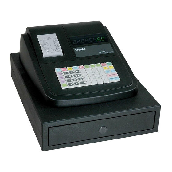
• 12(W) × 24(H) Font (Including a horizontal) Character Structure • 1.5 mm(W) ×3.0 mm(H) Character Size • 2.0 mm Column Pitch • 3.5 mm (Including 8-dot line spacing) Line Pitch • 24 (12×24 Dots/Character) Number of Column Table2-4 Character Specification SAM4S ER-180U SERIES... - Page 9 2. Product Specifications 2-2 Appearance A. Appearance Dimensions (mm) Figure2-1 Dimensions B. ECR Features ① Cover Printer ② Key Board ③ Cash Drawer ④ Cover Display ⑤ Power Jack ⑥ Front Display ⑦ Rear Display(Option) Figure2-2 Location Feature SAM4S ER-180U SERIES...
- Page 10 2. Product Specifications Memo SAM4S ER-180U SERIES...
-
Page 11: Paper Roll Installation
6. Turn the Spool Winding in 2~3 turns. (Fig 3-1 (I)) 7. Place the Spool Winding on the Paper Supply. If it loosen, turn to tighten it. (Fig 3-1 (J)) 8. Replace the printer cover.(Fig 3-1 (K)) Figure 3-1. Paper Installation and Take-Up Spool Installation SAM4S ER-180U SERIES... - Page 12 3-1-2. Program Download Description DOWNLOAD CABLE for Program Update. (Special Cable for ER-180/180T/180U) ( DOWNLOAD CABLE ) CONVERSION CABLE for Program Update. (Special Cable for ER-180U only) (CONVERSION CABLE) Separate the DC power cord and cover printer SAM4S ER-180U SERIES...
-
Page 13: Program Download
3. Installation and Operation Open the housing clam and Remove the screw. Separate the drawer cable and Remove the drawer. 3-1-3. Program Download Description Insert the download cable and Insert the DC power cord. SAM4S ER-180U SERIES... - Page 14 When download is completed, ‘100%’ will be displayed. Unplug the DC power cord. Unplug the download cable Reassemble drawer and assemble the screw as original status. Plug the DC power cord. Do the RAM ALL CLEAR and program other settings again (date and time..) SAM4S ER-180U SERIES...
-
Page 15: Operation
Use for normal registrations. Use to read register reports and perform other manager functions. Use to read register reports and reset totals to zero. Use to program the register. Use for H/W tests and special setting. Table3-1 Mode Function SAM4S ER-180U SERIES... -
Page 16: Key Board Matrix
3. While continuing to hold the “SUB TOTAL” key, plug the register into a power source. 4. The message "****** INITIAL CLEAR ******” prints when the initial clear is complete. ****** INITIAL CLEAR ****** Figure3-3. Initial Clear Key & Print Sheet SAM4S ER-180U SERIES... -
Page 17: All Clear
= = = = = = = = = = = = = = = = MEMORY 1 OK MEMORY 2 OK ER-180U EPROM INFO. VERSION : STD 01.000 CHECKSUM : C85F 2015 CLERK 00 000001 000000 Figure3-4. All Clear Key Sequence & Print Sheet SAM4S ER-180U SERIES... - Page 18 3. Press each key on the keyboard one key at the time. As you press each key. The Display shows the quantity of pushed keys. 3-2-5-(d) Test Mode key 1. Press the Mode key on key board. 2. The corresponding Mode name will be showed on the display. SAM4S ER-180U SERIES...
- Page 19 3. Installation and Operation MEMO SAM4S ER-180U SERIES...
-
Page 20: Assembly And Disassembly
10. Separate the COVER DISPLAY(()from the CASE UPPER(8). (Page 5-1) 11. Separate the HOUSING CLAM()), the COVER BATTERY(+) and two ROLLER PAPER/END(,) from the CASE UPPER(8). (Page 5-1) B. Reassembly Procedure - Reassembly procedure is in reverse order. SAM4S ER-180U SERIES... - Page 21 4. Assembly and Disassembly Memo SAM4S ER-180U SERIES...
-
Page 22: Exploded View And Parts List
5 Exploded View and Parts List [Exploded View] A.ASS’Y MAIN B. KEYBOARD C.DRAWER Figure 5-1. Total Disassembly SAM4S ER-180U SERIES... - Page 23 C/UPPER + KBD HOUSING JK44-10020A ADAPTOR:EUROPE 7.5V/2.5A JK44-10020B ADAPTOR:USA 7.5V/2.5A JK44-10020C ADAPTOR:AUSTRALIA 7.5V/2.5A JK44-10020D ADAPTOR:UK 7.5V/2.5A JK72-20376E PMO-CASE UPPER S600200032A SCREW-TAPPING:PH,M2,L8 H/PRINTER + PRINTER JK59-20003A UNIT-PRINTER JK72-20381A PMO-HOLDER PRINTER(T) JK72-20016A PMO-GUIDE WINDING:ER-5200,BLACK JK72-20015A PMO-SPOOL WINDING:ER-5200,BLACK JK95-70032D ELA-MOTOR:ER-180U,STD JK72-20763B PMO-HOLDER MOTOR:ER-180 SAM4S ER-180U SERIES...
- Page 24 5. Exploded View and Parts List B. ASS’Y KEYBOARD (LASER PRINTING TYPE) Figure 5-2 ASS’Y KEYBOARD (LASER PRINTING TYPE) SAM4S ER-180U SERIES...
- Page 25 Remark Design-Location JK59-30041B UNIT-KEYBOARD: ER-180T(STD) JK81-20085A PMO-KEY TOP 1×1 JK81-20086A PMO-KEY TOP 1×2 JK81-20094A PMO-KEY TOP SET:0~9 JK81-20084A PMO-KEYBOARD FRAME JK81-20092A REX-CONTACT RUBBER JK81-20083A ASSY-FPC,230 JK81-20091A IPR-BOTTOM PLATE JK81-20076A SCREW TAPPING(BH):M2X5 JK81-20095A BALANCE-BAR JK72-20390A PMO-BLANK KEY TOP SAM4S ER-180U SERIES...
- Page 26 5. Exploded View and Parts List B. ASS’Y KEYBOARD (LABEL TYPE) Figure 5-3 ASS’Y KEYBOARD (LABEL TYPE) SAM4S ER-180U SERIES...
- Page 27 UNIT-KEYBOARD: ER-180U(STD) JK81-20089A PMO-KEY TOP 1×1 JK81-20090A PMO-KEY TOP 1×2 JK81-20087A PMO-KEY CAP 1×1 JK81-20089A PMO-KEY CAP 1×2 JK81-20095A BALANCE-BAR JK81-20084A PMO-KEYBOARD FRAME JK81-20092A REX-CONTACT RUBBER JK81-20083A ASSY-FPC,230 JK81-20091A IPR-BOTTOM PLATE JK81-20076A SCREW TAPPING(BH):M2X5 JK72-20390A PMO-BLANK KEY TOP SAM4S ER-180U SERIES...
- Page 28 5. Exploded View and Parts List C. DRAWER (B-TYPE) – BOTTOM Figure 5-4. B-TYPE DRAWER SAM4S ER-180U SERIES...
- Page 29 C. DRAWER (B-TYPE) – BOTTOM Figure 5-5. Lubrication Points of the B-TYPE Drawer Code No. Description / Specification Q`ty Serviceable Remark S020500006A GREASE-N2 Minimum Serviceable Packing Weight : 40g S020500005A GREASE-N1 Minimum Serviceable Packing Weight : 40g SAM4S ER-180U SERIES...
- Page 30 MEA-UNIT LOCK(7V,COM) S600100013A SCREW-MACHINE: M3,L14 JK70-30043A SPRING-LOCK LEVER S600300024A SCREW-TAPTITE: M3,L5 JK95-70265B MEC-SUB LOCK JK59-50019C SOLENOID-DC: 7V JK72-20789C PMO-COVER BOTTOM JK73-11023A FOOT S600200006A SCREW-TAPPING S602100002A NUT-HEXAGON S603100002A WASHER-PLAIN JK75-50002A MEC-ROLLER JK70-30019A SPRING-PUSH S603100012A PLAIN-WASHER S600300027A SCREW-TAPTITE: M5,L10 SAM4S ER-180U SERIES...
- Page 31 5. Exploded View and Parts List C. DRAWER (G-TYPE) Figure 5-6. G-TYPE DRAWER 5-10 SAM4S ER-180U SERIES...
- Page 32 5. Exploded View and Parts List C. DRAWER (G-TYPE) Figure 5-7. Lubrication Points of the G-TYPE Drawer Code No. Description / Specification Q`ty Serviceable Remark S020500006A GREASE-N2 Minimum Serviceable Packing Weight : 40g S020500005A GREASE-N1 Minimum Serviceable Packing Weight : 40g SAM4S ER-180U SERIES 5-11...
- Page 33 Design-Location Serviceable Remark JK97-20093K MEA-UNIT LOCK(7V) JK97-20093L MEA-UNIT LOCK(7V,COM) JK59-50019C SOLENOID-DC: 7V S600100013A SCREW-MACHINE: M3,L14 S600300024A SCREW-TAPTITE: M3,L5 JK39-40301R CBF HARNESS MICRO S/W JK70-30043A SPRING-LOCK LEVER JK95-70265B MEC-SUB LOCK JK70-30019A SPRING-PUSH S603100012A PLAIN-WASHER S600300027A SCREW-TAPTITE: M5,L10 5-12 SAM4S ER-180U SERIES...
- Page 34 1SET OPTION JK75-20041A MEC-KEY LOCK: #2424 OPTION JK70-20120A IPR-DUMMY KEY OPTION JK70-20074A IPR-LEVER LOCK OPTION S604400003A RING-E: ID3 OPTION JK70-20116A IPR-LEVER PUSH OPTION JK70-40905A ICT-SHAFT LEVER PUSH OPTION JK70-30020A SPRING-LEVER PUSH OPTION S604400006A RING-E: ID5 OPTION SAM4S ER-180U SERIES 5-13...
- Page 35 5. Exploded View and Parts List MEMO 5-14 SAM4S ER-180U SERIES...
- Page 36 S1003001234 IC-MOTOR DRIVER:LB1838M,SOP,14P,225MIL, S110300004A IC-EEPROM;CAT24C512WI-GT3,SOIC8P S1106001238 IC-SERIALSRAM;23K256-I/SN,SOIC8P S1202000164 IC-VOLTAGE COMPARATOR:KA393,SOP,8P,1.27m S1203001772 IC-REGULATOR:SE1117-3.3V,SOT-223,4P S2008000001 R-CHIP:0 OHM,5%,1/10W,1608 S2008000012 R-CHIP:200 OHM,5%,1/10W,1608 R7,R8 S2008000013 R-CHIP:220 OHM,5%,1/10W,1608 S2008000016 R-CHIP:300 OHM,5%,1/10W,1608 R62,R63 R3,R11,R12,R14,R19, S2008000017 R-CHIP:330 OHM,5%,1/10W,1608 R20,R22,R23,R25 S2008000026 R-CHIP:1KOHM,1%,1/10W,1608,1% R9,R42,R43,R60 S2008000028 R-CHIP:1.5KOHM,1%,1/10W,1608,1% R4,R5 SAM4S ER-180U SERIES...
- Page 37 C-CERAMIC,CHIP:100nF,+80-20%,25V,Y5V,1608 C15,C17,C19,C20,C22, C26-C32,C35-C37 S2401000700 C-AL:2200uF,20%,10V,RADIAL,φ10*20L S2402000168 C-AL,SMD:100uF,20%,16V,F60,Ø6.3×5.7L S280100018A CRYSTAL-SMD:32.768KHz,20PPM,MC-146 S2801003388 CRYSTAL-SMD:12MHz,SX-1,16pF S3002001027 BUZZER-PIEZO:85dB,1.5V,24mA,2.048KHz,BK S3301002000 CORE-MULTILAYER CHIP BEAD:CB,SMD,1608 S3601000420 FUSE:250V,4A,SS-5,DIP,2P S3708000306 CONNECTOR-FFC:6P,1R,2.54mm,ST,BLACK S3708000327 CONNECTOR-FFC:8P,1R,2.54mm,ST,BLACK S3708001395 CONNECTOR-FPC/FFC/PIC:30P,1mm,ST,DIP,TOP CN10 S3708001418 CONNECTOR-FFC:16P,1mm,ST,DIP,TOP,IVORY, S3711004118 WAFER;BOX-HEADER,1R, 3P,1.25mm,SMD S3711004128 WAFER;BOX-HEADER,1R, 5P,1.25mm,SMD CN11 S3711003968 CONNECTOR-HEADER:BOX,3P,1R,2.5mm,STRAIGH SAM4S ER-180U SERIES...
- Page 38 S430300005A BATTERY_MS621F-FL11E,3V,5.5mAh BAT1 JK39-80071A HARNESS-POWER;ER-180U,2P,280mm,WITH CORE JK41-10953A PCB-MAIN:ER-180U,FR-4,2L,T1.6 6-2 FRONT DISPLAY PCB Part-No Description / Specification Q’TY Design Location Serviceable Remarks JK49-10012A UNIT-FND DISPLAY:ER-180,FRONT ASSY 3708-001417 CONNECTOR-FFC:16P,1mm,AN,DIP,UPSIDE,IVR, JK07-00018A DISPLAY-FND:ER180,FND*4,12PIN,Y/G U1,U2 2001-000027 R-CARBON:100OHM,5%,1/4W,AA,TP,2.4X6.0MM R1-R8 JC39-40511A CBF HARNESS:ML-80,JUMPER,AWG22,52mm,SILV JK41-10782A PCB-DISPLAY:ER-180,FRONT,FR-1,T1.6 SAM4S ER-180U SEIRES...
- Page 39 6. PCB Layout and Parts List 6-3 DUAL DISPLAY PCB Part-No Description / Specification Q’TY Design Location Serviceable Remarks JK49-10012B UNIT-FND DISPLAY:ER-180,DUAL ASSY 3708-001417 CONNECTOR-FFC:16P,1mm,AN,DIP,UPSIDE,IVR, JK07-00018A DISPLAY-FND:ER180,FND*4,12PIN,Y/G U1-U4 JK39-40804A HARNESS-JUMP WIRE:ER180,80mm,8P,DISPLAY DISPLAY HAR. 2001-000027 R-CARBON:100OHM,5%,1/4W,AA,TP,2.4X6.0MM R1-R16 JC39-40511A CBF HARNESS:ML-80,JUMPER,AWG22,52mm,SILV J1-J10 JK41-10783A PCB-DISPLAY:ER-180,DUAL,FR-1,T1.6 SAM4S ER-180U SERIES...
- Page 40 6. PCB Layout and Parts List Memo SAM4S ER-180U SEIRES...
-
Page 41: Block Diagram
7 Block Diagram 7-1 Block Diagram SAM4S ER-180U SERIES... - Page 42 7. Block Diagram Memo SAM4S ER-180U SERIES...
-
Page 43: Schematic Diagram
3) DRAWER / P_FAIL / BUZZER Part Page 8-4 4) BATTERY / EEPROM Part Page 8-5 2. FRONT DISPLAY PCB Schematics. 1) FRONT DISPLAY Part Page 8-6 3. DUAL DISPLAY PCB Schematics. 1) DUAL DISPLAY Part Page 8-7 SAM4S ER-180U SERIES... - Page 44 CON-FPC;8P,2.54MM,ST SAM4S ER-180U SERIES...
- Page 45 IF=20mA MAX 320mA (dual) MAX 40mA (dual) each LED SAM4S ER-180U SERIES...
- Page 46 1.5K 1.5K CON-BOX;3P,2.5MM,ST CON-BOX;2P,2.5MM,ST SAM4S ER-180U SERIES...
- Page 47 SAM4S ER-180U SERIES...
- Page 48 DIG4 VFD_GRD#8 VFD_SEG#8(DP) VFD_SEG#7(G) DIG3 VFD_SEG#6(F) VFD_GRD#7 VFD_SEG#5(E) VFD_SEG#4(D) DIG2 VFD_SEG#3(C) VFD_GRD#6 VFD_SEG#2(B) VFD_SEG#1(A) DIG1 VFD_GRD#5 DIG4 VFD_GRD#4 VFD_SEG#8(DP) VFD_SEG#7(G) DIG3 VFD_SEG#6(F) VFD_GRD#3 VFD_SEG#5(E) VFD_SEG#4(D) DIG2 VFD_SEG#3(C) VFD_GRD#2 VFD_SEG#2(B) VFD_SEG#1(A) DIG1 VFD_GRD#1 SAM4S ER-180U SERIES...
- Page 49 VFD_SEG#1(A) DIG1 DIG1 VFD_GRD#5 VFD_GRD#5 DIG4 DIG4 VFD_GRD#4 VFD_GRD#4 VFD_SEG#8(DP) R_VFD_SEG#8(DP) R_VFD_SEG#7(G) VFD_SEG#7(G) DIG3 DIG3 R_VFD_SEG#6(F) VFD_GRD#3 VFD_SEG#6(F) VFD_GRD#3 VFD_SEG#5(E) R_VFD_SEG#5(E) R_VFD_SEG#4(D) VFD_SEG#4(D) DIG2 DIG2 R_VFD_SEG#3(C) VFD_GRD#2 VFD_SEG#3(C) VFD_GRD#2 VFD_SEG#2(B) R_VFD_SEG#2(B) R_VFD_SEG#1(A) VFD_SEG#1(A) DIG1 VFD_GRD#1 DIG1 VFD_GRD#1 SAM4S ER-180U SERIES...
-
Page 50: Update Log
Use this page to record any special servicing information such as Service Bulletins or Supplements. When possible, record changes to Code numbers directly on the actual Parts List. Always records Service Bulletin numbers and Application Dates on this log to ensure that your data is always as current as possible. SAM4S ER-180U SERIES... - Page 51 ⓒ Shin Heung Precision. October 2015 Printed in KOREA. V1.3...
Need help?
Do you have a question about the ER-180U Series and is the answer not in the manual?
Questions and answers