Table of Contents
Advertisement
Quick Links
Advertisement
Table of Contents

Related Manuals for Insportline IN 11188


Summary of Contents for Insportline IN 11188
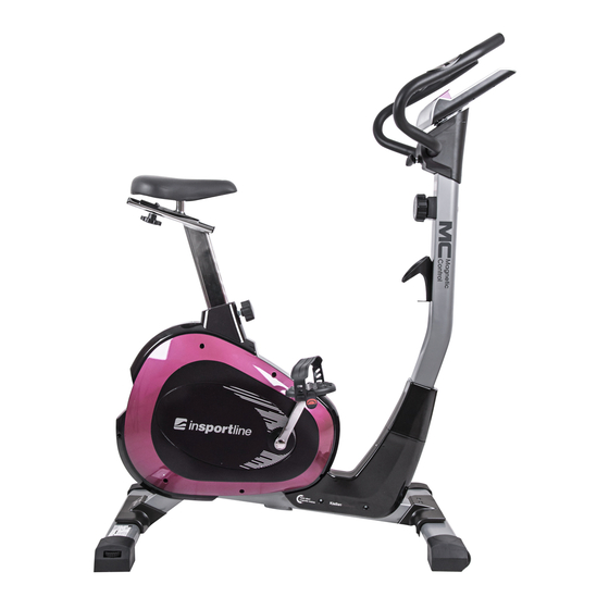
- Page 1 USER MANUAL – EN IN 11188 Magnetic Bike inSPORTline Klegan...
-
Page 2: Table Of Contents
CONTENTS IMPORTANT SAFETY NOTICE ......................3 CHECK LIST (CONTACT PACKAGE) ....................5 HARDWARE PACKING LIST ........................6 EXPLODED VIEW (ASSEMBLY) ......................7 EXPLODED VIEW (DETAIL) ........................8 PARTS LIST ............................9 ASSEMBLY INSTRUCTIONS ....................... 11 COMPUTER INSTRUCTIONS ......................15 EXERCISE INSTRUCTIONS ........................ 16 TERMS AND CONDITIONS OF WARRANTY, WARRANTY CLAIMS .......... -
Page 3: Important Safety Notice
CAUTION: Exercise of a strenuous nature, as is customarily done on this equipment, should not be undertaken without first consulting a physician. No specific health claims are made or implied as they relate to the equipment. Measurements made by the equipment are believed to be accurate, but only the measurement of your physician should be relied upon. - Page 4 18. DO NOT pull out the seat tube over the warning line “max” which showing on the tube, when you adjust the height of the seat. 19. Not for therapeutic use. 20. For your own safety, always ensure that there is at least 0.6 meter of free space in all directions around your product while you are exercising.
-
Page 5: Check List (Contact Package)
CHECK LIST (CONTACT PACKAGE) -
Page 6: Hardware Packing List
HARDWARE PACKING LIST... -
Page 7: Exploded View (Assembly)
EXPLODED VIEW (ASSEMBLY) -
Page 8: Exploded View (Detail)
EXPLODED VIEW (DETAIL) -
Page 9: Parts List
PARTS LIST DESCRIPTION MAIN FRAME REAR STABILIZER TUBE REAR STABILIZER COVER ADJUSTABLE END CAP FRONT STABILIZER TUBE FRONT STABILIZER COVER TRANSFORMER WHEEL END CAP 1set PULLEY AXLE BELT BELT IDLE WHEEL BRACKET IDLE WHEEL FLYWHEEL CHAIN COVER ( R) & (L) 1set CRANK COVER CRANK R &... - Page 10 FRONT CLAMP COVER COMPUTERE HAND PULSE HANDLEBAR ROUND END CAP FRONT COVER SCREW FOR HAND PULSE BOLT M8X55 FLAT WASHER 18/8.5X1.5 STOP NUT FLAT WASHER 20/10X2 ADJUSTABLE BOLT M6x36 SPECIAL BOLT NYLON NUT “C” RING SCREW M4X20 SCREW M4X20 SCREW M4X15 FOAM GRIPS FLAT WASHER 10/5 BOLT...
-
Page 11: Assembly Instructions
SENSOR BRACKET SCREW FRONT POST MAGNET ASSEMBLY INSTRUCTIONS GENERAL: Remove all the part of your cycle from the carton and place them to the floor carefully. Assembling your cycle is simple. Follow these instructions carefully and it should take you around 15- 20 minutes. - Page 12 STEP 2 ATTACH THE SEAT AND SEAT POST Remove the pre-assembled nylon nuts (46) and flat washers (41) from back of the seat (28). Fix the seat (28) with the top seat sliding bracket (27) and fasten with nylon nuts (46) and flat washers (41). Remove the pre-assembled M10 knob (24) and flat washer (64) from back of the seat sliding bracket (27).
- Page 13 STEP 3 ATTACH THE FRONT POST Remove the pre-assembled 4 Allen head bolts (57) and 2 curve washers (58) and 2 flat washers (41) from the main frame (1). Connect the middle section sensor wire (59) of the front post (70) with the lower section sensor wire securely.
- Page 14 STEP 4 ATTACH HANDLEBAR AND METER Put handlebar (36) with 2 hand pulse (35), foam grip (51) to the top welded shape handlebar bracket of the front post (70) and fasten rear clamp cover (31) with bushing (30) and T-knob (29). Attach front clamp cover (33) to the front post (70) and fasten rear clamp cover (31) with screws (50), screw (48) and flat washer (52).
-
Page 15: Computer Instructions
COMPUTER INSTRUCTIONS SPECIFICATIONS TIME (TMR) 00:00-99:00 ODOMETER (IF HAVE) 0.0-999.9KMorML SPEED (SPD) 0.0-99.9KM/H PULSE* (IF HAVE) 40-240BPM DISTANCE (DST) 0.00-999.9KM CALORIES (CAL) 0-9999KCAL KEY FUNCTION MODE: This key lets you to select and lock on to a particular function you want. PAUSE: Press to start or stop the operation of functions.* (IF HAVE) SET: The key allows you to choose a target value for TIME, DISTANCE, CALORIES, PULSE. -
Page 16: Exercise Instructions
it will beep for 4 seconds to indicate the completion of workout which is preset, Press any key to stop beeping. lf data is not preset, any function date will count up. 4. FUNCTIONS: TIME: The time of exercise will be displayed by pressing MODE key until brand TIME appear. SPEED: Current speed will be shown by pressing MODE key until brand SP(SPD) appear. - Page 17 Inner Thigh Stretch Sit with the soles of your feet together with your knees pointing outward. Pull your feet as close into your groin as possible. Gently push your knees towards the floor. Hold for 15 counts. Hamstring Stretch Sit with your right leg extended. Rest the sole of your left foot against your right inner thigh.
-
Page 18: Terms And Conditions Of Warranty, Warranty Claims
Side Stretch Open your arms to the side and continue lifting them until they are over your head. Reach your right arm as far upward toward the ceiling as you can for one count. Feel the stretch up your right side. Repeat this action with your left arm. - Page 19 VAT ID: CZ26847264 Phone: +420 556 300 970 E-mail: eshop@insportline.cz reklamace@insportline.cz servis@insportline.cz Web: www.insportline.cz INSPORTLINE s.r.o. Headquarters, Warranty & Service centre: Elektricna 6471, 911 01 Trencin, Slovakia CRN: 36311723 VAT ID: SK2020177082 Phone: +421(0)326 526 701 E-mail: objednavky@insportline.sk reklamacie@insportline.sk servis@insportline.sk...
- Page 20 Web: www.insportline.sk Date of Sale: Stamp and Signature of Seller:...
Need help?
Do you have a question about the IN 11188 and is the answer not in the manual?
Questions and answers